As the re:3D team wraps up and recovers from what has been an amazing South-by-Southwest experience, we wanted to provide this special update on what we did, who we met, and address some questions people had about re:3D, Gigabot and OpenGB. re:3D’s coverage at SXSW was primarily during the five days of SXSW Interactive, and came immediately after one of those “too good to pass up” speaking opportunities at the Forbes Reinventing America Summit in Chicago.
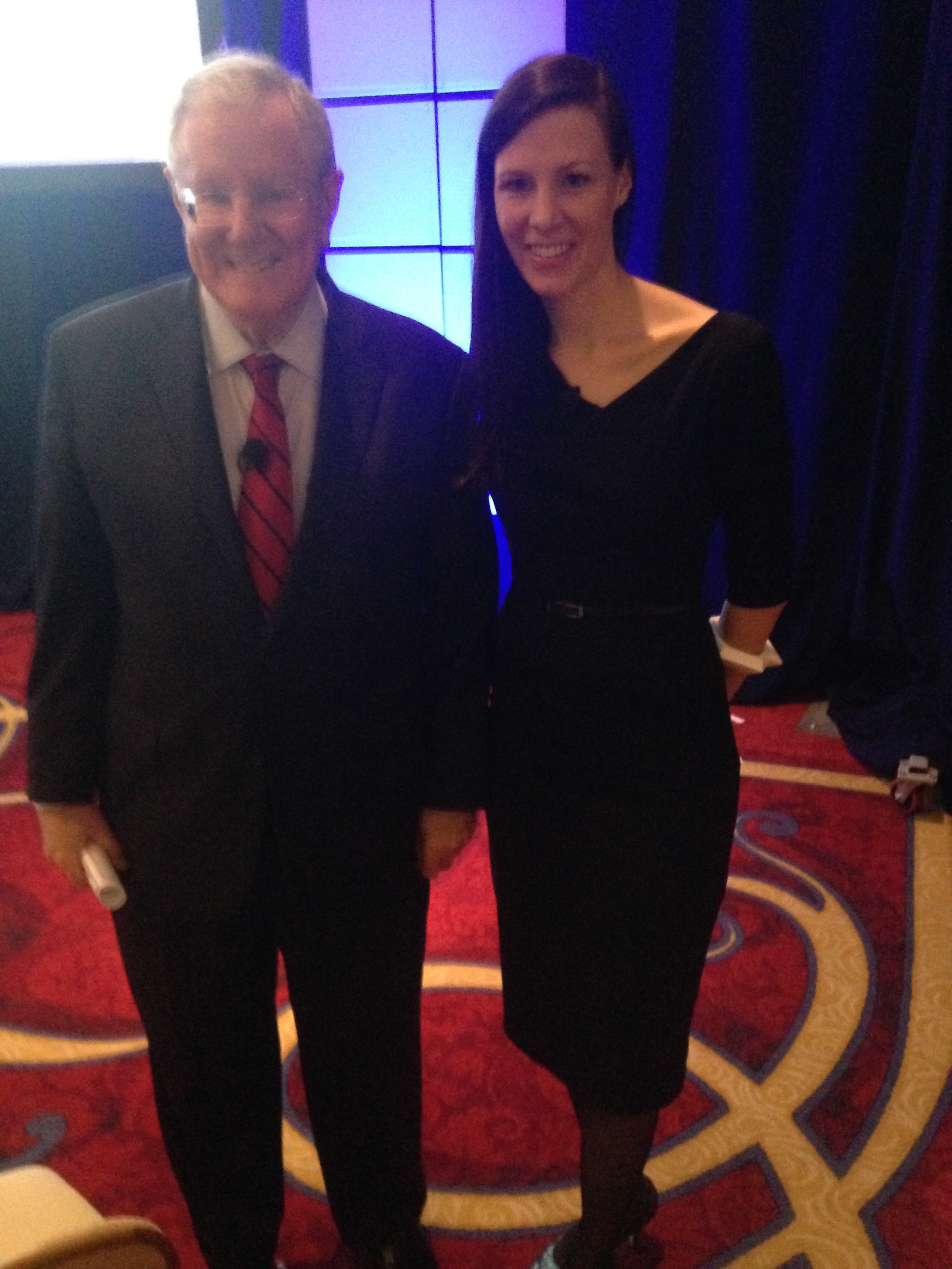
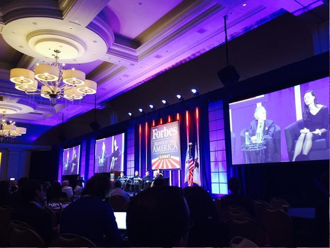
While Samantha was speaking on the Forbes panel, the rest of the team was preparing at two venues in Austin: SXSW Create, and SXSW Gaming. As a bonus we were also able to score enough of a footprint at Create to unveil our new Open Gigabot prototype, and launch our Kickstarter on the first morning of SXSW Interactive!
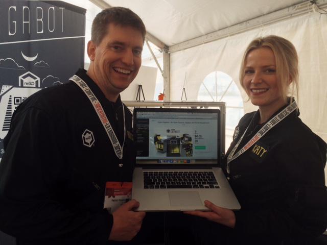
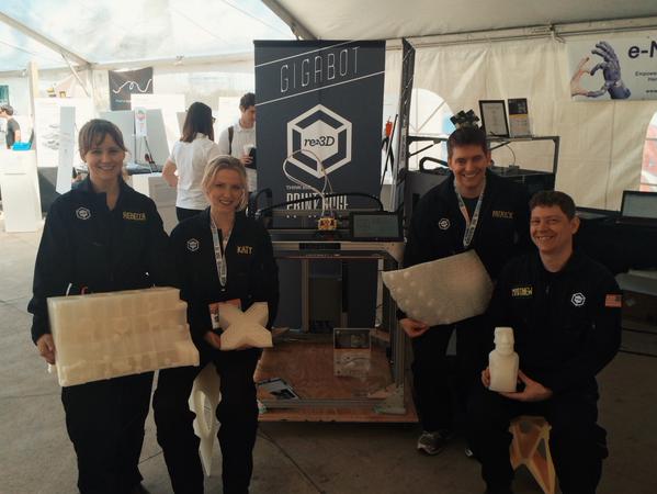
Starting with the most groundbreaking news first, after less than a week of being live, we are now halfway funded on Kickstarter for the new, experimental, Open Gigabot! The Lead Engineer for the OpenGB project, @PatrickFinucane, was on-hand to answer tons of questions, show off the touchscreen in action, and of course, lose his voice like the rest of us after 3 days of talking and sporting those swanky new re:3D flight suits. Stay tuned to the Kickstarter page, as Patrick and the OpenGB team will personally answer some questions that came up about the design process, delivery, and our unique approach to the alpha/beta testing program in the FAQ section and weekly updates.
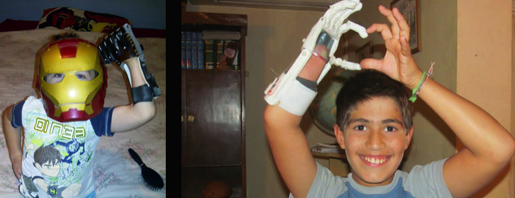
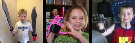
Taking a step back for a moment, you may have remembered that Gigabot was showcased at SXSW Create for the first time last year. We printed hats and swords, and mostly spread the news that we were now taking orders on our website after a successfully fulfilled Kickstarter campaign. This year was different. We were out in full force in our backyard, engaging with multiple communities in order to better understand our current and future community. In addition to the Open Gigabot Kickstarter launch, our team was invited to a very special event at SXSW Create: A Handathon, organized by the amazing folks at Hanger. Together with some other very well-accomplished 3D printing companies like Lulzbot we printed models of open sourced prosthetic hands provided by our friends at Enabling the Future to be assembled and presented to kids in need. We met some great pioneers in the prosthetic and 3D printing industries, but it was most moving to see the reaction of the attendees who might not yet have realized this great potential application of 3D printing. Open source movements have never been too shy to tackle big problems in the world, and this is no exception. We’re proud to help this movement grow and evolve with the help of the medical industry around the world.
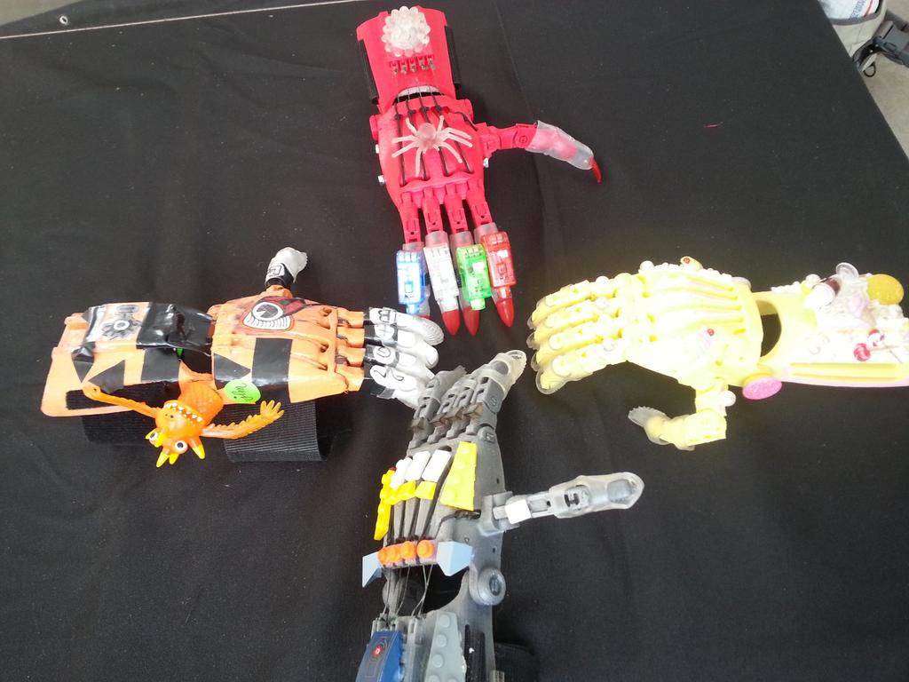
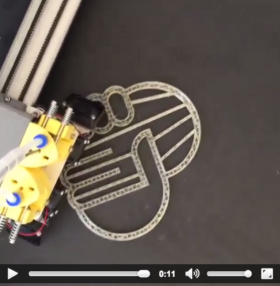
1.Prosthetic hands printed on Gigabot and decorated by the Toy Joy & Austin Rocks. 2. Instagram of Enable logo printed on Gigabot during SXSW Create
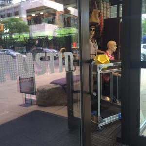
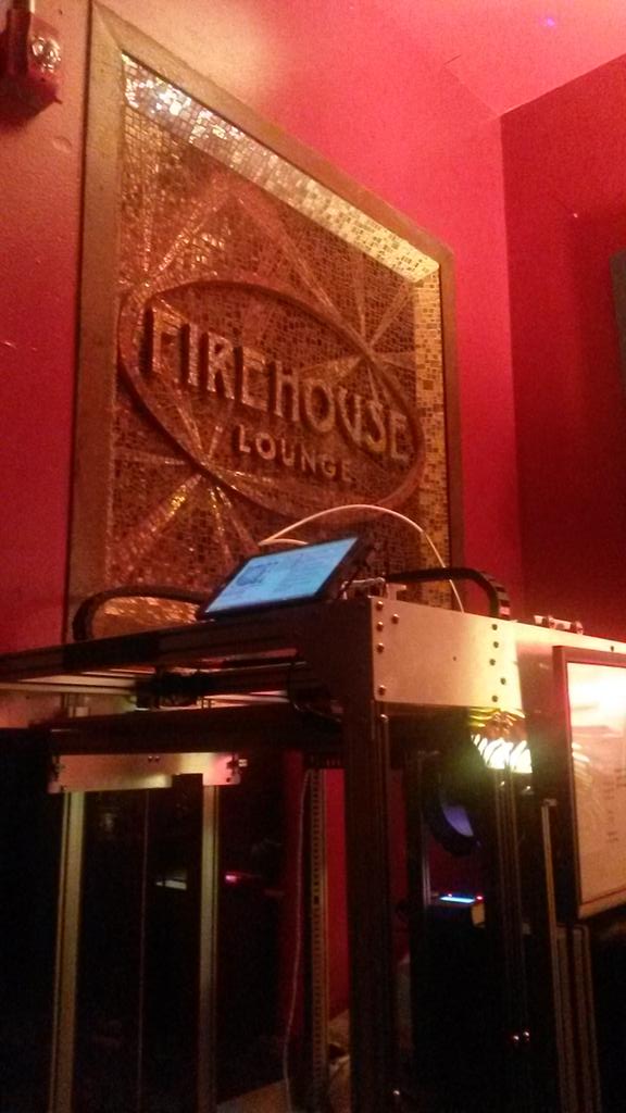
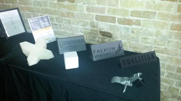
Leading up to SXSW Interactive, we also had the opportunity to print some hands with our friends at Austin Rocks and Toy Joy, who added some local flair to the prints. Gigabot loves showing off in the store front window and generating pre post SXSW buzz. With a half a dozen hands complete, Gigabot took a stroll down Sixth Street to join our Capital Factory sister company, OwnLocal, as well as the Knight Foundation for the 2nd annual News and Schmooze, a mixer for media startups, investors, and companies at Firehouse Lounge. Some great conversations around social impact were generated and we were thrilled to cross paths with our friends at 3D Hubs. The next day Gigabot had the chance to hang out at Speakeasy with our friends at Falkon Ventures, Goldman Sachs, and Collision.
Just two blocks away, the Capital Factory Gigabot was hard at work creating bottle openers live at the Google Next Wave for Entrepreneurs VIP lounge. Todd did an amazing job interacting with influencers including the Huffington Post and Rep Swalwell while Rebecca rocked a roundtable with on women in tech with Rep Morrison.

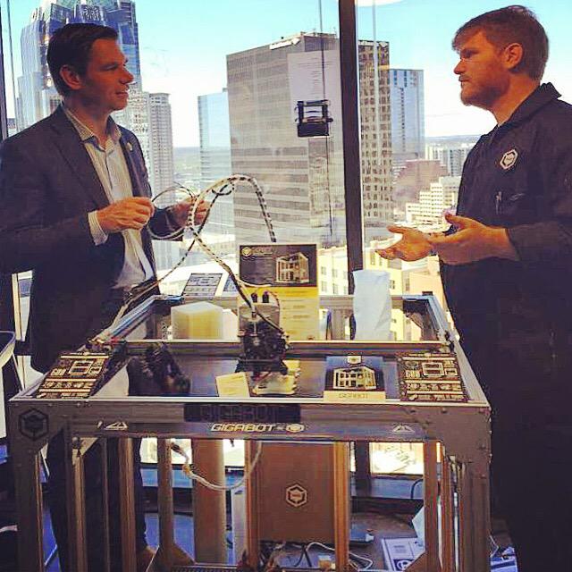
1. Printing bottle openers live with a view 2. @rpr_rebecca talks to Rep Cathy Morrison at Capital Factory 3. @re3dtodd explains 3D Printing to Rep Swalwell
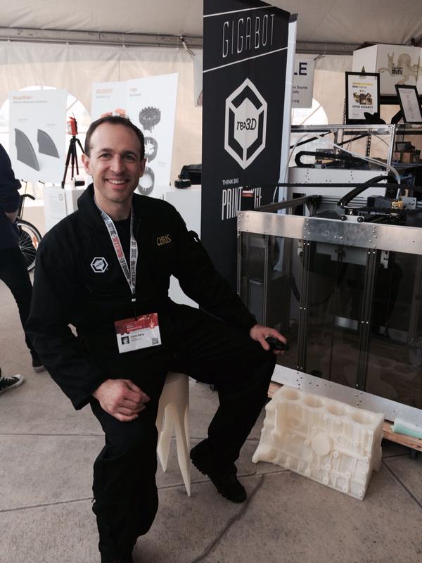
Now, let’s pick up a 12-sided die and move down the riverfront to the Palmer Events Center. Gaming at SxSW was a new community experience for us. Most of us consider ourselves familiar or even experts on certain genres of gaming, but we were blown away by the diversity of gaming experiences at the event! At SxSW Gaming, we partnered and shared a booth with Advanced Imagination, an innovative company about to release their own Kickstarter for a tabletop3D game, called Boardcraft. Our booth had a combination of a 2D version of the game, “Necro-Virus”, laser sintered models from a $100K+ machine, contrasted with models printing out live on our $9000 Gigabot – a fused deposition manufacturing (FDM) printer that could fit well in a home or local makerspace. It was really great to be exposed to the vibrant and diverse gaming community, and hopefully they enjoyed seeing the Gigabot in action with @gerty.
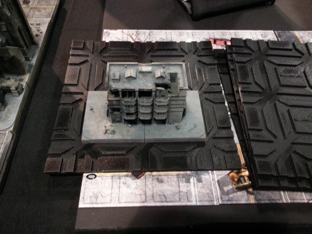
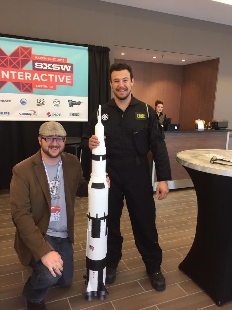
1. Boardcraft on Gigabot 2. Jim Foreman and @Ernestophocles pose with our 3D printed Saturn IV
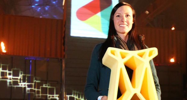
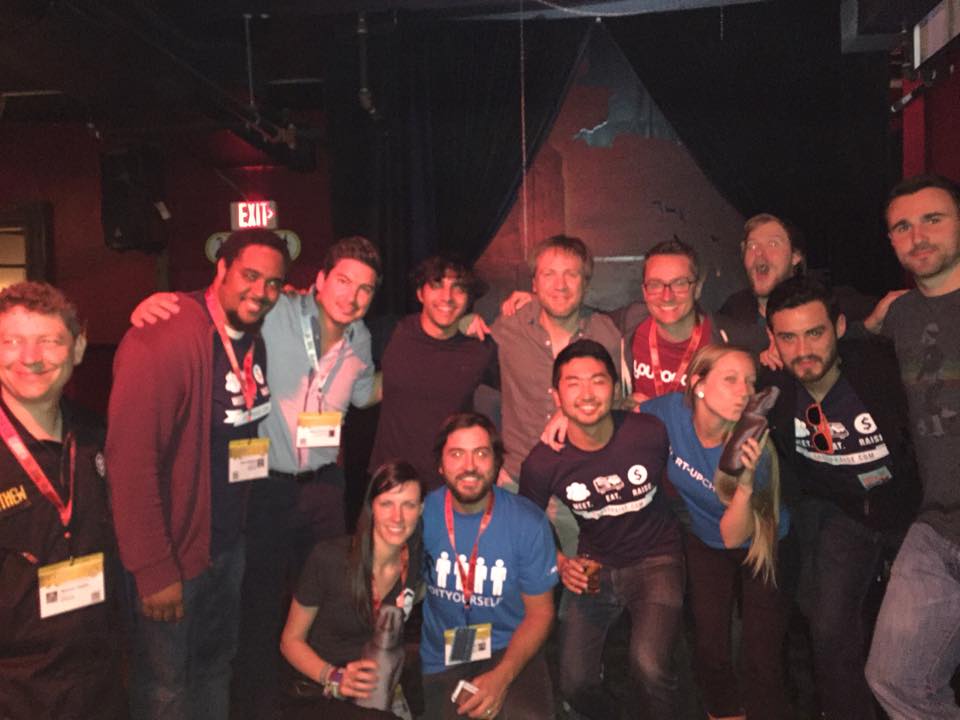
Saturday was also a big day for community engagement. In addition to engaging his fans at SXSW Create, he took time out to facilitate the SXSW 3D Printing Meetup. To hours later, @samanthasnabes shared our Start-Up Chile experience at our first panel titled “Building a Start-Up Ecosystem from Zero“. That night, we had some beers with our Chilean friends at a Start-Up Chile reunion. Along the way, Jimmy Kimmel took a selfie with some 3D printed moais from Sketchfab we gifted to our Start-Up Chile co-panelists.

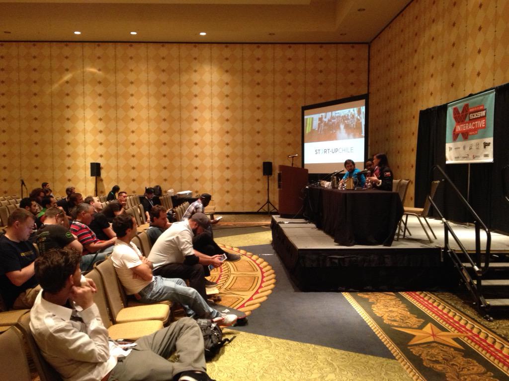
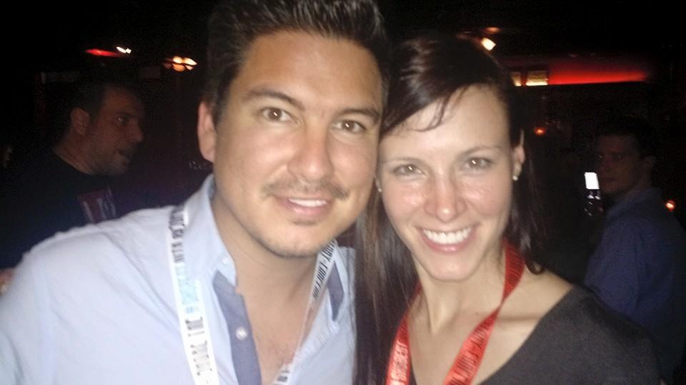
1. Jimmy Kimmel with the Gigabot Moai 2. @samanthasnabes speaking at SXSW 3. @gerty resting on our 3D printed stool 4. SUP Participant Reunion 5. Gen6 reunited with @samathasnabes & @sergiodelrio
Our last special appearances didn’t include Gigabot, but did involve some big prints. On Sunday morning we were honored to attend the IDA “Business Leaders Breakfast” with Ireland’s Prime Minister to reunite post Web Summit with Enda Kelly and take another selfie on a Gigabot printed chair.
Just a few short hours later, we were out again with a 6 ft, 3D-printed Saturn IV rocket, as well as the world’s largest 3Dprinted Snoo (aka, the Reddit Alien!). Snoo was a big hit at the Reddit/ Daily Dot event, and has consequently been kidnapped in exchange for for Karma!
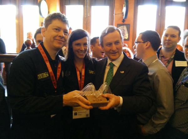
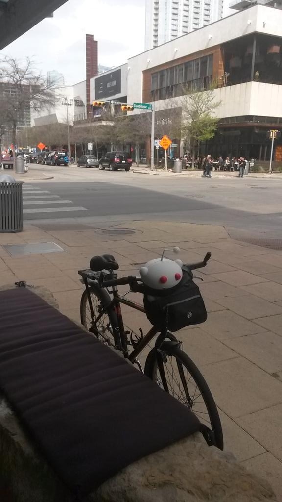
1. @chief_hacker and @samanthasnabes with Enda Kelley 2. Snoo on his way to his big debut!
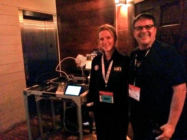
To wrap up the event, @katyjeremko attended the SXSW Innovation Awards on behalf of the OpenGB and our Innovative 3-DIY nomination. We didn’t win, but were thrilled to see Project Daniel | Not Impossible labs accept the well deserved award. The next day @larajeremko was at yet another award ceremony where she rocked a pitch at the Austin National Hardware Cup, and our friends at Curb Energy took first place.


1. @larajeremko pitching at the regional National Hardware Cup in Austin 2. @katyjeremko represents OpenGB at the SXSW Innovation Awards
Now that we have had a chance to catch a few hours sleep, we’re taking a moment to followup on the conversations we had and to capture the feedback you provided. In talking to our community, we encountered a few common questions. The most consistent questions were:
“Why are you doing another Kickstarter?”
The answer lies in our pursuit of continuous innovation. As a small hardware company, it would be easy to get bogged down in finding the best way to manufacture and support the active life of our current product, and be driven only by specific customer suggestions on how we can improve the next models. At re:3D, we have the added challenge and benefit of being a bootstrapped company (in a funding sense). This means that an R&D budget is not won in a boardroom, it is won in front of our customers. Kickstarter is the natural way to get in front of our customer as early as possible with a set of advancements, and ask if this package of features are something the community wants and needs. Judging by discussions with our customers, partners, SxSW conversations, and our current funding level after 7 days on Kickstarter, the early indication is a resounding “YES!”
Another question came up a few times was actually from Gigabot owners and people considering buying our current two-week-lead-time machine:
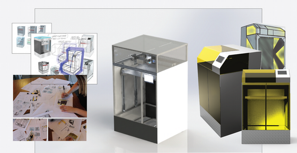
“What is the difference between Gigabot and Open Gigabot and can we expect OpenGigabot to be a regular product offering”
Currently OpenGB is an experimental Gigabot that we’re co-developing with the community. As a backer, you’re getting the first edition production model and are part of an exclusive beta-testing group. @MikeBattaglia, our Customer Service Guru and OpenGB Usability Engineer sums this up best from a customer email earlier in the week: “We are definitely not the type of company to leave existing customers in the dust!”
We listen to our entire community as we decide which features to develop and incorporate into our large format printers. Once these offerings are past beta testing and have installation instructions and video tutorials, we will consider migrating them over to our flagship Gigabot offering based what the community prioritizes. We also choose some beta testers from time to time in our community, so if you are interested, please email us at engineering@re3d.org!
This has been a longer update than anticipated when it was started, but there has been a ton going on in the past week and you need to hear it all. Between SXSW, OpenGB’s Kickstarter, numerous speaking engagements, partnership opportunities, and a constant focus on the well-being of our rockstar employees and customers, I’m personally amazed every day at what we can accomplish together, and can’t wait to see what lies around the corner!

Chris Gerty
Blog Post Author