Filament Testing – 3D Fuel Advanced PLA

Below are our notes that respect our new open source filament testing. ASTM test samples are being created and in the upcoming months you can anticipate a summary on our website that reflects our adventures in 3D printing material science. 

Material Tested: 3D FUEL/APLA

Manufacturer: 3D Fuel

Filament Diameter: – 2.85mm

Color Tested: Bright green

Date Tested: 2/29/2016

IMG_2143

OBSERVATIONS

Ease of use:  Extremely printable with excellent adhesion.

Appearance:  The green filament was vibrant with a smooth texture. Prints yielded a slightly “shiny” surface.

Size consistency:  Average, within .1mm within roll.

Color consistency: Great, consistent throughout roll.

IMG_2140

SETTINGS

Print temperature: 210 C (nozzle) / 55C (bed)

Printer Used: Gigabot

Speed: 45 mm/s

Layer Height: 0.3mm

Infill: 30%

Type(s) of print surface used: PRINTnZ

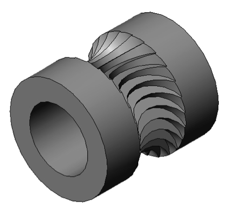
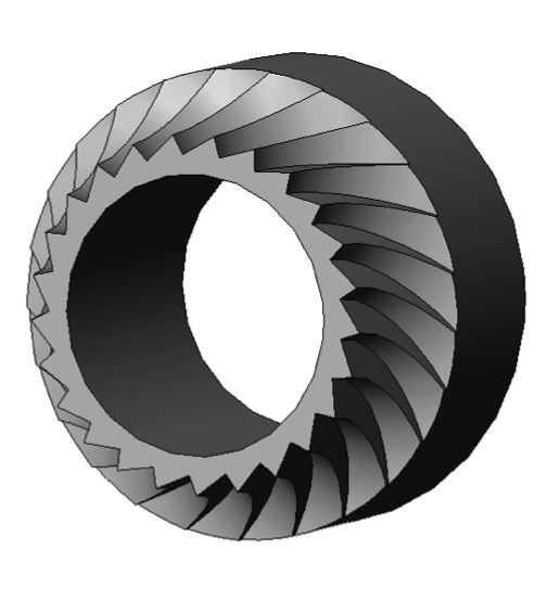
List of test files printed: re:3D’s test files 1, 2, and 3 (logo, vase, airplane gear piece)

 You can watch a video  summarizing our testing:

FINDINGS

Odor: None

Bed adhesion (1: terrible – 5: fabulous!)

  • 5 (only the settings listed above were tested, but the manufacturer’s recommendations seemed to be accurate)

Stringing (1: lots -5: none!)

  • 5 – None!

Shrinkage (1:lots-5: none!)

  • 5-None!

Interlayer adhesion (1:terrible-5:fabulous!)

  • 5- Perfect!
IMG_2154

NOTES:

  • The promise of a more heat resistant PLA is super enticing to the 3D printing community.
    • After testing, the landing gear was exposed to high temperature heat via a hair dryer and showed little warping.
      • Further controlled testing would need to be implemented to investigate this claim, but it does initially appear to be stronger and more heat resistant than traditional PLA.
  • NOTE: this filament was tested 4 months after receipt, however, for many users a 4 month shelf life is necessary.
    • Testing fresh filament is expected to yield similar or even better results.
  • Filament size consistency was about on par with most filament.
  • No delamination or curling was observed.
  • All testing was conducted at the midpoint of the temperature and speed range that the manufacture provided. It’s likely that the outcome would have been even better had the ranges had been explored in more detail.
  • The unboxing experience was well done and the recommendation sheet was highly professional.
  • We appreciated the Made in America reference, and date stamp of quality control on the box & insert.
  • Manufacturer recommended settings were easily referenced on the enclosed documentation.

RECCOMENDATIONS:

  • This filament is extremely impressive and more than exceeded it’s claims.
  • Upon review, we would highly recommend that this filament be submitted to ASTM testing by evaluating coupons at multiple temperature and infill settings.

Want to chat? Join our forum where we have initiated a thread about our experience!

https://re3d.zendesk.com/hc/en-us/community/posts/205198503-TESTING3D-FUEL-APLA

~Happy Printing!

Samantha snabes

Blog Post Author

Getting a Grip : Part 1

Getting a grip on your 3D printer filament-Part 1

With the rise in popularity of low cost 3D printers for use in homes and small business many new printer designs have recently arrived in the market. The cost of ownership for 3D printers is coming down which is driving up access in new markets. With a customer base growing outside of engineers and tinkerers it is important that 3D printers must remain near 100% reliable with near zero failed prints due to mechanical and electro-mechanical malfunctions.

One of the leading causes of print failure is the filament feeding mechanism. By surveying the literature and leveraging our current experience in hardware development we have identified a gap in the knowledgebase for understanding the mechanics and operations surrounding the extruder drive gear commonly used on FFF type 3D printers.

We have found reliability of the filament feed gear is dependent upon three factors 1) amount of contact surface are between the drive gear and the filament, 2) depth of the gear’s tooth engagement into the filament 3) number of teeth engaged in the filament at any one time and 4) the direction of the force vector imparted from the filament drive gear into the filament. R&D at re:3D delved into this problem and below is result of their work.

Figures 1 and 2 below shows a 3D rendering of the filament drive gear “Jaws” that will be mounted to the shaft of a geared NEMA 17 stepper motor.

Figure 1. Jaws filament drive gear. Figure 2. Mid-section view of Jaws filament drive gear

The Jaws filament drive gear is machined using a four axis Bridgeport CNC milling machine. In the design process our aim was to optimize the four variables stated above.

  • The amount of contact between the drive gear and the filament is maximized by machining the gear teeth using a cutting tool of the same diameter as the filament it will drive. In our case the filament is 6.0mm in diameter.
  • The depth of tooth engagement was optimized by balancing greater tooth engagement with number of teeth engaged into the filament at any one time. If the tooth engagement is too shallow there will be too little surface area and force imparted to the filament and the teeth will slip and shred the filament. If the tooth engagement is too great the risk of plastic deformation causing the filament dimension to be out of spec for the hot-end and will cause jamming of the hot-end during printing.
  • The number of teeth engaged into the filament at any one time is important in maintaining a smooth and constant push of filament into the hot-end. Consider the job of the filament drive gear is to transform the rotational motion from the stepper motor into straight line movement of filament into the hot-end. If too few gear teeth are engaged into the filament the linear motion of the filament over time will assume more of a sine wave pattern than a constant straight line movement.
  • The force vectors should be directed in the downward direction as much as possible to increase the conservation of energy in the system. Any forces imparted into the filament in the lateral direction will cause plastic deformation of the filament and not translated into pure downward force of the filament feed. It should be noted there will always be a certain amount of lateral force experienced for the pure fact that the drive teeth will need to be engaged into the filament. By studying the section view in Figure 3 below you can see the depth of engagement, the number of teeth engaged and the force vector for a 25 tooth drive gear.
Figure3 Force vectors
Figure 3. Tooth engagement, number of teeth engaged and force vectors

We are extremely excited to have optimized the design and manufacturing of this advanced filament drive gear for FFF style 3D printers. You can view a short video of the machining process on our re:Tech YouTube channel:

Stay tuned for part two in this series where we will perform data collection and force measurement in a real world application of the Jaws filament drive gear.

Matthew Fiedler

Blog Post Author