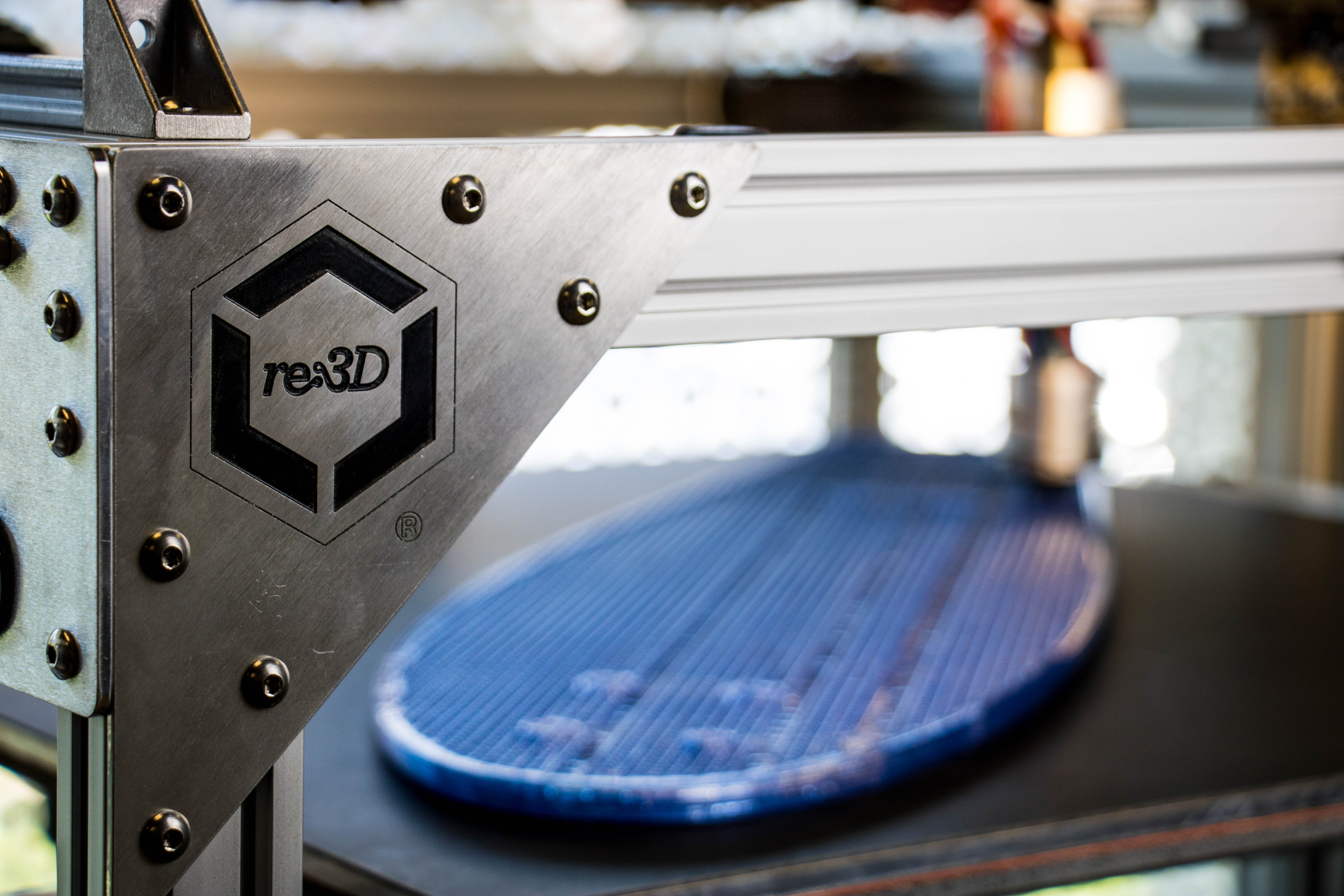
We know you’ve been dying to know what on Earth our Gigabot X pellet printer prototype was printing in the last update video, so we’re here to deliver!
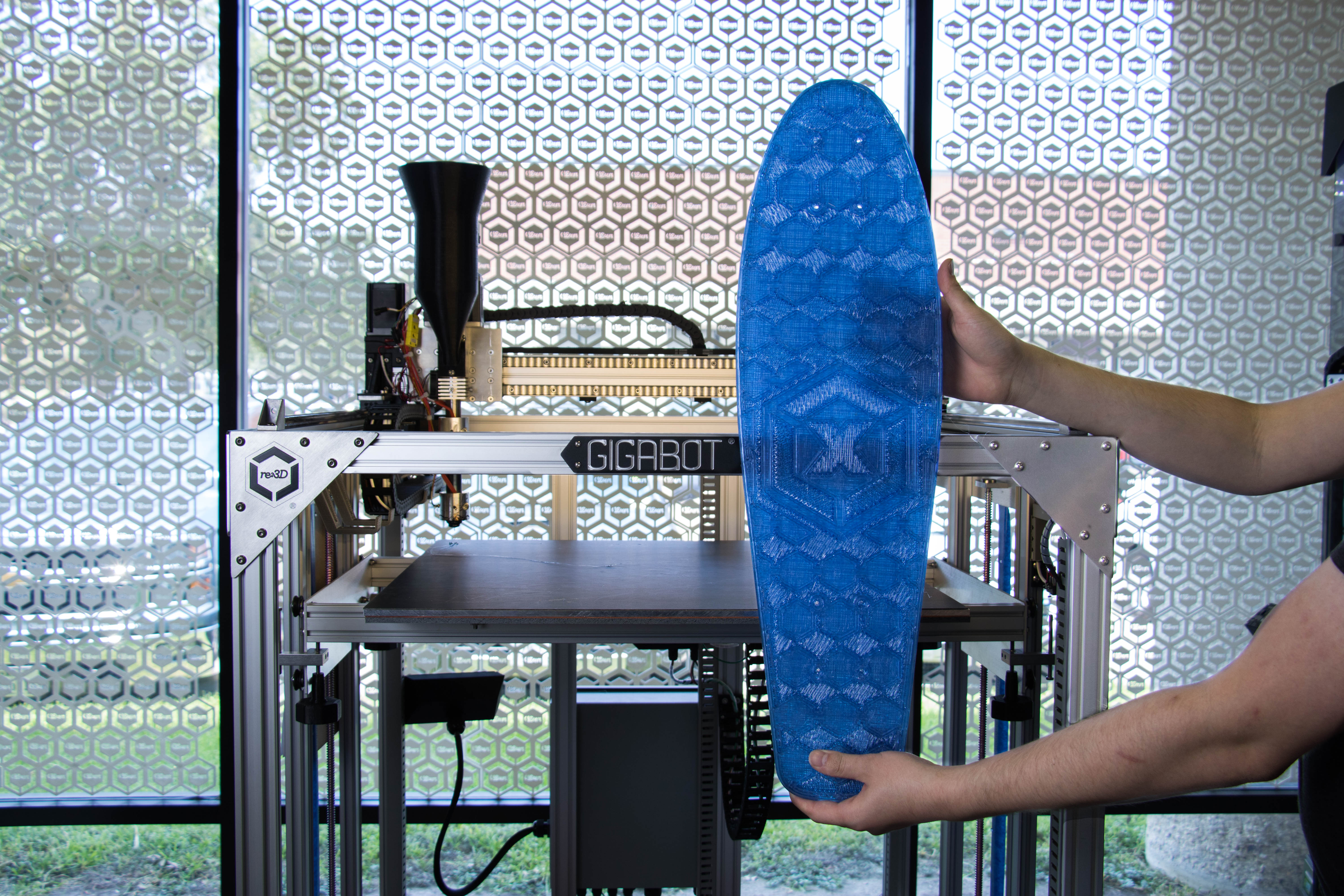
Without further ado, the reveal.
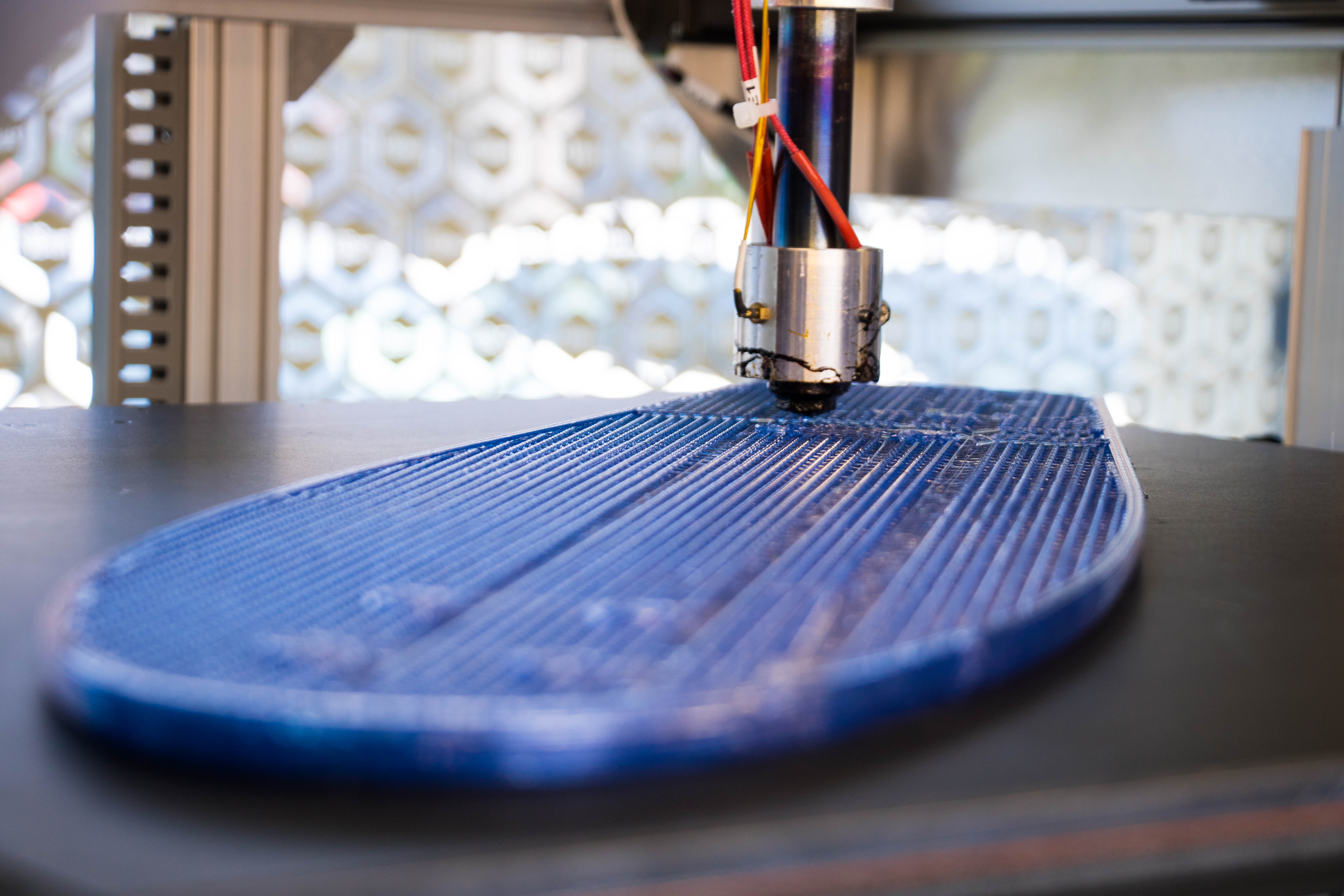
The slick design was dreamt and drawn up by one of the students working on Gigabot X material validation at Michigan Tech University. Our team was really excited about the idea of printing the board using one of our favorite new materials we’ve been testing: recycled PET.
Giving water bottles a second lease on life as a fun, functional object? As Robert put it, “You know, we had to do it.”
We went through a few trials of the board, snapping a couple of the earlier prints due to the design being a little too thin or not printing it with enough infill. We thickened up the design and increased the infill percentage to make the board a little sturdier, leaving us with a roughly six and a half hour, five pound print.
After popping on some trucks and wheels, re:3D Engineer & Resident Skater Jeric Bautista took the board for a spin behind the Houston office.
Jeric gave the board his stamp of approval. “The skateboard was really fun to use,” he said. “It was smooth to ride and the PET made it nice and springy, which is similar to normal skateboards. Seeing firsthand the functionality of recycled plastic was definitely very cool.”
Keeping plastic bottles out of landfills by giving them a new life as functional objects? That’s something we can roll with.
We’re incredibly flattered to be nominated for SXSW Innovation Award! The other nominees are amazing and we can’t wait to meet them! Check out the clip below to meet the team below and feel free to show your support by using the following social media mentions : @re_3D #openGB #InnovationAwards. Also, check back for a not-so -surprise Kickstarter campaign for OpenGB during SXSW where we will be seeking your feedback on what you want in Gigabot going forward!!
With the rise in popularity of low cost 3D printers for use in homes and small business many new printer designs have recently arrived in the market. The cost of ownership for 3D printers is coming down which is driving up access in new markets. With a customer base growing outside of engineers and tinkerers it is important that 3D printers must remain near 100% reliable with near zero failed prints due to mechanical and electro-mechanical malfunctions.
One of the leading causes of print failure is the filament feeding mechanism. By surveying the literature and leveraging our current experience in hardware development we have identified a gap in the knowledgebase for understanding the mechanics and operations surrounding the extruder drive gear commonly used on FFF type 3D printers.
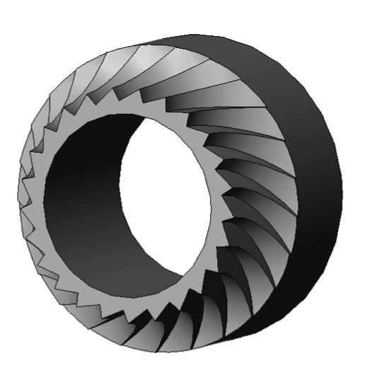
We have found reliability of the filament feed gear is dependent upon three factors 1) amount of contact surface are between the drive gear and the filament, 2) depth of the gear’s tooth engagement into the filament 3) number of teeth engaged in the filament at any one time and 4) the direction of the force vector imparted from the filament drive gear into the filament. R&D at re:3D delved into this problem and below is result of their work.
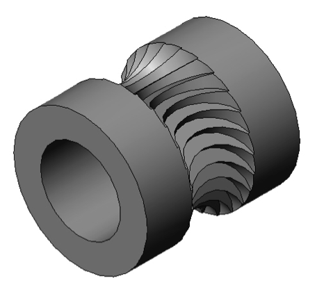
Figures 1 and 2 below shows a 3D rendering of the filament drive gear “Jaws” that will be mounted to the shaft of a geared NEMA 17 stepper motor.
The Jaws filament drive gear is machined using a four axis Bridgeport CNC milling machine. In the design process our aim was to optimize the four variables stated above.
The amount of contact between the drive gear and the filament is maximized by machining the gear teeth using a cutting tool of the same diameter as the filament it will drive. In our case the filament is 6.0mm in diameter.
The depth of tooth engagement was optimized by balancing greater tooth engagement with number of teeth engaged into the filament at any one time. If the tooth engagement is too shallow there will be too little surface area and force imparted to the filament and the teeth will slip and shred the filament. If the tooth engagement is too great the risk of plastic deformation causing the filament dimension to be out of spec for the hot-end and will cause jamming of the hot-end during printing.
The number of teeth engaged into the filament at any one time is important in maintaining a smooth and constant push of filament into the hot-end. Consider the job of the filament drive gear is to transform the rotational motion from the stepper motor into straight line movement of filament into the hot-end. If too few gear teeth are engaged into the filament the linear motion of the filament over time will assume more of a sine wave pattern than a constant straight line movement.
The force vectors should be directed in the downward direction as much as possible to increase the conservation of energy in the system. Any forces imparted into the filament in the lateral direction will cause plastic deformation of the filament and not translated into pure downward force of the filament feed. It should be noted there will always be a certain amount of lateral force experienced for the pure fact that the drive teeth will need to be engaged into the filament. By studying the section view in Figure 3 below you can see the depth of engagement, the number of teeth engaged and the force vector for a 25 tooth drive gear.
Figure 3. Tooth engagement, number of teeth engaged and force vectors
We are extremely excited to have optimized the design and manufacturing of this advanced filament drive gear for FFF style 3D printers. You can view a short video of the machining process on our re:Tech YouTube channel:
Stay tuned for part two in this series where we will perform data collection and force measurement in a real world application of the Jaws filament drive gear.
Several members of the Gigabot user community have recently inquired about dimensional accuracy in 3D printing. In this blog, I’ve attempted to explain the following concepts:
Effects of poly count on circle precision
Effects of perimeter order on circle size
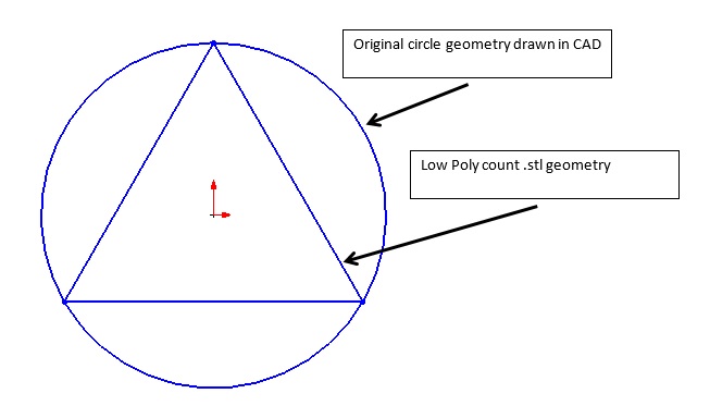
One of the challenges with 3D printing is obtaining the correct size for hole features. Currently the preferred file format for 3D printing is the .stl (Standard Tessellation Language). The STL file format describes 3D images as a series of triangles of various sizes as seen in the figure above.
The number and size of the triangles is dictated by the “Preferences” settings of your CAD program. In the extreme example where the CAD model is saved as a “Low Poly count” then the circle or hole feature would be represented by six triangles and the top view would look as the figure below. When 3D printing this circular feature the tool path would follow the triangle geometry and produce a hole much smaller than the original CAD geometry.
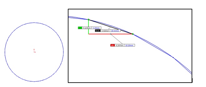
The desire to more accurately represent a true circle would lead to increase the poly count to add more triangles to the model and might look like the below image.
The above image shows a poly count 10x greater than the original “low poly count” example. Increasing the number of triangles does in fact give the 3D printer a better, more accurate circular tool path but at a cost of requiring a higher throughput of data for motion control. If the positional data being fed into the printer has too much resolution
The machine may not be capable of accurately recreating the resolution or
The printer controller may not be able to process the positional data fast enough to maintain a decent print speed.
The happy medium is achieved when the poly count is great enough to accurately describe the circle for the needs of the printed part but yet keeping the poly count low enough to allow the motion control system to print the circle at a good speed.
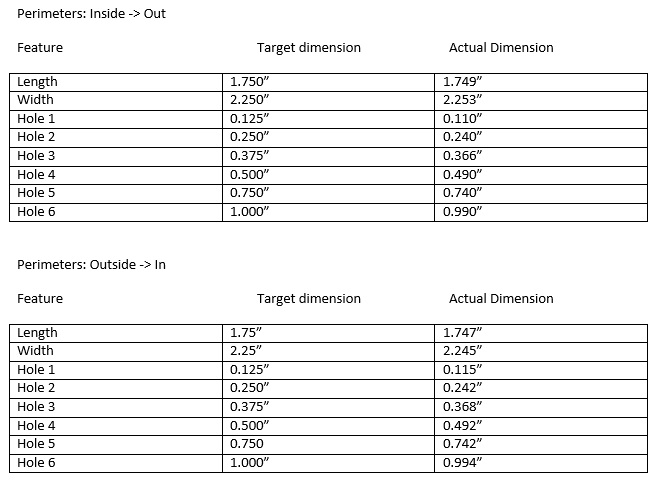
Effects of perimeter order on circle size
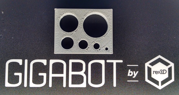
The inside diameter of holes are affected by the order of operations in 3D printing. In the below image the slicer settings have Perimeters = 2. Notice the outside of the box and the inside of the holes have two perimeters. This is often done to strengthen the part and increase the print quality. Most slicing software allow the user to decide if the print starts with the inside perimeter and moves to the outside perimeter.
When starting with the inside perimeter the part has improved surface finish. When starting with the outside perimeter the part has improved dimensional accuracy for holes.
The below image shows the actual tool path for a series of circles with diameters ranging from 1/8” to 1”. Notice that each circle is made from many small line segments.
Also note: Different Slicing programs may also influence the dimensional accuracy of part features.
Additional information on dimensional accuracy in 3D printing [Slic3r Manual]
Is this helpful? What other concepts would you like us to explore?