


The printed parts can be found HERE. Pieces must be printed using ABS except for the knobs which can be PLA or ABS, The arms should use 3 perimeters and 40% infill. The rest of the parts can have 2 perimeters and 30 percent infill.
Let’s walk through the steps to retrofit your Gigabot to use the new knob system. Note: the knobs will be installed in the 4 corners of your Gigabot. The picture shows one centered knob in the back but this is for an early revision of Open GB.
COMPLETE!!!
Happy Printing!
Mike Battaglia
Blog Post Author
@mikebattaglia

You may be thinking: “Why would a machine shop need a 3d printer?”
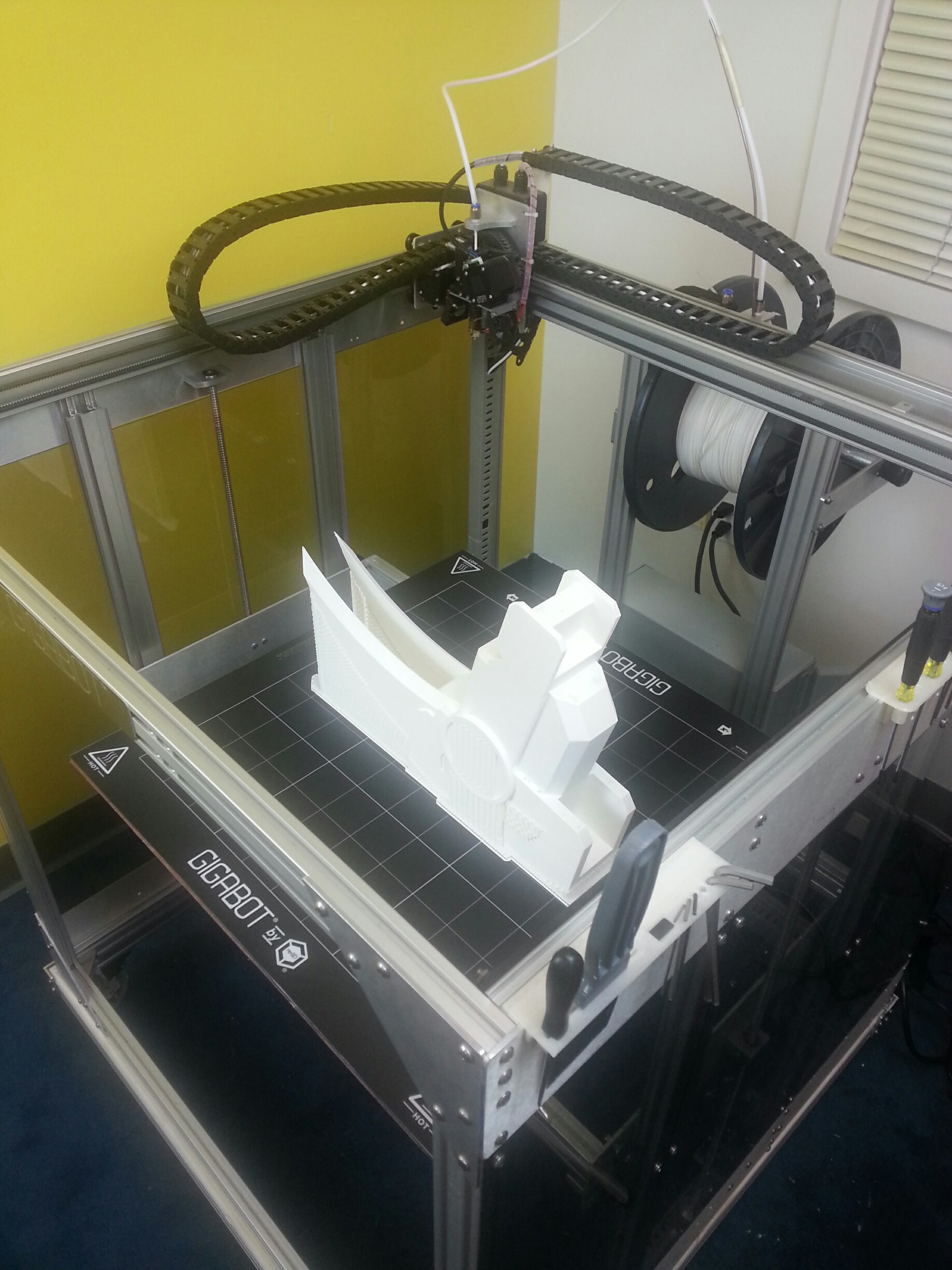
Turns out there are a lot of uses! In my case, we needed to make new fixtures to take advantage of the capabilities of our new 4th axis and the full travel of our machine. When making fixtures, cost is always a main concern, and making a bad fixture can be expensive in terms of both material and man hours.
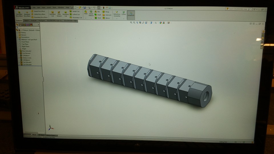
By using re:3D’s Gigabot 3D printer, we were able to design our fixture in Solidworks, export the model, and print a full size model of the fixture overnight on Gigabot (no time wasted).
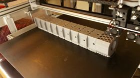
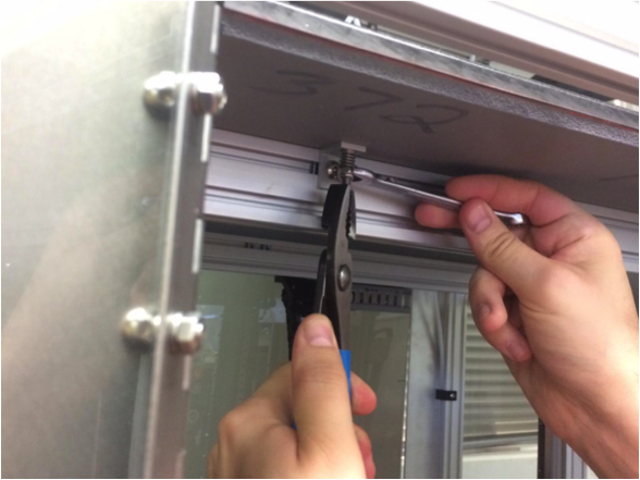
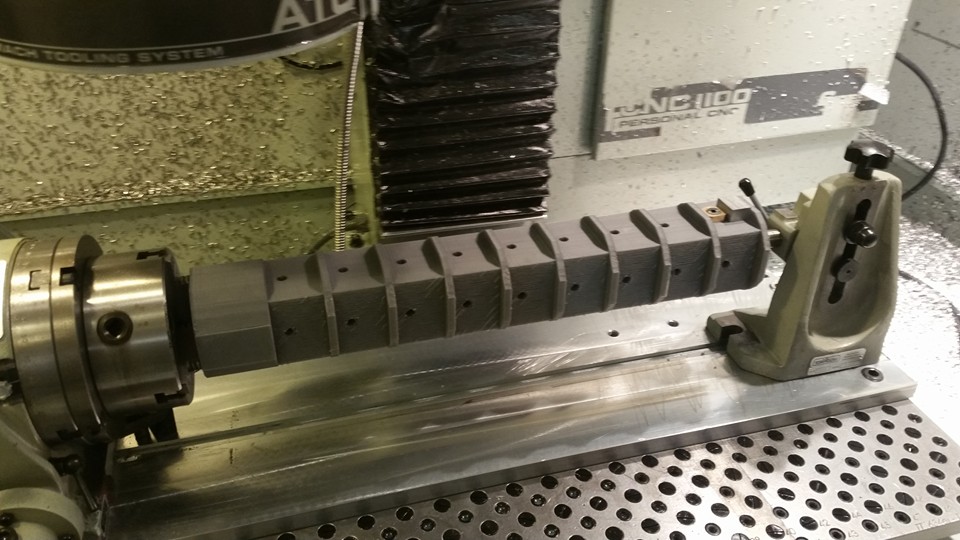
This morning, we tapped the holes for our cam clamps, put the printed fixture into the machine, and checked for clearance and travel issues. In the process we found two issues that we corrected in the solid model, and we are now printing the revised test fixture.
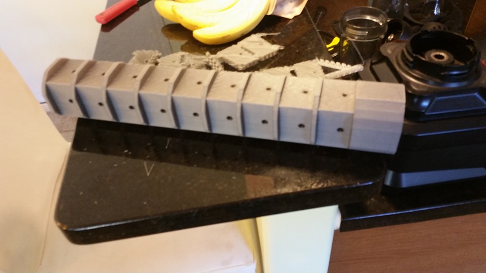
Without the benefit of Gigabot, we may have wasted a 4in diameter by 20in long piece of material, as well as hours of labor. Right now, our only cost has been a few dollars worth of plastic.
This experience has been a great opportunity for me to learn Solidworks and I’m looking forward to using Gigabot again to cut costs, create efficiencies, and to have fun in the shop!
~Happy Printing!
Steve Johnson
Blog Post Author

Manufacturer: 3D Fuel
Filament Diameter: – 2.85mm
Color Tested: Bright green
Date Tested: 2/29/2016

Ease of use: Extremely printable with excellent adhesion.
Appearance: The green filament was vibrant with a smooth texture. Prints yielded a slightly “shiny” surface.
Size consistency: Average, within .1mm within roll.
Color consistency: Great, consistent throughout roll.

Print temperature: 210 C (nozzle) / 55C (bed)
Printer Used: Gigabot
Speed: 45 mm/s
Layer Height: 0.3mm
Infill: 30%
Type(s) of print surface used: PRINTnZ
List of test files printed: re:3D’s test files 1, 2, and 3 (logo, vase, airplane gear piece)
You can watch a video summarizing our testing:
Odor: None
Bed adhesion (1: terrible – 5: fabulous!)
Stringing (1: lots -5: none!)
Shrinkage (1:lots-5: none!)
Interlayer adhesion (1:terrible-5:fabulous!)

Want to chat? Join our forum where we have initiated a thread about our experience!
https://re3d.zendesk.com/hc/en-us/community/posts/205198503-TESTING3D-FUEL-APLA
~Happy Printing!
Samantha snabes
Blog Post Author

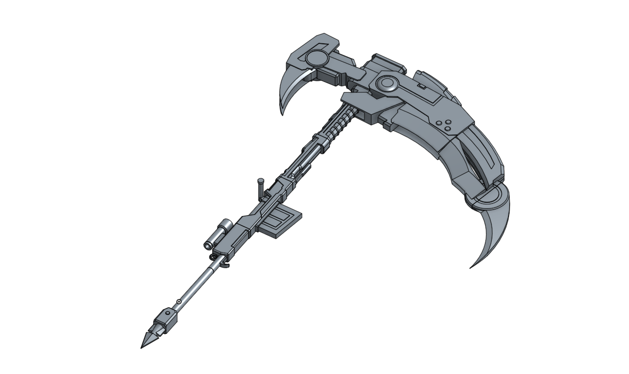
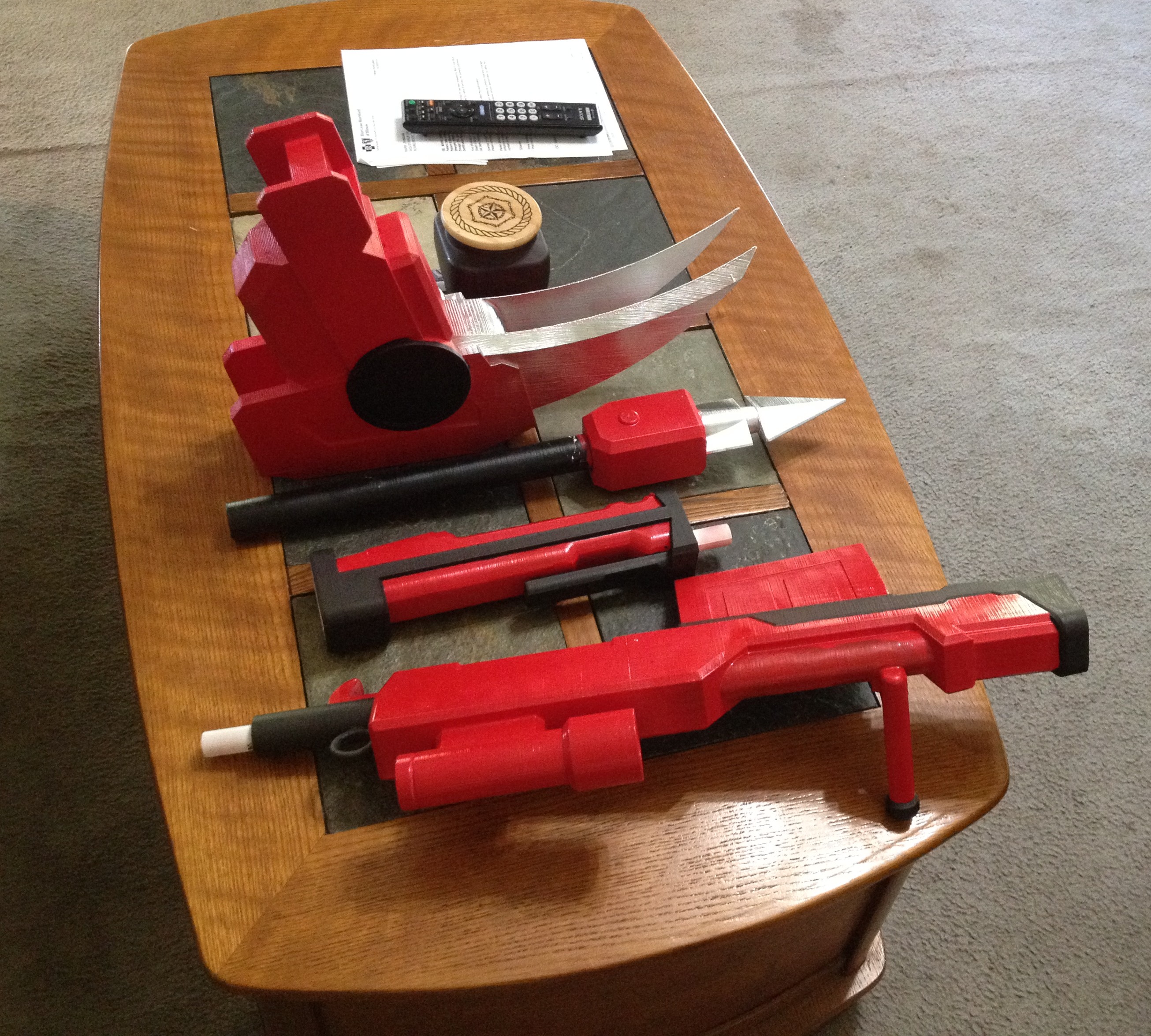
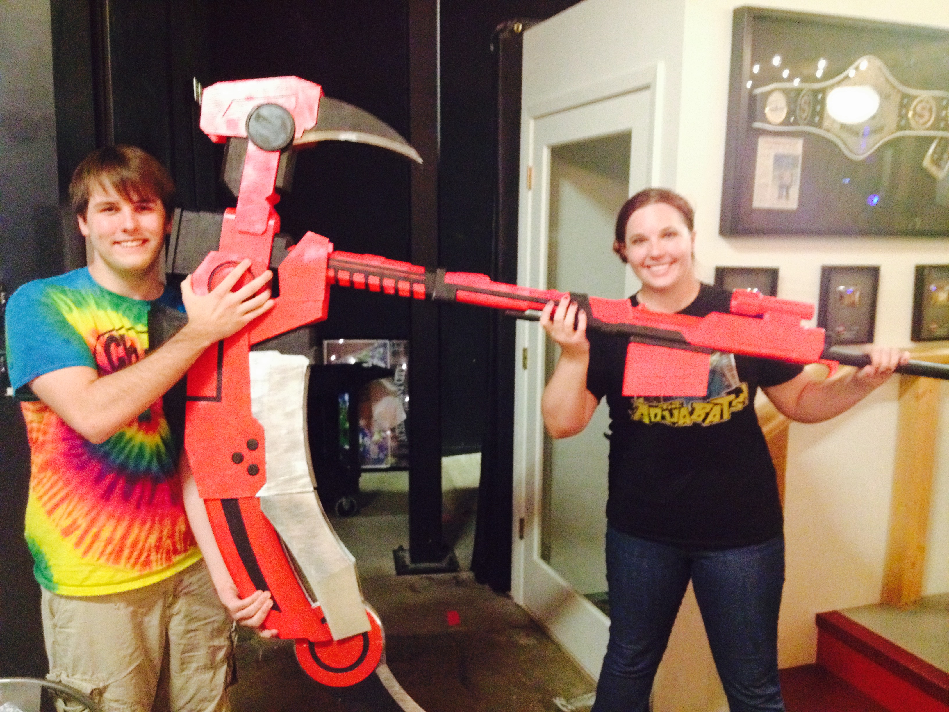
For a long time, my best friend Mason has been bugging me to watch Rooster Teeth’s animated show RWBY. Don’t get me wrong, I love anime, but I was already watching too many shows, and kept putting it off. Then, one day, re:3D’s cosplay enthusiast Rebecca asked if there was some way we could print the Crescent Rose (the instantly recognizable, 6ft tall scythe from RWBY). I immediately said yes, which made me finally binge-watch volumes 1 and 2 of RWBY on Netflix. Much to Mason’s delight, I loved it! I was super excited to make the scythe, not just because of my inner fangirl, but for the creative challenge of creating a 6 foot tall 3 foot wide scythe!
Rebecca and I debated for many hours about how to go about the design for the scythe. As you all might know, the Crescent Rose has the ability to transform into a more compact gun. We discussed the viability of this option ,and ultimately decided that because of the plastic we would be using and the laws of physics, that we should pursue making the best possible scythe-version of the Crescent Rose, and not worry about it transforming.
So, I threw myself into research. I spent many hours pausing the show and sketching, as well as staring at various other interpretations of the scythe on google images. I finally decided on a plan of action, and started modeling the scythe in Onshape, a beta CAD software.
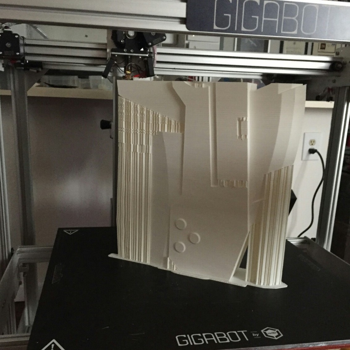
When using a 3d printer, it’s important to keep in mind how your piece is going to be printed. 3D printers start to print from a base layer up, and use supports for overhanging parts. Therefore, I modeled most of the scythe to be easily printed from a flat bottom. Although I could have modeled the piece completely true to the show, I gave up some minor design features so that my prints would be faster and use as little supports as needed. The Gigabot, because of its large print size of 8 cubic feet, allowed me to make the individual pieces much larger and easily create a life sized model of the scythe.
I made the model into 11 different pieces that could be assembled after they were pulled off the printer. I then printed these pieces using PLA on a Gigabot. I used different infills and layers for different pieces, 2-3 layers depending on how much strength I was going to need from that piece and ranged 5-20% infill depending on if I need the piece to be light or not. I usually heat the plastic at around 195-200 degrees Fahrenheit.
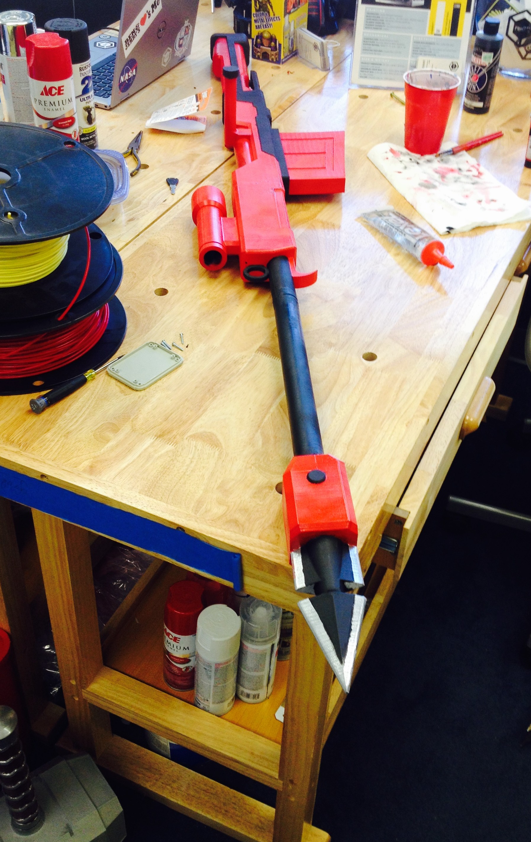
When assembling plastic pieces, together keep in mind in order in which you want to paint your piece, and the different bond strength of the glues or tapes you are using. For the Crescent Rose, I mainly used just basic Gorilla Glue super glue. For more stress intensive pieces, I used Gorilla Glue epoxy and clear caulk to give joints a more uniform look.


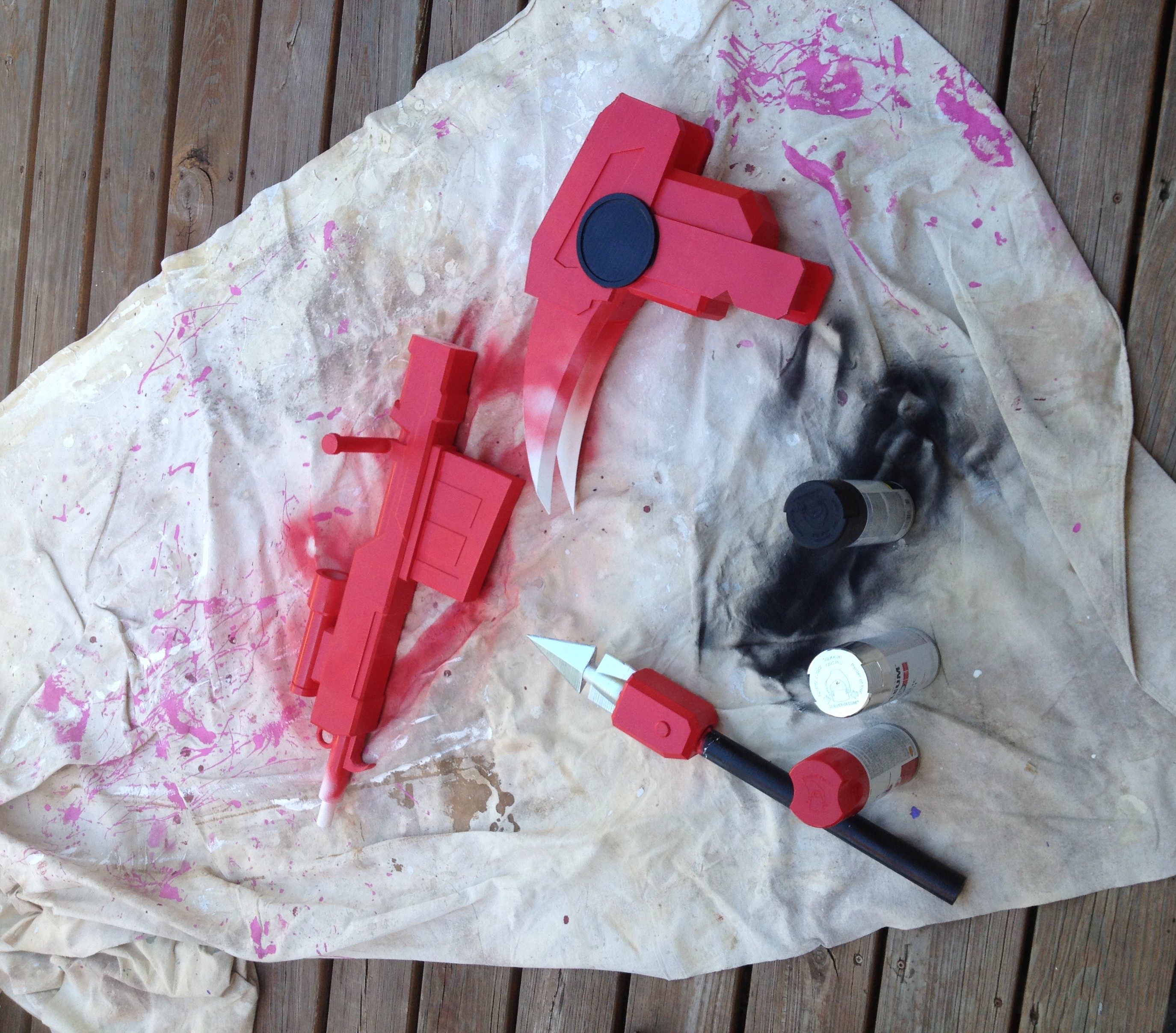
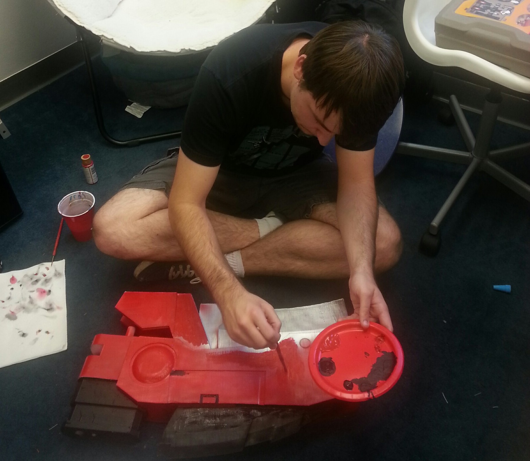
After we had finished printing all the pieces, the next step was to remove all the support material. Then, I sanded down and fixed the smaller print errors such as place where there is a slight over-extrusion on corners or small print-shifts. Finally, I started painting! A timelapse of the process is available below.
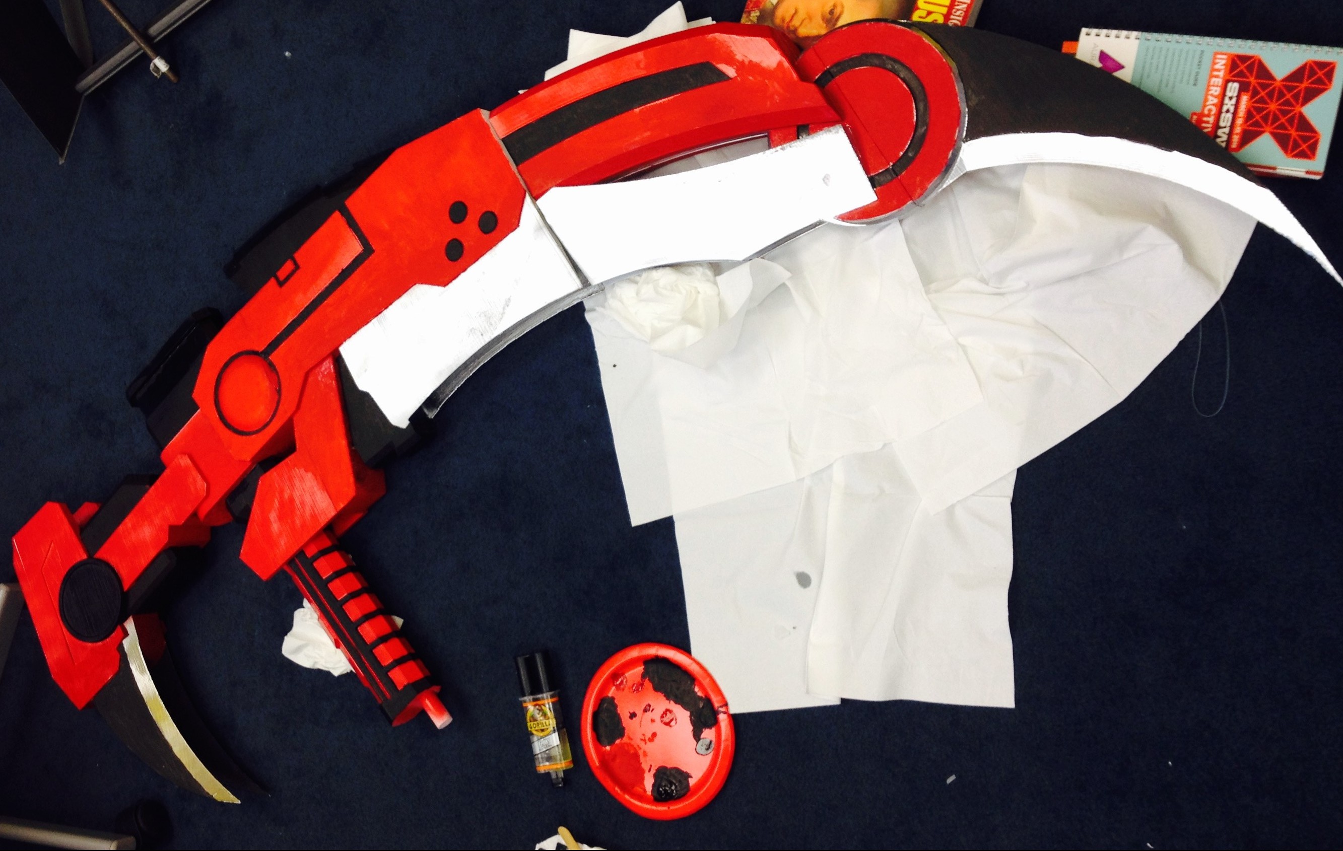
I used a basic white primer spray paint that sticks to plastic. This created a good base layer on the models that I could paint other layers of spray paints and acrylic on top of. For the majority of the scythe, I used red and chrome spray paints and then used black and red acrylics and a paint brush to finish detailing.
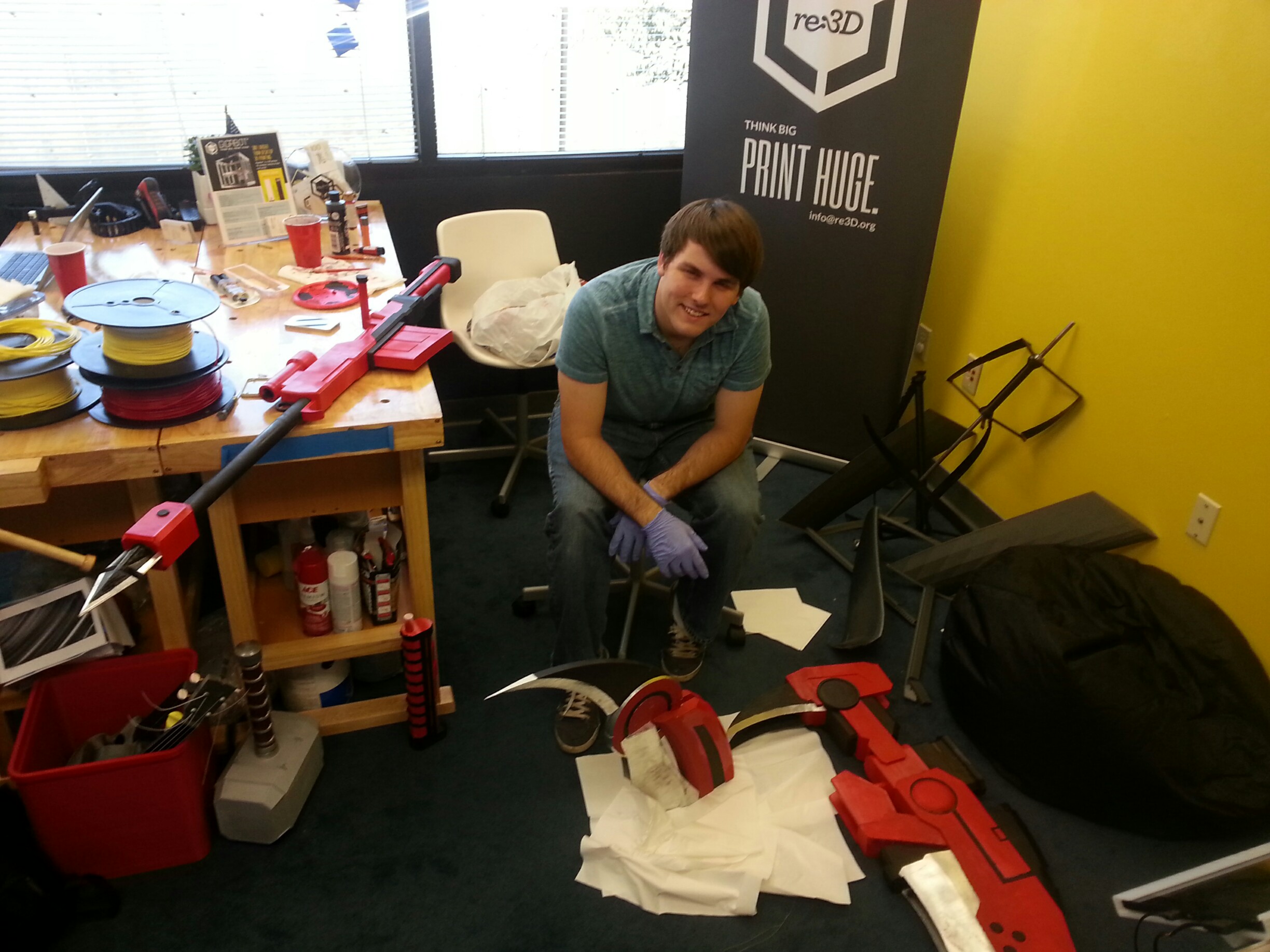
My Crescent Rose actually ended up being a little too big, finishing at 6’10” tall and 4’4” wide. I had the outstanding luck to get to bring my scythe to the Rooster Teeth offices and, who should happen to walk by but the voice of Ruby, the very character who wields the Crescent Rose– Lindsey Jones!
Everything was not all roses and sunshine though. I had some large problems throughout the course of making this scythe. Some pieces ended up being more fragile than I would have wanted, and broke a few times. The overall size and shape of the scythe creates its own unique problem. Even though the material is fairly lightweight, the scythe acts as a natural lever where the fulcrum is where the staff meets the blade, causing a large amount of pressure and tension right at the joint. My solution to this problem was more gorilla glue and wooden and metal rods drilled into the plastic and hammered through to help support the weight.
Another huge problem that occurred during the print of one of the pieces completely failed on us. The head of the Gigabot extruder got clogged 48 hours into the 55 hour print. Fortunately, when a print fails, the print usually has a flat layer at the point of failure. I was able to measure the print, and edit my model accordingly so, so I could print only what was missing. The end result looks just like a filament swap mid-print. I credit the ease of this fix to the great usability of OnShape.
Finally, the last and probably worst problem I ran into was the Texas Summer Sun… This is a problem that is unique to people in the south who use 3D printers. Even though the plastic melts at roughly 200 degrees fahrenheit, your print will warp if left in your car or your backyard too long. This happened on the largest piece of the scythe and caused my really nice print fix to be extremely noticeable. I had to reheat my piece and to try and warp it back to a usable condition– with limited success. I decided at the end that the condition of the piece after I re-warped it was good enough to merit not reprinting 55 hours worth of plastic.
In order to save you some work modeling, I posted the files on Onshape so that you can print RWBY’s Crescent Rose too!
I’m unveiling the files at RTX at the re:3D booth prior to our Panel today (Aug 8th) on 3D printing & cosplay. You can check out the panel at 1pm at the JW Marriott, Room 303.
You can find me on twitter @jacobelehmann to discuss the process in more detail.
Below are the sources I used to help me create my model.
Thanks for reading!
Jacob e lehmann
Blog Post Author

Until recently, printing large objects on FDM 3D printers was limited to small scale objects subjected only to controlled, room temperature environments. However, with the introduction of high strength materials like those offered by 3D printing filament expert taulman3D, making functional objects that can weather the Texas heat is now a possibility.
After playing a match and drinking a couple of pints of cider at Easy Tiger in Austin, Rebecca and Dave shared their musings on the paddle performance and applicability for 3D printing in table tennis.
Overall, despite my adhesion and profile hiccups, we give taulman3D’s t-glase two thumbs up! We’ve even decided to resell t-glase on our shopping site! The ping pong paddles were firm, but offered a slight give. Despite the 100 degree Farhenheight Texas heat, we weren’t worried about the paddles deforming in the rays. This new material gives table tennis players worldwide a unique opportunity to customize their paddles. We can’t wait to follow Pongtopia and see how 3D printing and this industry evolves!
Want to chat with the users? Reach them here:
Looking to chat with the t-glase wizard?
Samantha Snabes
Blog Post Author

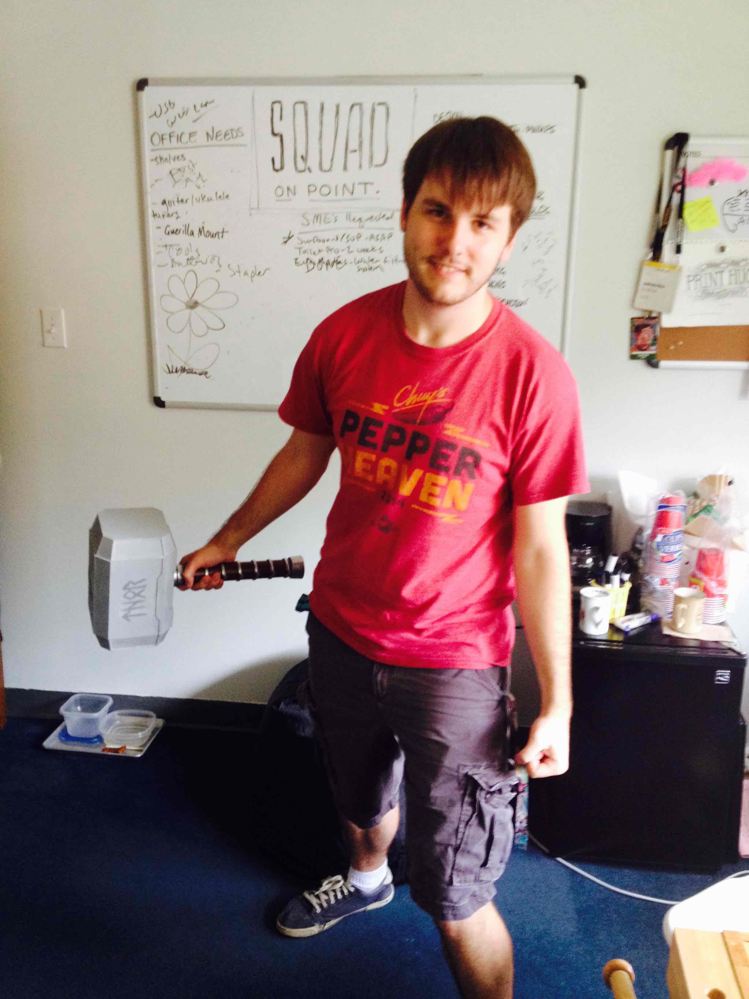
Jacob Lehmann is exploring 3D printing & cosplay during his summer internship. In his own words, he describes his design process for printing Thor’s Hammer Mjolnir
Are you tired of those pesky frost giants always ruining your day? Well fear no more! With The Thunder God’s Hammer Mjolnir, you will be able to make frost giant toast and butter them to perfection with a few extra bludgeons! Forged in the heart of a dying star or on a 3D printer (I forget which) this Hammer will always be able to tenderize your enemies with shocking ease, but only if you are worthy!
3D modeling in cosplay is great way to create large lightweight and durable props. Because 3D printing can create a shell on the outside and a mesh layer on the inside, the final product ends up being lightweight. This is great for cosplayers that want to carry around weapons that are bigger than their body all day at a convention. This also applies to full bodies of armor. 3D printing can also make higher quality props due to the ability to leverage better in precision of designs and symmetry than hand carvings or paper mache.
The Gigabot, due to its very large bed, is much better suited to printing cosplay props than a regular desktop 3D printer. Larger pieces means that there is less assembly at the end and an overall uniformity to the final model.
When I began the project I decided to make the hammer modular, meaning that it is comprised of multiple pieces that would be assembled at the end. I did this because it allows me to go back and change pieces if I want to and not have to reprint the entire hammer. This is also a good experiment for some of my later projects that will be larger than the 8 cubic feet build volume of the Gigabot. I wanted to practice with different designs as well as different methods of assembly.
My project helps to build upon and intersect with the techniques used by the artistic and inclusive cosplay community. It allows me to document the possibilities of 3D printing and provide alternative methods for creating props and wearables.
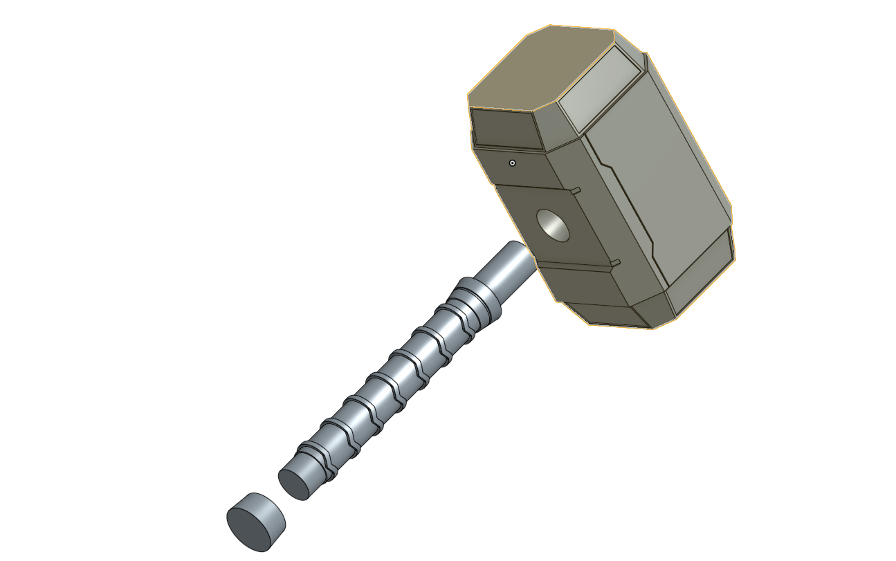
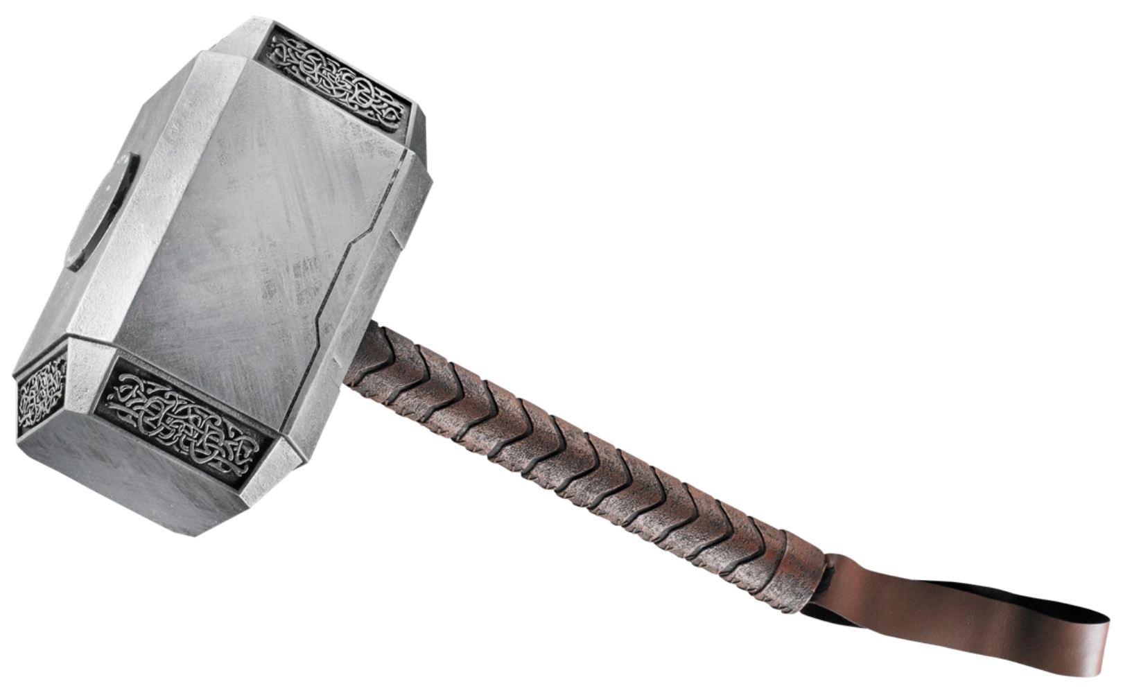
I modeled Thor’s Hammer on a Beta CAD software called Onshape. Overall it took me about 8-10 hours to complete the model with various iterations sucking up most of the time. Here are a few of the early models:
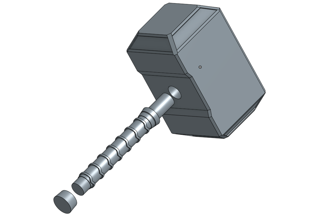
Both of these had some obvious flaws that I decided I didn’t like for the final product and I ended up sticking to the Marvel Cinematic Universe Version. The second picture shown above is one of the models where I did a lot of mirroring to save time on making the model and ended up doing a really intricate half of the model. When I mirrored the base it ended up being too long. Here is my final model:
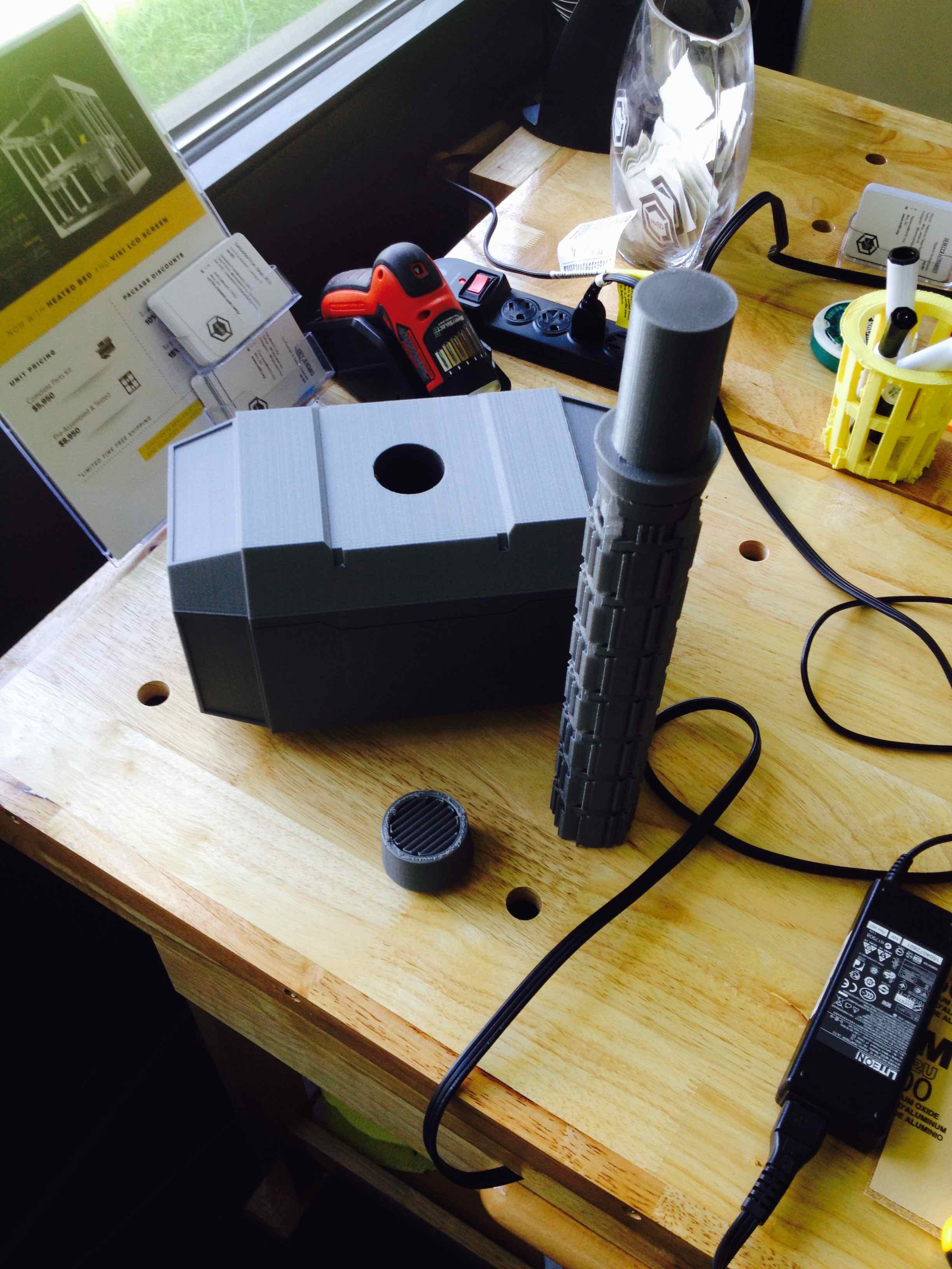
This file was then moved over to another software called Simplify3D where it was formatted for printing. All three pieces were printed on the same print on the Austin Office Gigabot and took about 18 hours to print from start to finish. I decided to print it in PLA because it is a lightweight, sturdy, and relatively cheap material. Here is what it looks like once it is printed with the supports and after I took off the support and assembled it using gorilla glue.
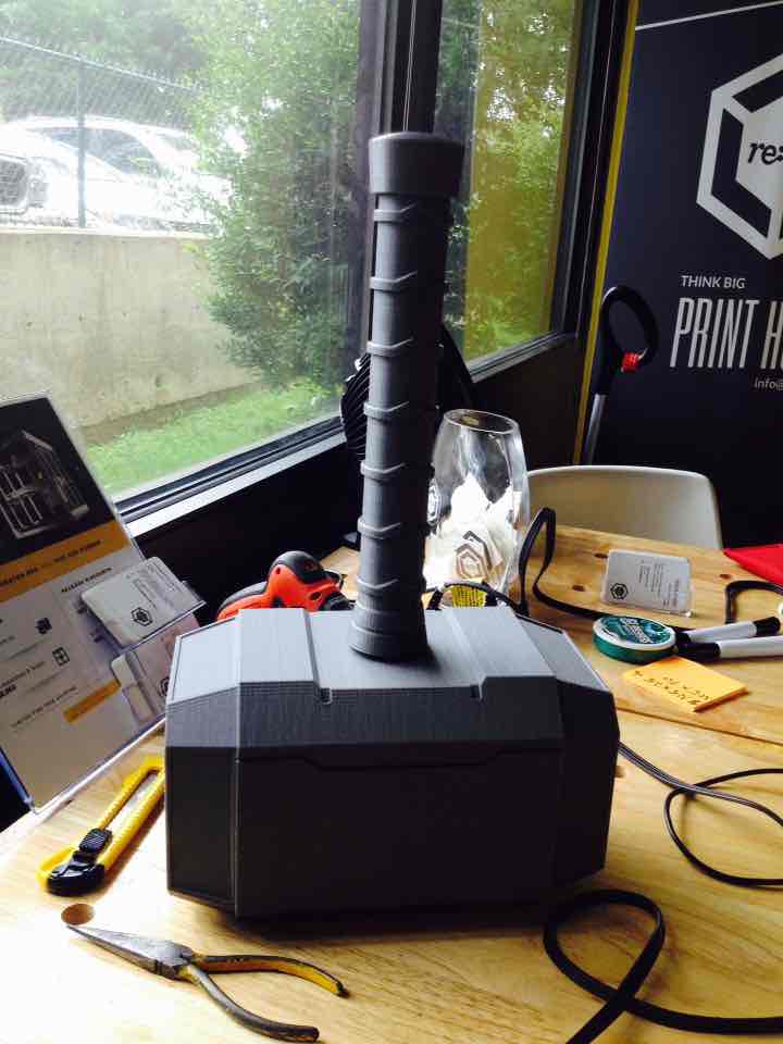
Then I began the post-processing to add color. I started by coating it with a layer of white acrylic paint but it took a long time and I wasn’t too happy with the result as it seemed kind of patchy and the acrylic did not stick to the PLA all that well.

Then I decided to use a white primer spray paint to go over and cover the rest to make it more easily painted and used a chrome spray paint to paint the handle and give the ridges a metallic sheen.

This picture is slightly out of order because I ran into a problem at the end and had to repaint the handle. After the handle was chrome painted, I painted the “leather” with a burnt umbre brown acrylic paint.

Then I finished painting the hammer with some personal touches added.
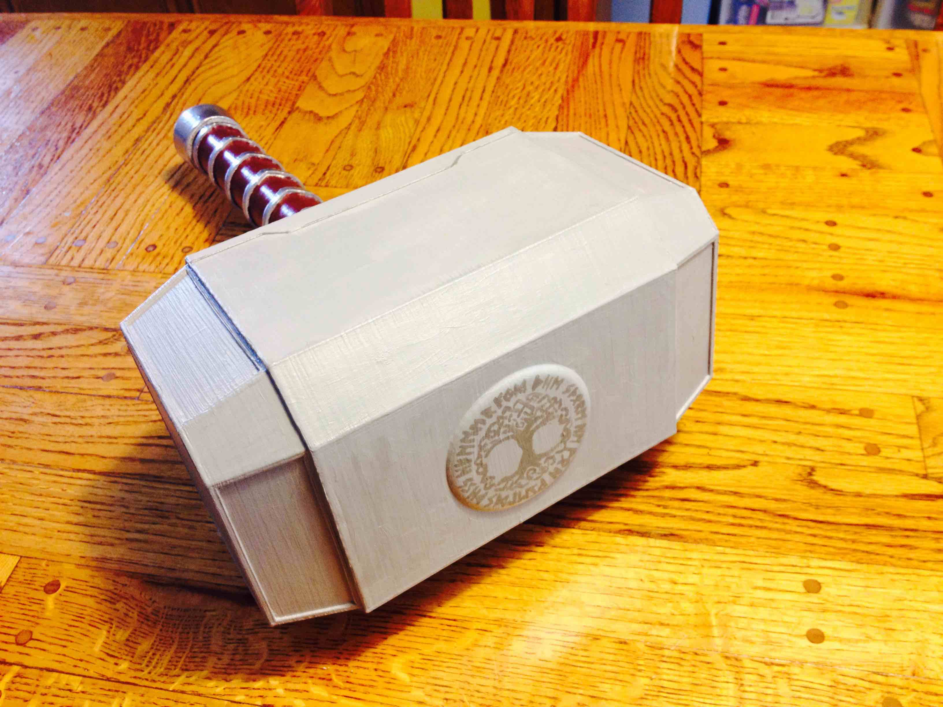
After going through the effort of glueing the pieces together, I decided it might be easier to print & post-process in one piece.

These are some of the resources I used when designing my hammer:

Jacob Lehmann
Blog Post Author
@JacobELehmann

Let’s be honest. 3D printing is hard. Not just because it builds (pun intended) upon the intersection of science & art. It’s a field that despite growing popularity, is evolving lightning fast.

For those of us at the affordable spectrum of FFF 3D printers (aka Cartesian hot glue guns), we kluge together whatever resources we have available to force a desired outcome. For me, a 3D printing newbie, this involves an impressive amount of hot glue, filament, 4 letter words, filament, sand paper, more filament, nail clippers and…..even more filament as I try, try and try again to push the limits of human-scale 3D printing.

As rather impatient non-engineer who just recently learned the difference between a Crescent and Allen Wrench, 3D printing has been quite a journey. My evenings and weekends are all too often filled with endless Internet searches in order to decipher forum lingo and to deduce how to maximize my chances of print success.
Admittedly I also have the benefit of an amazing team to give guidance and correction. Despite the advantage, I regularly make an incredible amount of mistakes as I try to be independent. I have a profound respect for those more fluent in large-scale 3D printing that model success after success online. However, I’m finding I learn more from the fracasos I inspire at least a couple times a week while currently supervising three Gigabots running 24/7.

So, in the sprit of transparency, and urging of my Coaching Fellowship Mentor Monica Phillips, I’ve begun to document my failures. My hope is that perhaps that these confessions help another amateur or, at least give my teammates & other lovers of additive manufacturing some comic relief.
Here’s the first of the series. If you’ll excuse the vertical video and amateur filming, we’ll do our best to post one a week to our What Not To Do YouTube Playlist, and perhaps coerce some other members of our team & community to share their laughs, tears, and lessons learned as we work together to take 3D printing to new dimensions.
~ High Five
Samantha Snabes
Blog Post Author
samantha@re3d.org
@samanthasnabes

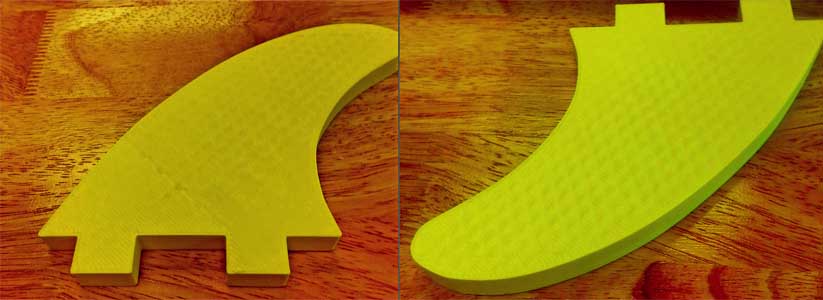
Akshay Prakash is designing and 3D printing a full-sized, functional surfboard for his summer internship. In his own words, he describes his design process:
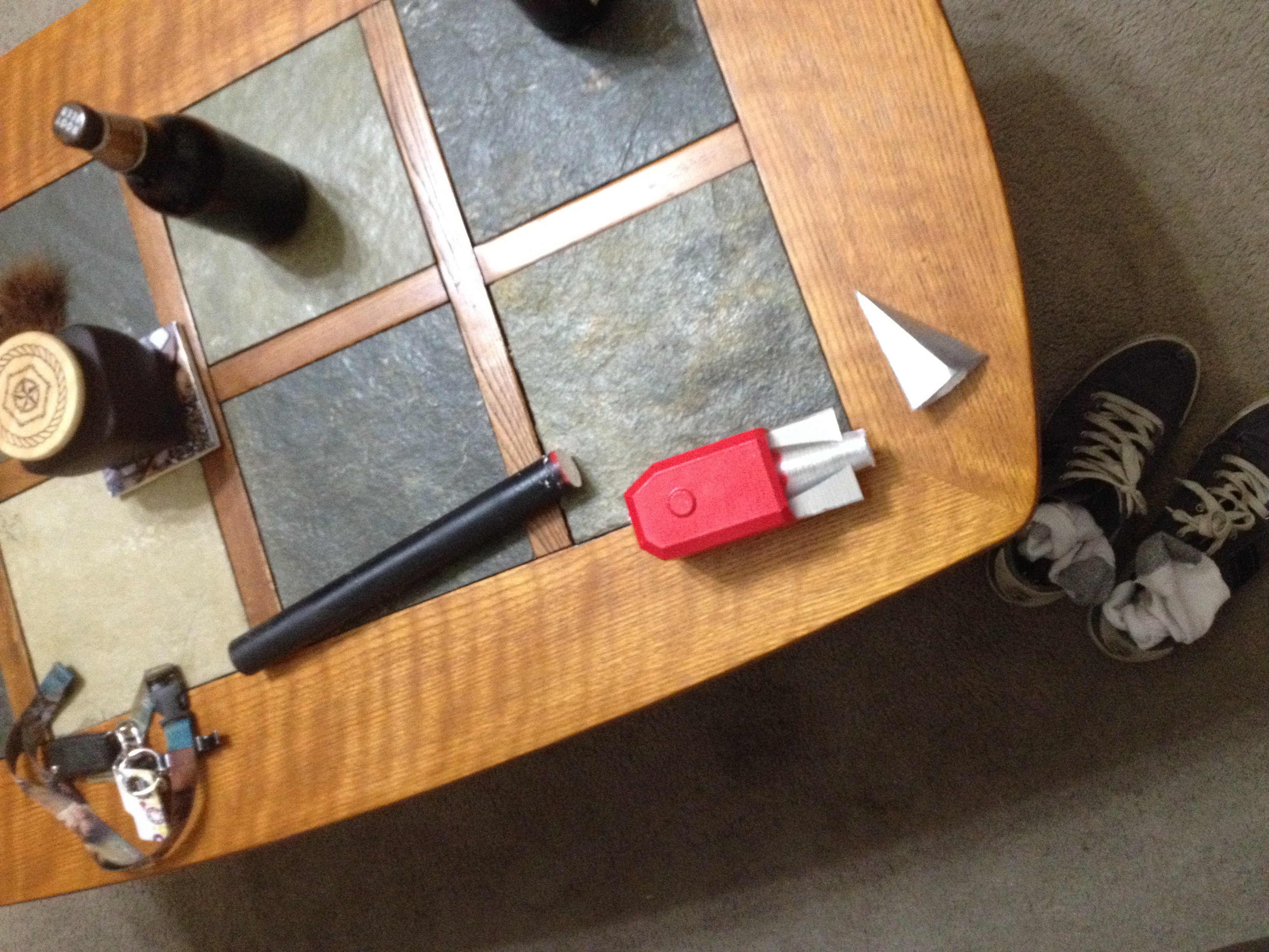
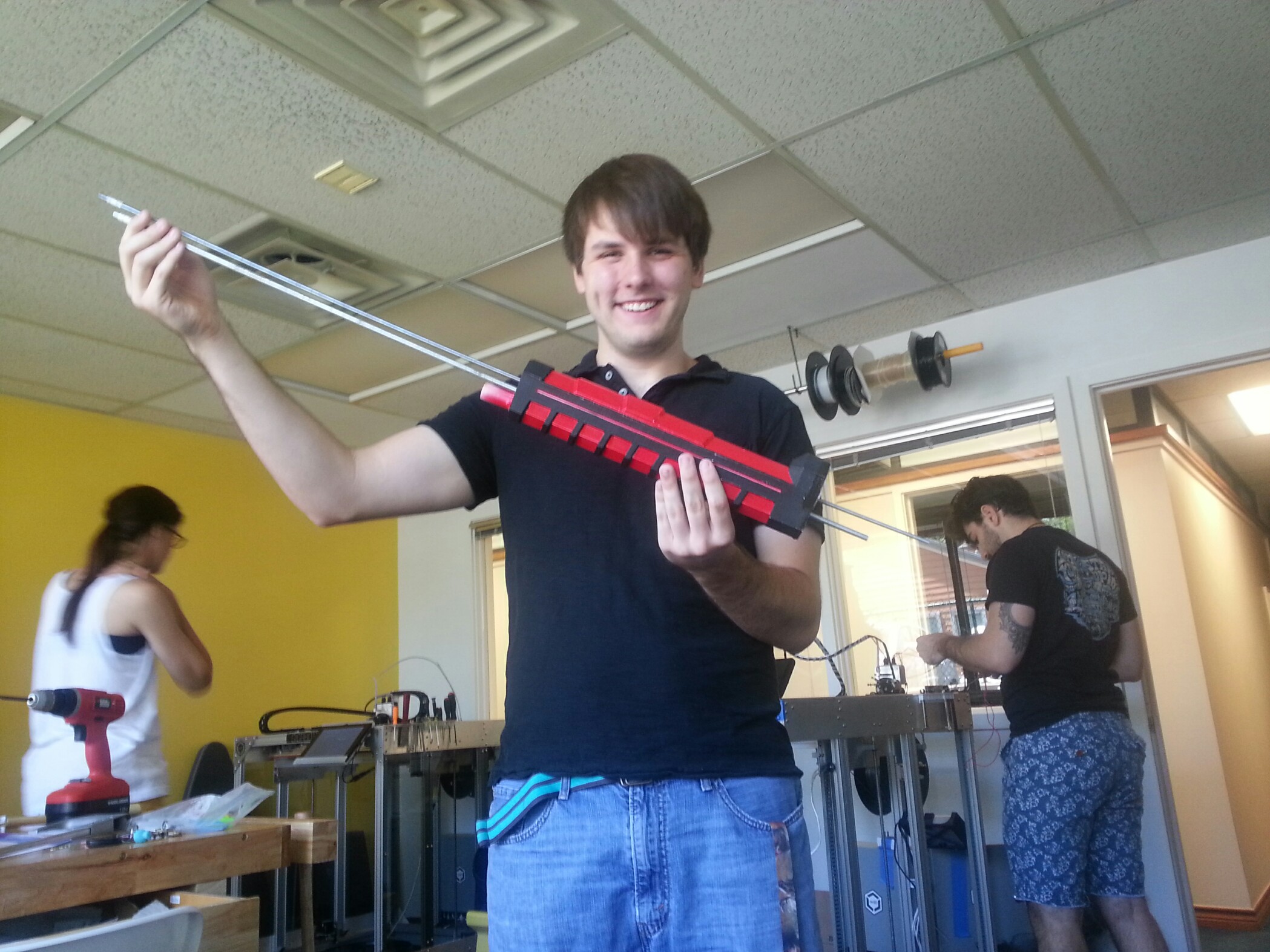
I just wanted to write this post to let you all know that the 3D printed surfboard project is going smoothly. I have finished the CAD modeling of the final product (video below) and hopefully will be printing the full scale model later in July. But for now, I am very excited to say that I have successfully finished the printing of an important part of the surfboard, the fin or skeg. The main function of the fin is to provide lateral resistance against the water such that, when turning, the tail end of the board does not slip out from underneath the surfer. In addition it allows the surfer to travel more easily in the direction in which he/she wants to move in.
Anyways, one of the concerns that I had coming into this project was the waterproof or tightness of 3D printed models, as well as their relative buoyancy when compared to the standard design of surfboards which is fiberglass encasing a foam core. What I was delighted to find out, after some tests with the fin that I had printed, was that 3D printed models with a 20% honeycomb infill with two solid layers on either side not only exhibits a similar mass to volume ratio as that of the fiberglass boards, but also is watertight without any post-production modifications.
Moreover, this, I hope, will have somewhat of an impact on the surfing industry. The current methods being used, i.e. the fiberglass and foam surfboards, often result in a large amount of harmful waste that is detrimental to the environment, whereas with 3D printing there is minimal waste, as you are only making the parts that you need, and in addition any excess can be burned off cleanly thanks to the properties of PLA. Furthermore, 3D printing paves the way for new levels of customization and experimentation allowing anyone with access to a 3D printer to design and implement their own fin, strap mount, or any other part they desire to alter based on their own wants and experiences.
Please share any suggestions for improvement!
akshay prakash
Blog Post Author
@akshay_1prakash
re:3D’s Headquarters is Moving to Austin! Delivery will be delayed until June 2024 for orders placed after May 1, 2024. LEARN MORE