Engineering Updates – Thermocouples, Hot Ends, and 3D Printing Research

This is called the “Engineering” Update, but it’s really a reflection of all the work going on at re:3D – engineering, R&D, customer service, operations and everyone else included. As our company ethos begins, “We are a team…”, and that team has been working hard to solve problems for our customers, improve the performance of our products and contribute to the body of knowledge within our additive manufacturing industry. Here are a few snapshots of what’s been happening at re:3D since our last post.

The Gigabot FFF (Filament) Platform

MCU Thermocouple Errors

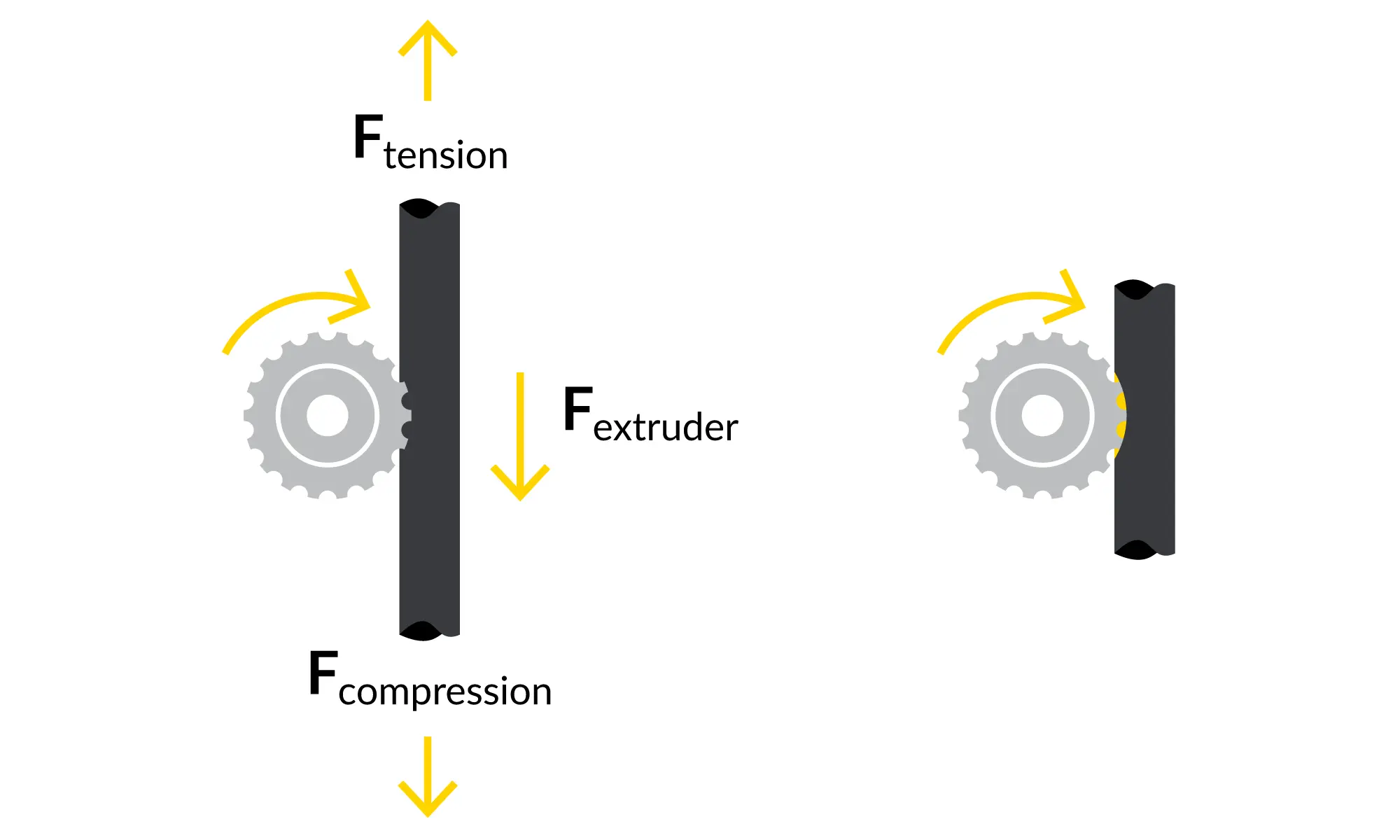
For the past couple of years, an intermittent problem would pop up on the Gigabot 4 (and GigabotX 2) printers related to the thermocouples. Sometimes the printer would throw an “MCU shutdown: Thermocouple reader error” fault during the bootup cycle (Figure 1). There were some arcane incantations that could be performed to sometimes clear the fault in any given instance, but ultimately, better grounding of the extruder seemed to solve the problem. Recently the error started showing up again, potentially delaying product shipments. So the engineering team put intense focus on investigating the cause of the error.
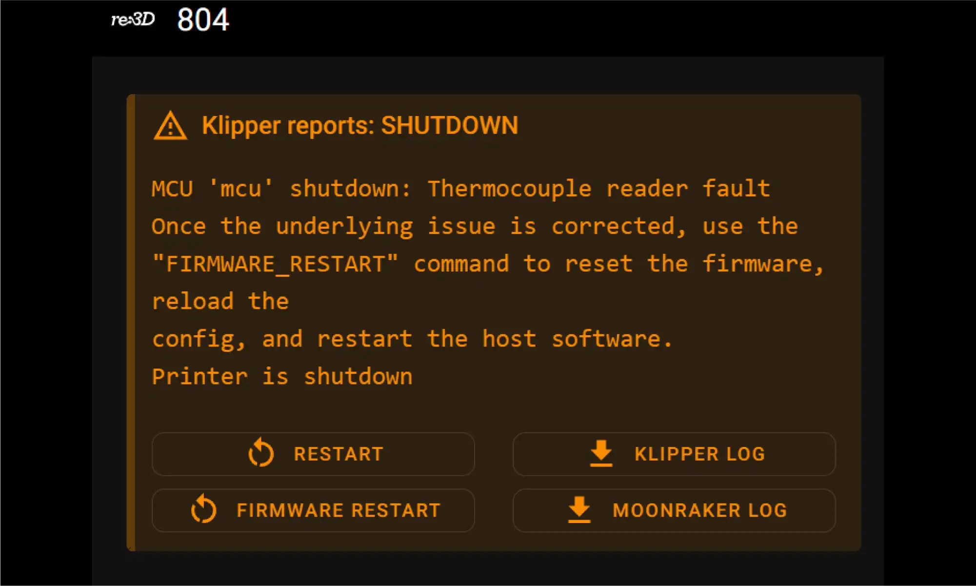
Figure 1: “MCU Shutdown” error thrown by Klipper due to a fault registered on the MAX31856 thermocouple chip.

re:3D’s uses the Archimajor 3D printer motherboard from US manufacturer UltiMachine (South Pittsburg, Tennessee). The Archim boards use a MAX31856 chip from Maxim Integrated to amplify and digitize the input signals from the thermocouples, and it was this chip that was throwing the pesky error. Buried in an obscure Maxim FAQ was a cryptic comment about shunting the negative lead of the thermocouple input to ground to improve performance. The engineering team tried it out (Figure 2), and this has reliably prevented the error from occurring. re:3D now has a field-fix available for service technicians to use when encountering this issue on customer machines and is also working with UltiMachine to incorporate this feature into future versions of the motherboard.
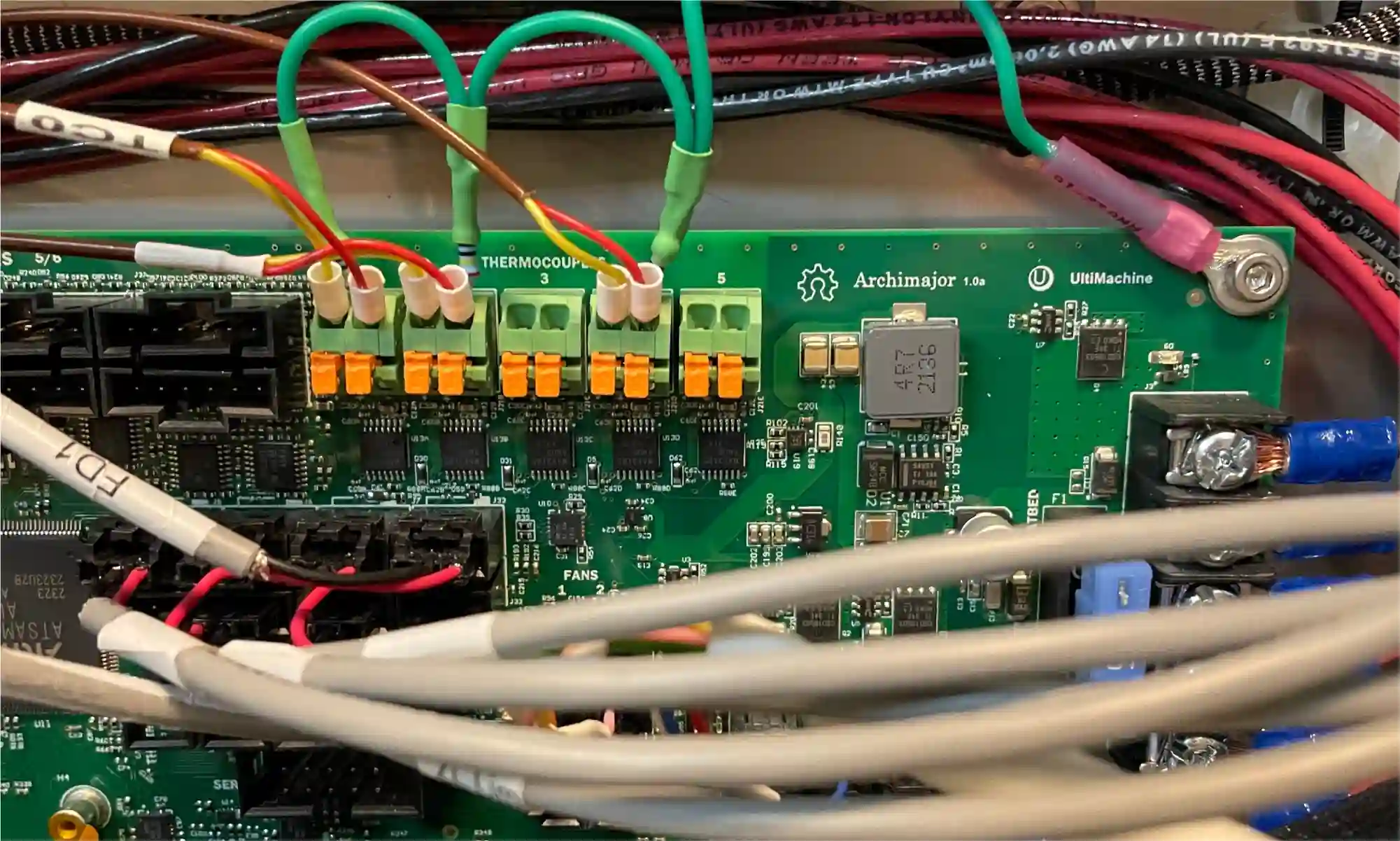
Figure 2: Shunt resistors installed on the thermocouple inputs.

Terabot Hot End Conversion

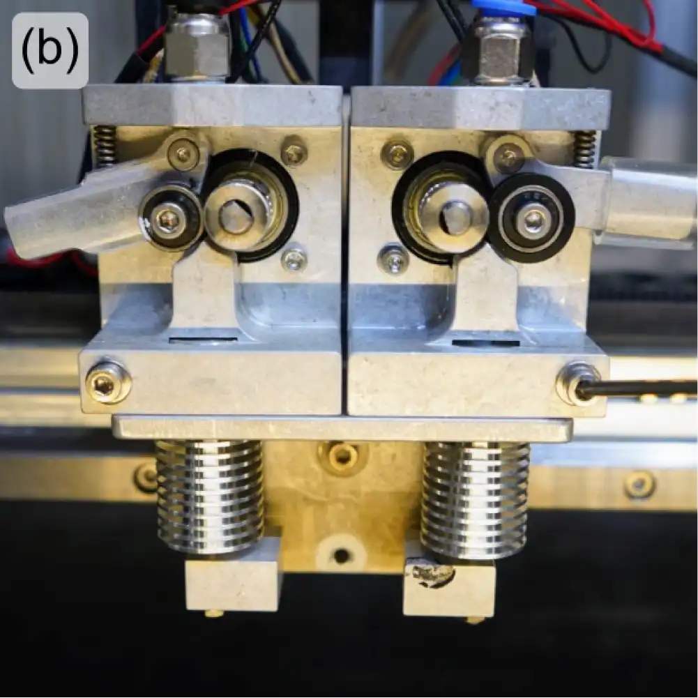
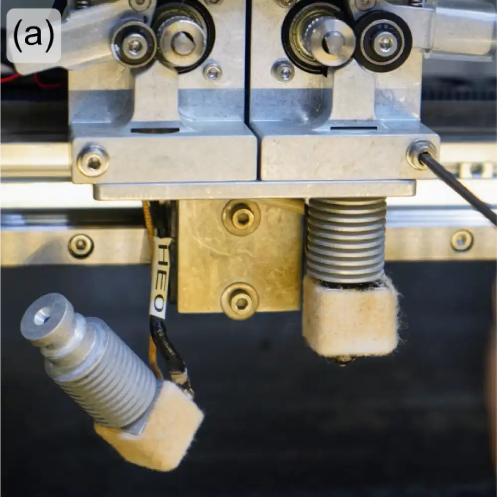
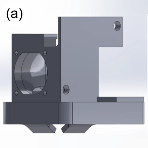
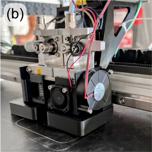
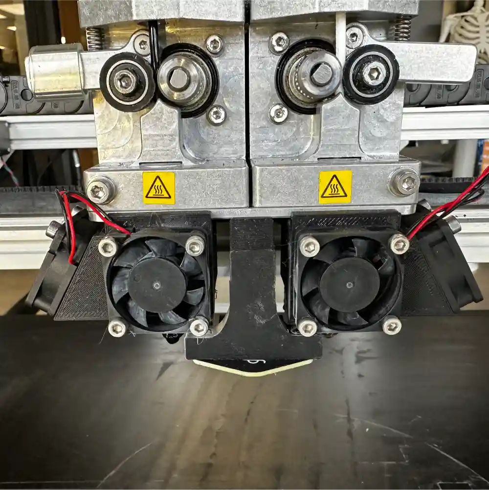
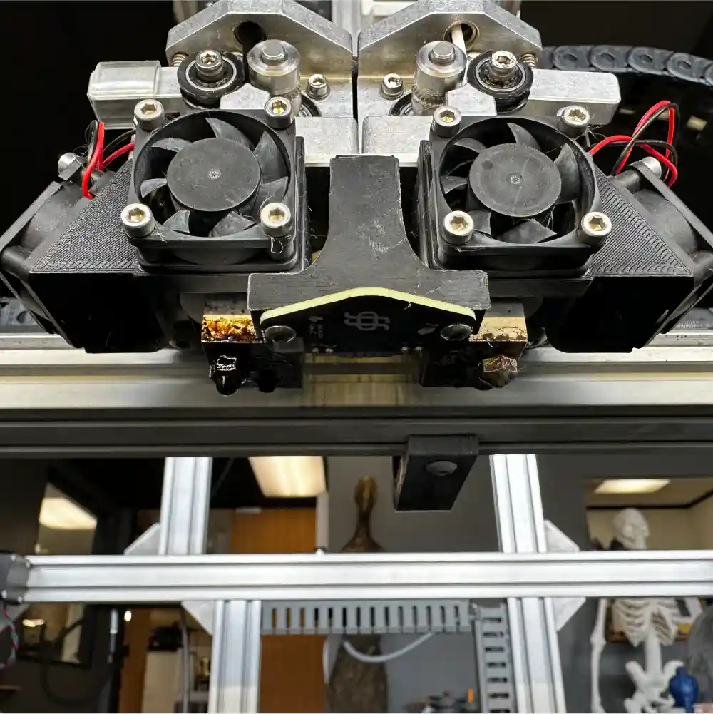
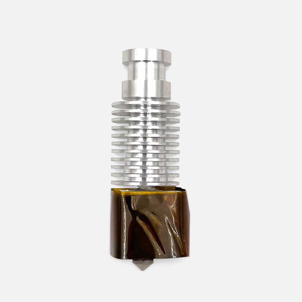
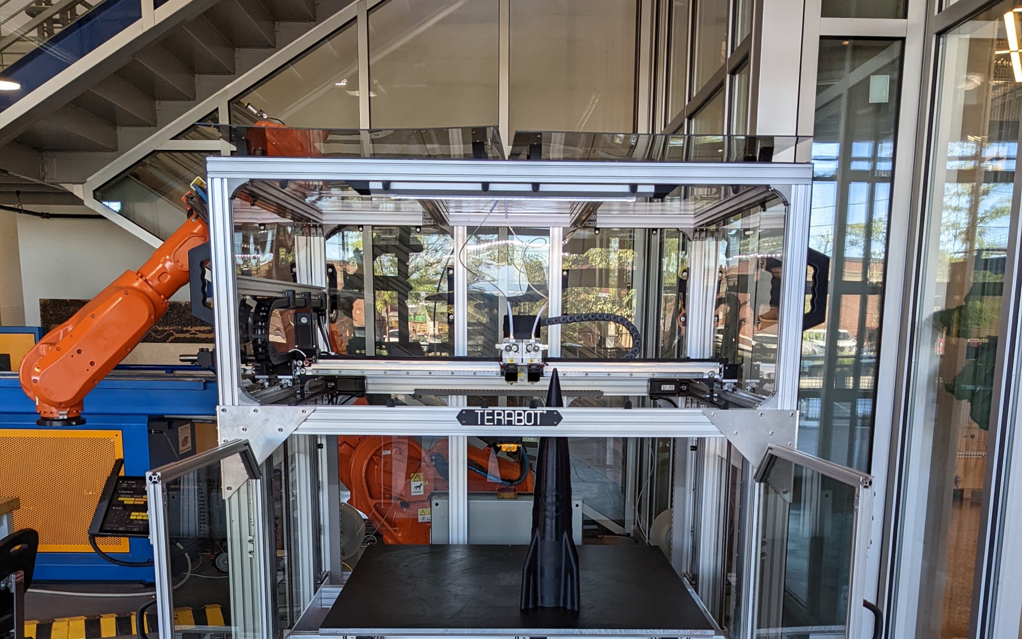
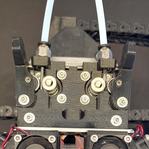
re:3D has a long history of designing and testing extruders and hot ends, always looking for ways to push more plastic to print faster. (OG members of the re:3D community might remember the early “Mondo” hot end prototype.) To keep up with its larger build volume (915 x 915 x 1000mm), re:3D’s Terabot filament printers have been shipping with “20 Series” hot ends, which have a larger heater block to increase the residence time of the plastic within the heat zone and speed the melting process (Figure 3). However, testing has shown that with the proper slicer and configuration settings, re:3D’s standard hot ends perform equally well and are less prone to occasional inconsistent flow or leaking at the nozzle.

To improve overall performance and reliability, Terabots will now be supplied with standard hot ends. This is a minor engineering change, and the Customer Service team has developed a simple and easy-to-install upgrade kit that requires no major modifications to existing Terabot platforms. The Customer Service team is looking for initial Beta Testers for the Terabot hot end conversion kits. If you are interested, you can read more about re:3D’s Beta Testing Program below.

Figure 3: Comparison of 20 Series hot ends (a) and standard hot ends (b) installed on a Terabot.

The GigabotX FGF (Pellet) Platform

There has been progress on both GBX part cooling and GBX bed mesh compensation, but the Gigaboss leading those efforts is busy finishing his master’s thesis, so you’ll have to hold off until next time for a written update. Do worry – it’ll be worth the wait.

Software Improvements

re:Bugger

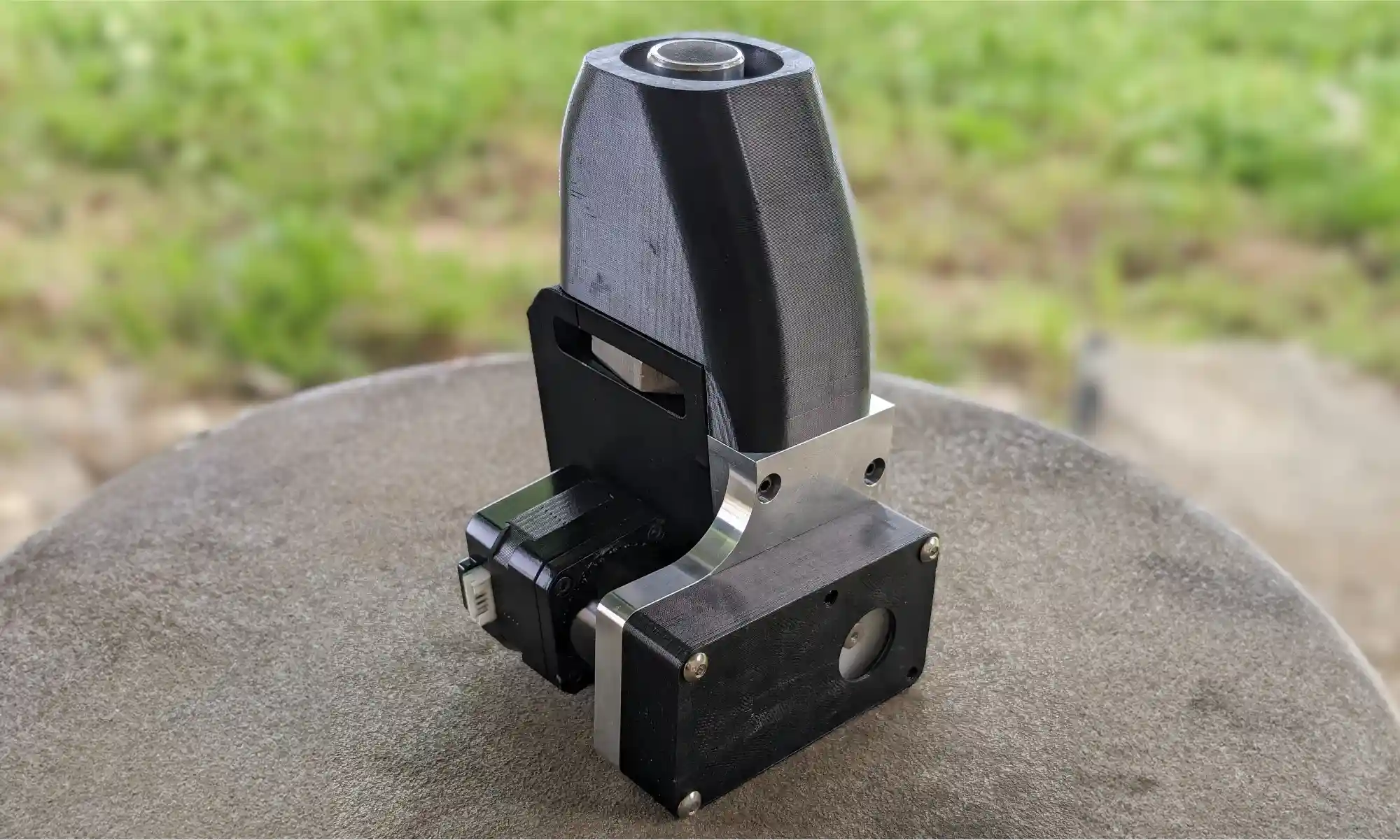
This spring semester, re:3D has been pleased to host Yasseen Hilal, who is studying computer science at the University of Texas, as a software engineering intern. Yasseen took on the task of developing a printer debugging tool for use in the field. The re:Bugger (Figure 4) simply plugs into a Gigabot 4, Terabot 4 or GigabotX 2 via a network cable, then through a simple and intuitive interface reads the available log files to detect errors and provide possible solutions. Log files and performance graphs can be easily exported from the printer onto a USB drive for later review, and the re:Bugger also allows users to flash the latest printer firmware onto the Raspberry Pi without needing network access. This all helps reduce printer downtime.

Yasseen did a great job on his project, and the re:3D team wishes him all the best on his future endeavours.

Figure 4: The re:Bugger printer debugging tool.

Bed Mesh Compensation

There was recent feedback on accuracy and standard operation being manually intensive. Updates have since been made on the mesh compensation workflow which will now carry out a startup procedure to automatically calibrate the Z offset, tram the Z lead screws, and adaptively probe only the area where the part is printing.

This new workflow is meant to keep manual efforts to a minimum during calibration. This procedure is written into Klipper as a comprehensive macro and can be called at the beginning of a print using a single line of Gcode in the slicer.
This master macro approach makes usage simple for the end user while also ensuring accurate and standardized results. There are also optional advanced parameters for users who want to fine tune and experiment with values.

  • Procedures:
  • Prime the extruder
  • Clean the nozzle for accurate offset calibration and probing
  • Model calibration
  • Z offset Calibration
  • Z tilt calibration
  • Adaptive probing

We are actively seeking feedback through our beta testing program, and encourage new testers to contribute their insights to further refine and improve this workflow. You can learn more about re:3D’s Beat Tester Program below.

HELM

Work also continues on HELM, the printer fleet management software under development at re:3D. There have been some minor changes under the hood since the last update, but the most obvious improvement is the user interface – it’s cleaner and easier for casual operators to use (Figure 5). This is an open-source project, and you can try the application yourself, report problems, contribute, or follow progress here: Helm on GitHub.
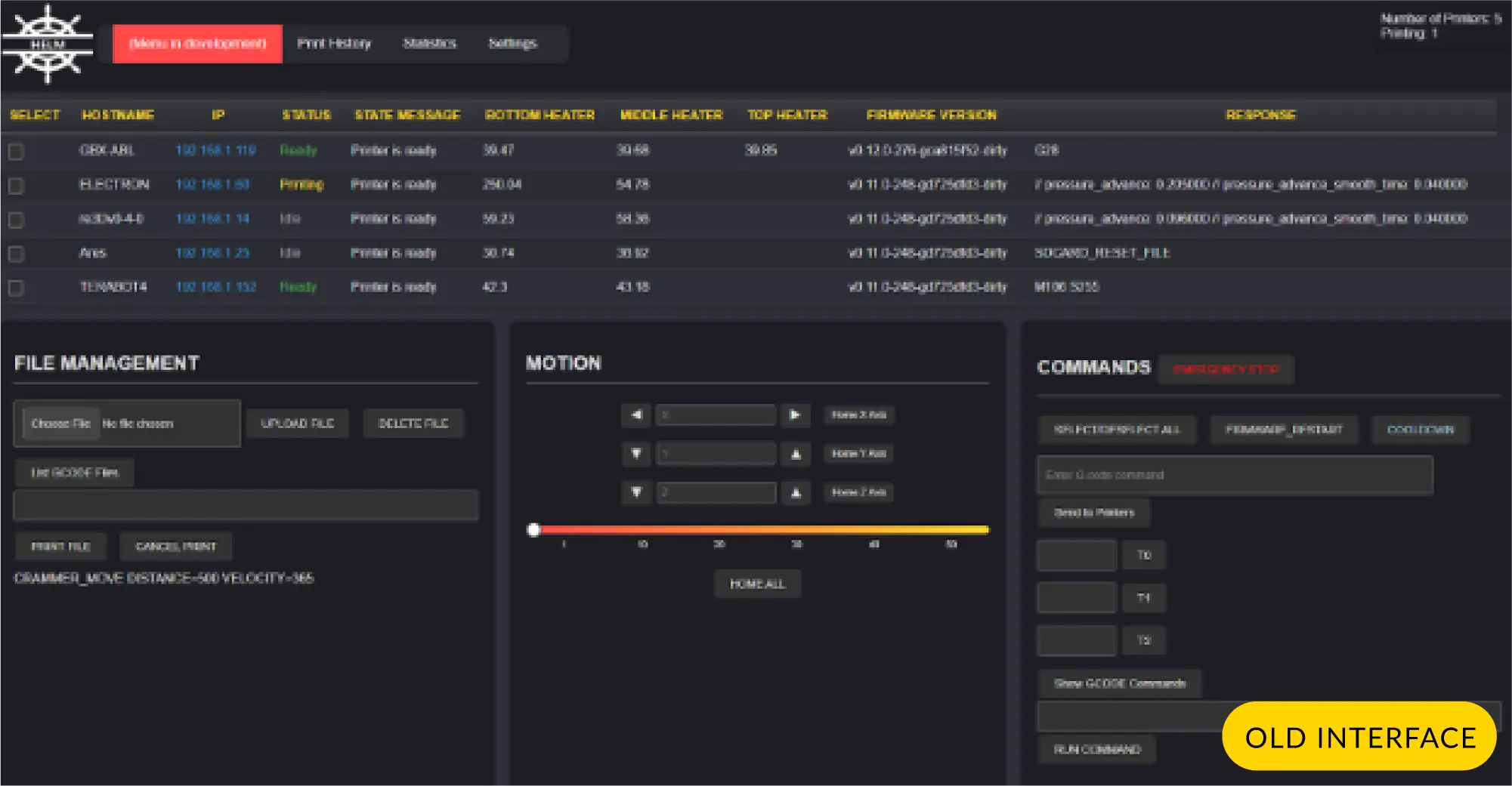
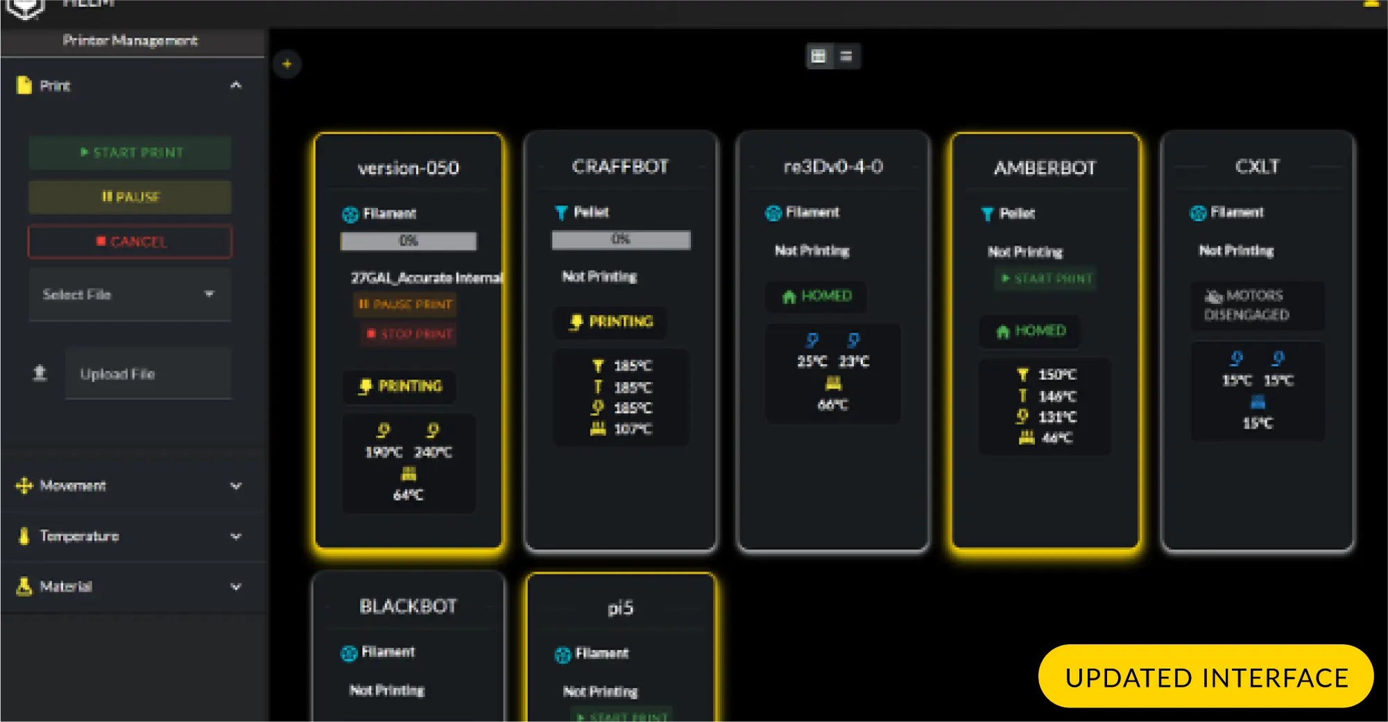
Figure 5: Comparison of the HELM GUIs - older version on top, updated version on bottom.

Beta Testing Programs

As an open source company, re:3D celebrates collaboration with our community of users, customers and vendors. Historically, select new changes or features were offered to existing customers for ‘beta testing’ as part of re:3D’s internal engineering process. The Beta Testing Program has since evolved and become more formalized with contributions from engineering, customer service and sales and marketing. An application form is now available on the re:3D website here where you can apply to be a beta tester through the following steps:

1. Choose Your Desired Beta Product/Software

Read a short summary of available beta products with how it will improve the Gigabot user experience. Ideally, applicants will have non-modified printers so that the performance improvements of the beta products can be accurately assessed.

2. Sign Up

Fill out a Google Form to express your interest in beta testing the selected product for which you’d like to be considered.

3. Confirm Acceptance

A notification email will be sent to confirm your selection as a beta tester. This will include a beta tester release agreement, a defined testing period, steps on how to submit feedback, and a link to the Forum for updates on these products. Invoicing and delivery information will also be requested, then the beta products will be shipped.

4. Begin Testing

An Instructional Guide with detailed installation instructions and troubleshooting tips will be provided with the beta products.

A Google Form will be sent to beta testers no less than monthly for each product to solicit feedback and recommendations.

5. Be a proud GigaTester!

For now, there are two beta test products available for consideration:

  • Bed Mesh Compensation (Gigabot 4 only)
  • Terabot Hot End Conversion (Terabot family)

Watch for these additional beta testing opportunities in the coming weeks:

  • Bed Mesh Compensation (GigabotX 2 only)
  • Feedstock Crammer (GigabotX family)
  • 1.75mm Filament Conversion Kit (Gigabot / Terabot family)
  • GBX Part Cooling (GigabotX family)

R&D Programs

Though there has been recent turmoil and uncertainty in the news about federal research grants, re:3D continues to support R&D contracts for the Department of Defense (DOD), NASA, the Department of Energy (DOE) and the National Science Foundation (NSF). Some of those projects went along on re:3D’s recent trip to Hawai’i, but the others have been making progress too!

ReCreateIt (NSF)

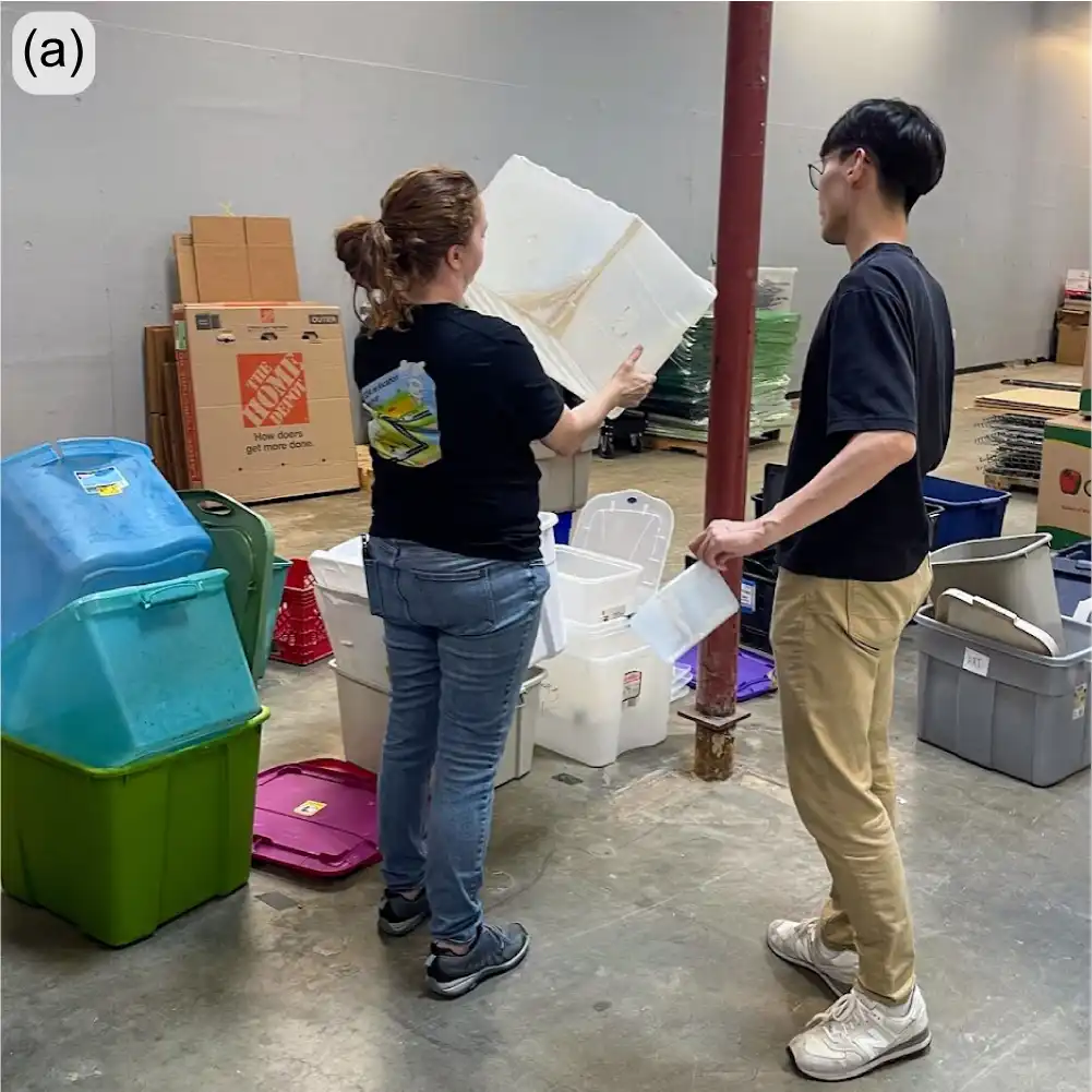
ReCreateIt is a multinational initiative led by re:3D, with a goal to transform waste plastic into valuable products through 3D-printing and community-led design. To achieve this mission, re:3D is collaborating with the Austin Habitat for Humanity ReStore, where a Gigalab was designed and delivered in December 2024. Since its delivery, the Gigalab has been outfitted with a granulator, pellet/flake dryer, a GBX2 XLT, all necessary mechanical and electrical tools, and personal protective equipment. The long-term goals of the ReCreateIt Gigalab is to recycle and reuse over 10,000 lbs of local plastic waste over its lifetime while being a net-zero energy manufacturing lab.

Compared to other Gigalabs, the ReCreateIt Gigalab will feature various additional sensors that monitor temperature, humidity, emissions, particulate matter, and energy usage. The sensors will allow the team to construct a comprehensive model of the Gigalab system and quantitatively assess the environmental impact of the Gigalab and the recycling efforts. This data may also provide the re:3D team with insights that may spur redesigns and improvements of future Gigalabs towards more energy-efficient and sustainable systems.

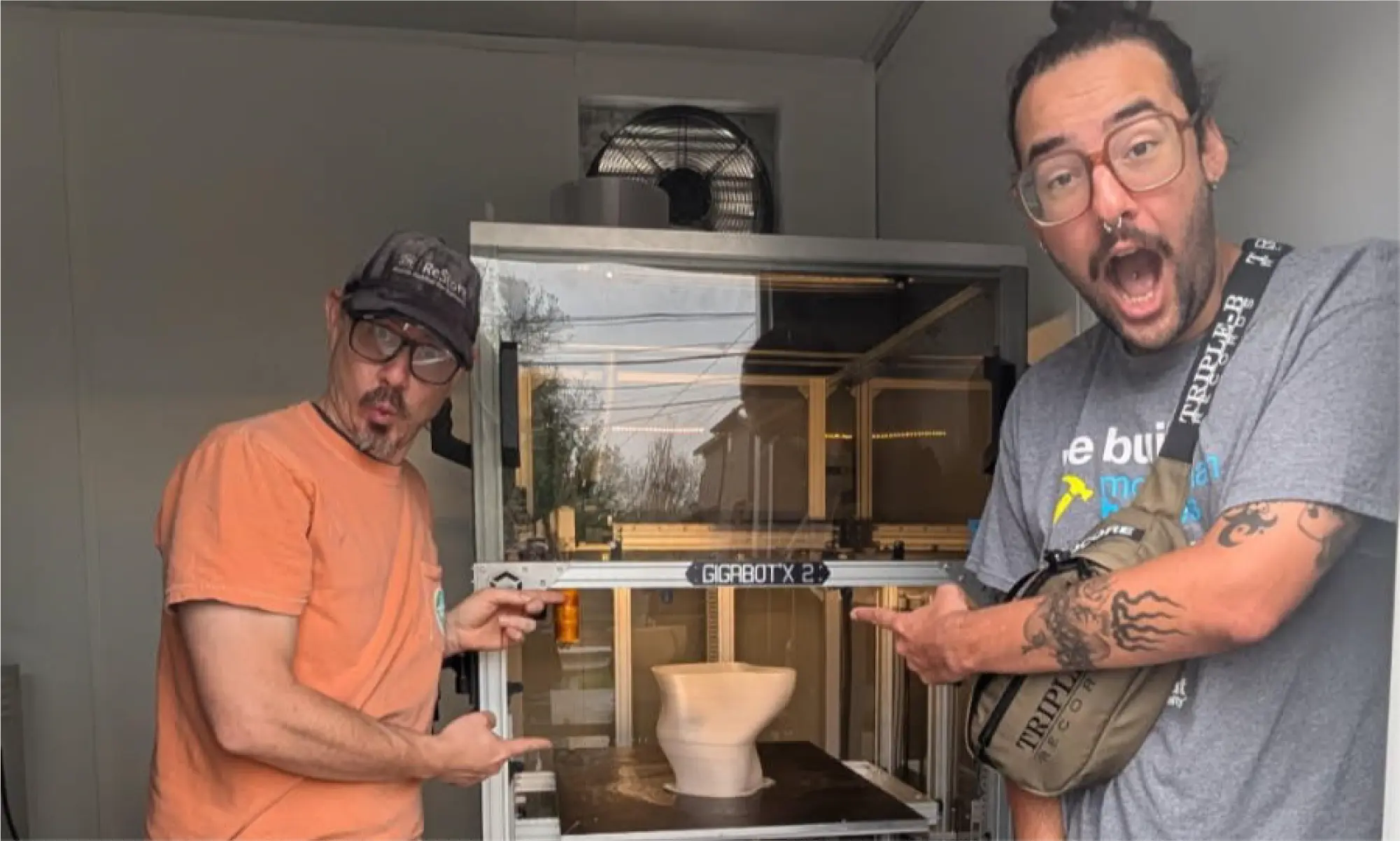
To support daily operations, three Gigalab associates have joined the team to collect and sort incoming waste plastics, and to operate the machinery that processes and prints with the recycled materials. The re:3D team is actively mentoring the associates to enable them to operate and troubleshoot the Gigalab equipment safely and autonomously (Figure 6).

Figure 6: Gigalab associates celebrating the first print of the ReCreateIt Gigalab!

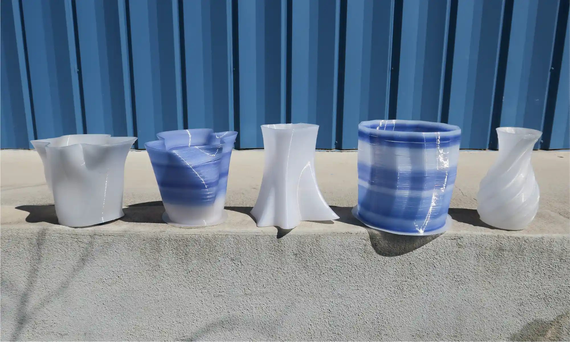
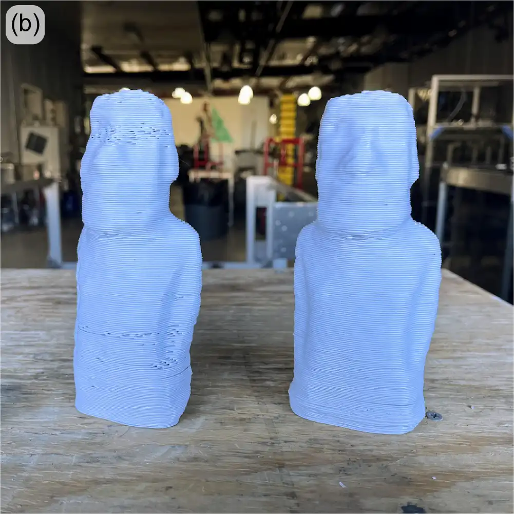
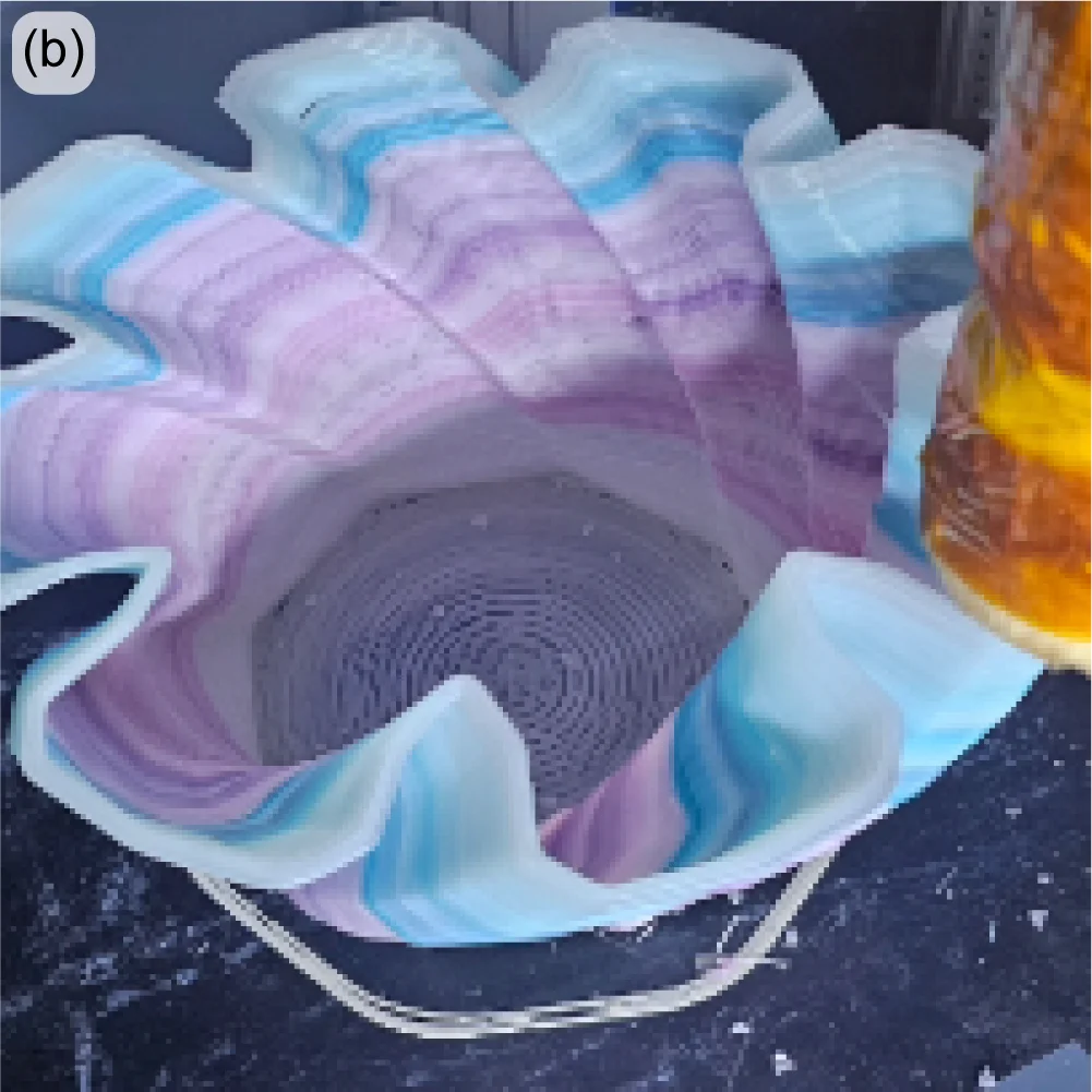
There have also been advancements in 3D printing with recycled polypropylene (PP) — the second most used commodity plastic in the world. In fact, the vases shown in Figure 7 below are printed from 100% recycled PP, which were originally storage bins collected at the ReStore that were destined for the landfill. While there still are challenges to scale up into furniture pieces such as end tables or stools, achieving successful and functional parts using 100% recycled material, without any additives or blending agents, is a significant milestone in sustainable manufacturing.

Figure 7: Vases printed from 100% recycled polypropylene (PP).

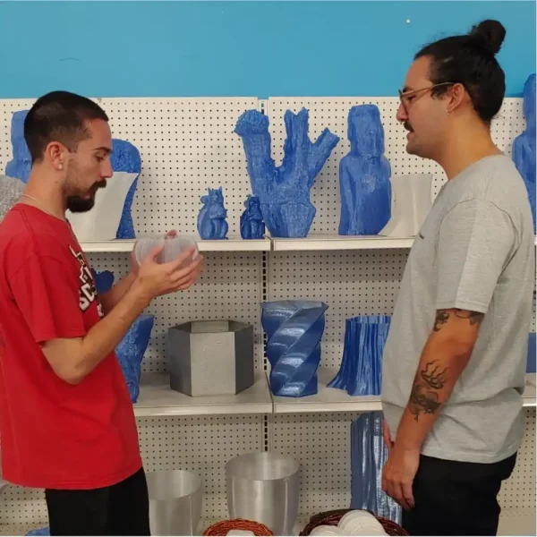
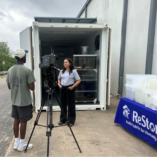
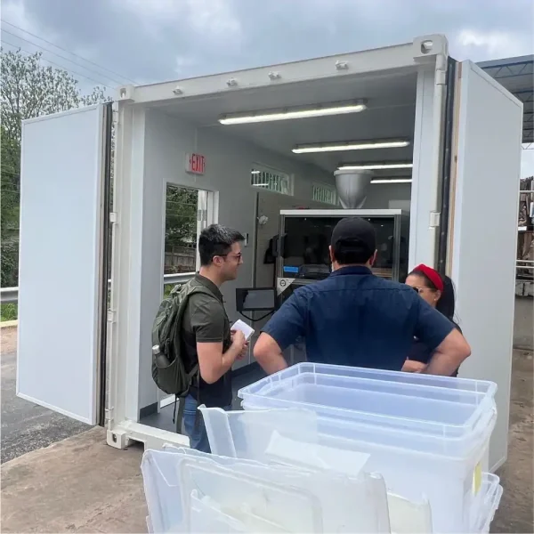
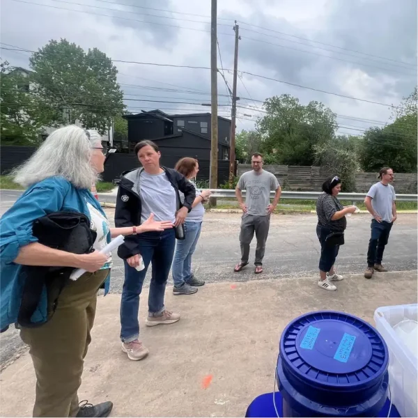
To showcase the progress on the project to the public and local media, the ReStore and re:3D teams co-hosted a soft opening at the ReStore on April 19. Well over a hundred curious customers stopped by to take a look at a large array of printed parts made from recycled materials. Attendees were invited to share their ideas for future products, offer feedback on existing prints, and learn more about the environmental and social impact of the initiative. The majority of visitors also expressed major interest in the behind-the-scenes of the project and participated in tours of the Gigalab, where they got a first hand look at the recycling and manufacturing process including the GBX2 in motion.

Figure 8: ReCreateIt Soft Opening at the AHFH ReStore.

If you’re in the Austin area, stop by the ReStore at 500 W. Ben White Blvd where you can check out the prints in person, buy a piece printed from recycled waste and directly participate in the circular economy yourself.

“Bigger, Better, Faster” FGF (DOD/US Army)

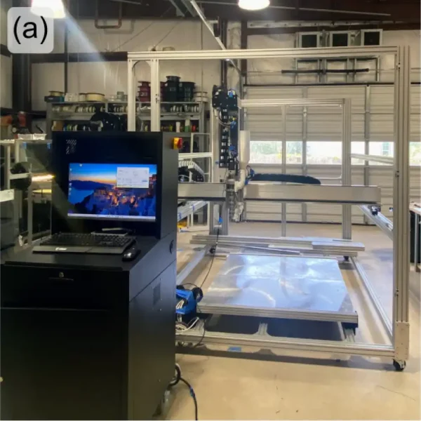
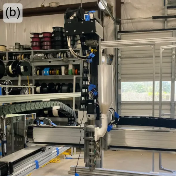
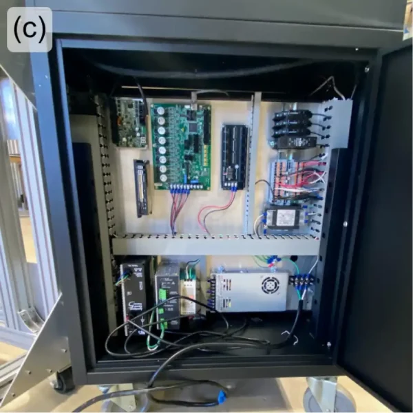
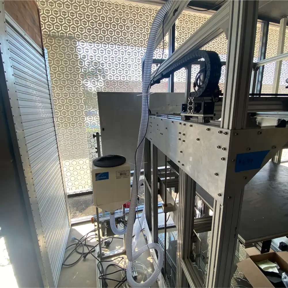
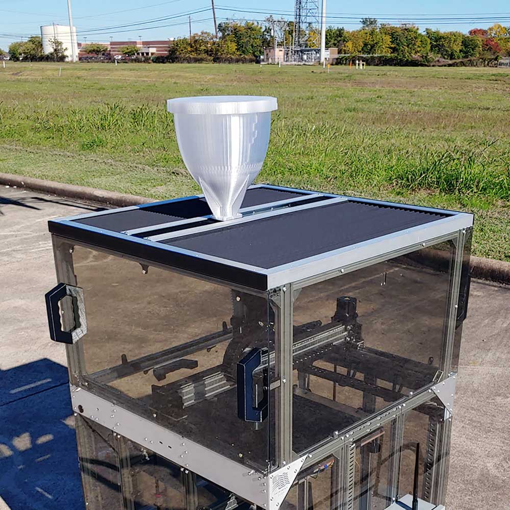
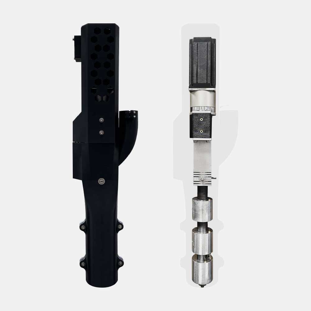
The large FGF printer being developed under a US Army SBIR R&D award has come a long way since the last update. The frame is complete, and the linear motion components – including ball screw actuators and servo motors – are installed and commissioned (Figure 9(a&b)). Another major change from re:3D’s traditional build style is the use of a separate HMI (human-machine interface) and control pedestal (Figure 9(a&c)), rather than having an electrical box and touchscreen interface mounted directly to the printer’s frame. Not only does this change allow for the room needed for added servo motor controllers and power supplies, it makes the electrical and control components more accessible for service. Having a full computer built into the HMI pedestal will allow users to access third-party software when necessary for servo motor diagnostics, along with providing opportunities for performing CAD and slicing tasks at the same workstation as the printer operation, without requiring network access – which is not available or desirable in some situations.

Figure 9: Printer frame with HMI/control pedestal (a); extruder mounted on z-axis actuator with temporary side hopper (b); inside view of HMI/control pedestal during initial wiring (c).

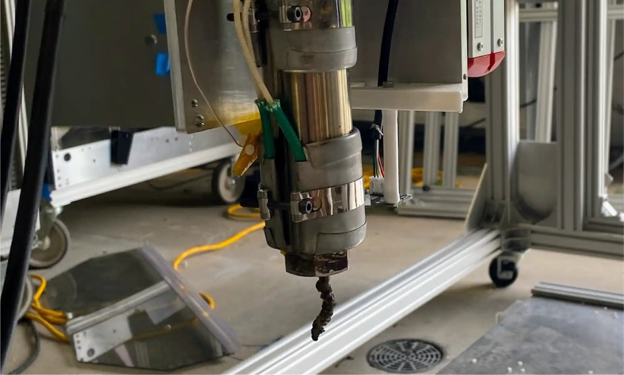
After commissioning and initial tuning, the printer’s extruder was finally tested. This is a novel and exciting new design from Dr. David Kazmer’s group at the University of Massachusetts Lowell, who are collaborating with re:3D on this effort. After a few hiccups caused PLA to thermally degrade inside the barrel, DynaPurge became the first material extruded through this system. As shown in Figure 10, the first extrusion looks like – well, you know. But it’s a first extrusion nonetheless, and the team is excited for the rapid progress of this project.

Figure 10: First extrusion! No judgments, please.

Additively Manufactured Thermal Protection Systems (NASA)

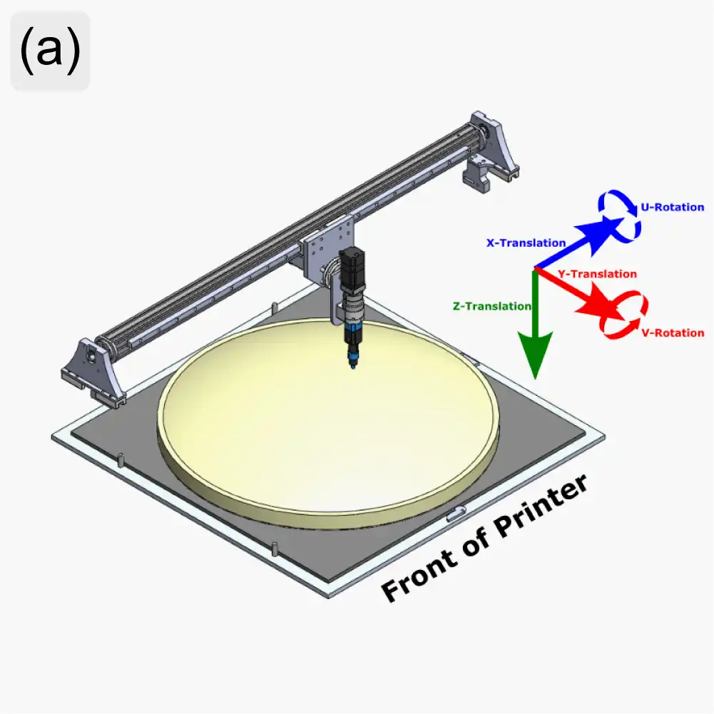
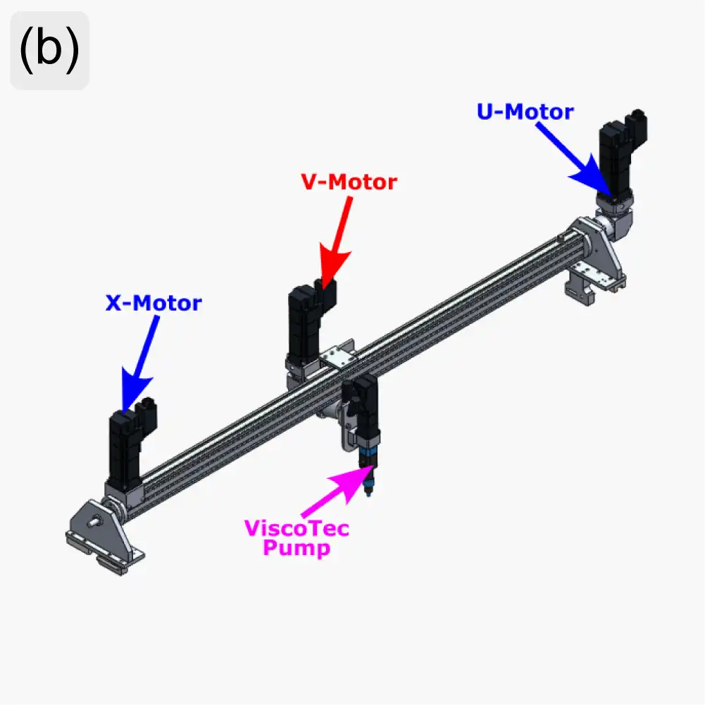
re:3D’s R&D team designed and built a 5-axis printer to deposit ablative foam materials onto non-planar surfaces. This has been done before using robotic arms, but this is a unique design based on a gantry system, intended to investigate the economy of a different kinematic approach to conformal printing. The frame and x, y and z axes systems are similar to re:3D’s Terabot printer. But to add the extra degrees of freedom, the extruder (a ViscoTec volumetric deposition pump) rotates about the Y-axis, and the whole bridge rail rotates about the X-axis (Figure 11(a&b)).

Figure 11: AMTPS printer axes definitions (a) and motor locations (b).

Rather than adapt the Archimajor motherboard for 5-axis control, re:3D collaborated with the Siemens team at the Charlotte Advanced Technology Collaboration Hub (CATCH) to implement an advanced industrial control system. The CATCH team helped identify appropriate servo motors and control hardware for the printer, and also provided training both at a partner solution provider’s site in Houston and at their own Machine Tools facility in Elk Grove Village, Illinois.

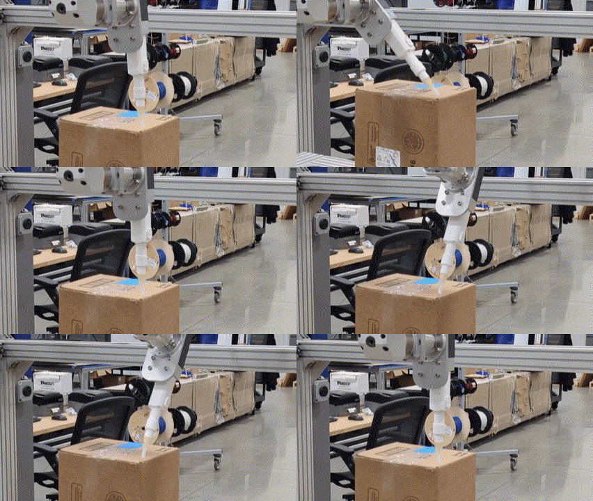
For the final touches and commissioning of the printer, the system was sent to Bobby Cole and his team at Think-PLC in Lexington, North Carolina. Think-PLC is a Siemens Solution Partner, and Bobby is highly regarded in the world of industrial controls and automation for his work with machine builders and manufacturers, and re:3D’s experience bears this out. Think-PLC identified and corrected some deficiencies in the AMTPS printer after they received it, then worked to understand the system requirements and implement control kinematics to achieve optimal performance within the limitations of the printer’s mechanical design. It has been great working with them and watching the printer come to life (Figure 12). The AMTPS printer will soon be returning to re:3D in Austin for the installation of the deposition system and the beginning of print testing.

Figure 12: AMTPS printer demonstrating a range of kinematic motion at Think-PLC’s facility in North Carolina. (Credit: Think-PLC)

Another collaborator on this project is Addiguru, a software company that specializes in in-situ monitoring technologies for additive manufacturing processes. While re:3D is designing a mounting system for multiple cameras to monitor the deposition of the TPS foam onto the substrate (Figure 13), Addiguru is developing the software to measure the width of the extrusion and flag excessive variances in volumetric deposition in real time. Although it won’t be implemented within the scope of this effort, future work on this project could incorporate Addiguru’s software to provide feedback into the Siemens system for closed-loop control of the deposition process.

Figure 13: Three-camera mount system providing full video coverage of the ViscoTek deposition nozzle.

Water Bottle Granulation (DOE)

The collaboration with Oak Ridge National Laboratory (ORNL) continues with a focus on separating the recycled PET (rPET) flake from granulated water bottles out of the flake/water slurry coming from the granulator. ORNL is procuring a hydrocyclone for the separation step. Hydrocyclones produce opposing vortices within a chamber which force large, heavy particles out through a reject port and lift lighter fines and liquid out through the overflow. The physics of hydrocyclones is quite interesting and watching YouTube videos about them can easily burn a couple of hours from your day.

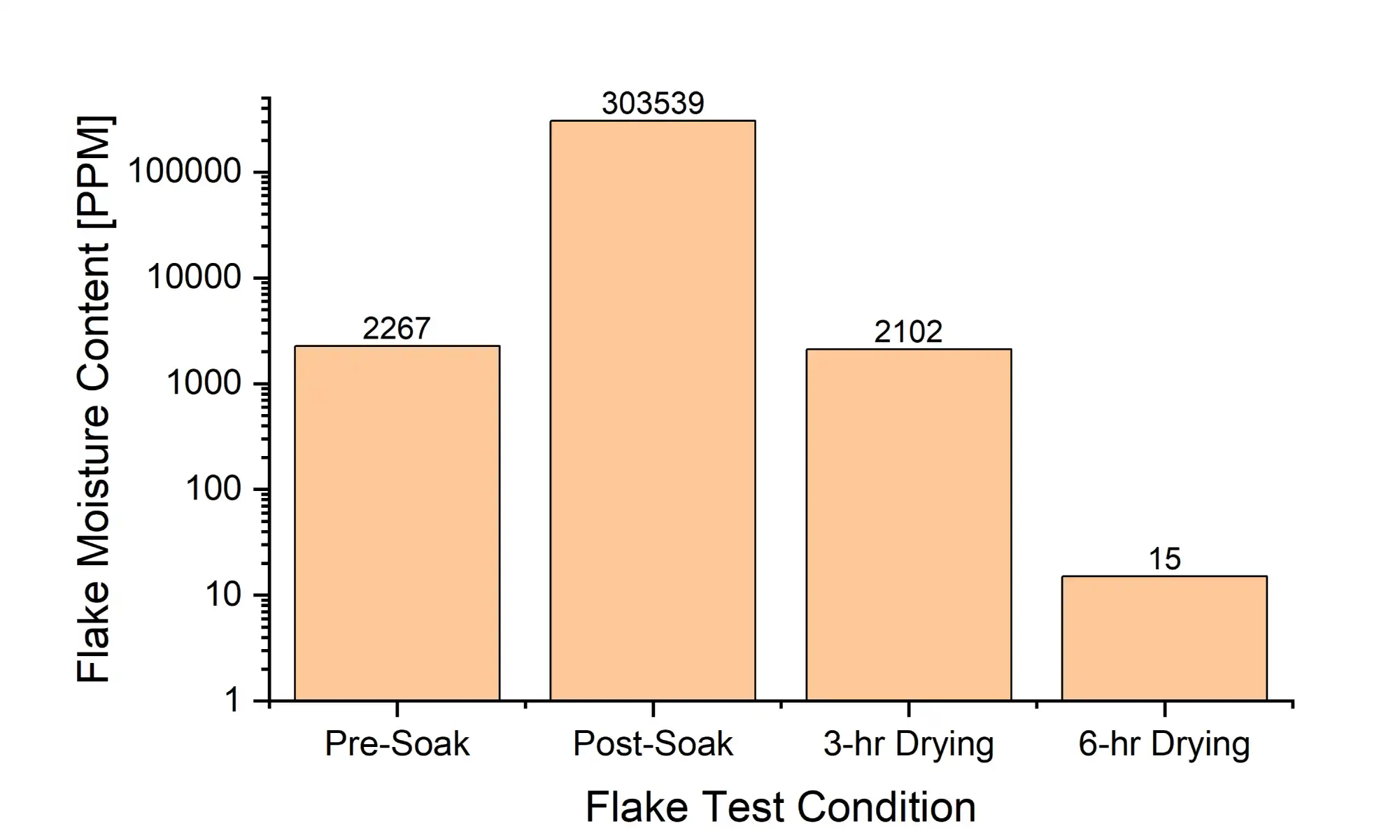
Once the rPET flake is separated from the water it must be dried, and re:3D has been studying the efficacy of desiccant drying on wet flake. A sample of granulated water bottles was soaked in water overnight, then dried in an industrial recirculating desiccant dryer at 70°C. The moisture content of the flake was measured using gravimetric analysis (i.e., loss on drying) at multiple steps throughout the process. As shown in Figure 14, as little as three hours is required to dry the flake back to its original, equilibrium condition, and an additional three hours may be sufficient to dry the flake sufficiently for immediate extrusion processing (below 200 PPM). These results are consistent with re:3D’s previous tests on “Drying rPET Water Bottle Flake”.

Figure 14: rPET flake moisture content measured throughout a water soaking and drying process.

It’s a bit of a chore to collect, edit and format the information and photos telling re:3D’s behind-the-scenes technical stories, but it’s also incredibly fulfilling to be able to share the good work going on here and appreciate the cool factor in what we get to do every day. All in all, it’s worth the time.

Thanks for reading along, and as always… Happy Printing!

Patrick, Chris, Mitchell, Taylor

Blog Post Authors

Engineering Updates – 3D Printing, Part Cooling, Firmware and More!

re:3D was on the move last year – literally. But the crew has settled into the new Austin facility with a continued passion for tackling the challenges of additive manufacturing. New faces have joined the Engineering and R&D Teams, and they have all been making impressive progress during the sometimes messy results of a relocation. This is a long-overdue look at some of their recent work.

Early last year there was a company-wide exploration of how and why ‘filament grinding’ was affecting our customers. Follow-up work has focused on cooling methods – both for the extruder mechanism and for part cooling. Improvements in cooling the extruder heat break reduces filament softening (i.e., “heat creep”) in low-temperature materials such as PLA which is a contributing factor to grinding and ultimately print failure. Other thermo-mechanical properties of the extruder are being evaluated as well, with the goal of better thermal management of the filament for more reliable extrusion. Upgrades to part cooling are also being tested. For many thermoplastics, the goal is to extrude above a certain temperature and let the polymer bond to the previously deposited layer (if there is one), and then solidify to maintain the desired geometry as the nozzle travels onward. The rate at which the plastic hardens affects how fast the nozzle can travel without compromising the quality of the print. Often, by appropriately cooling the extruded plastic with forced air, the plastic still bonds, but the geometry is rapidly set and the nozzle can travel faster – ultimately completing the print more quickly. Rapid setting of the polymer also allows for improved performance when printing bridges or overhangs.

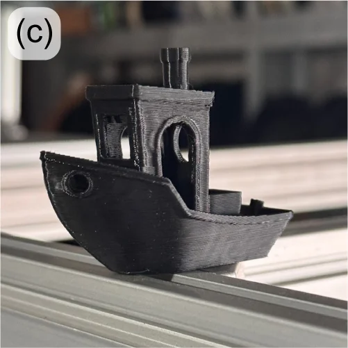
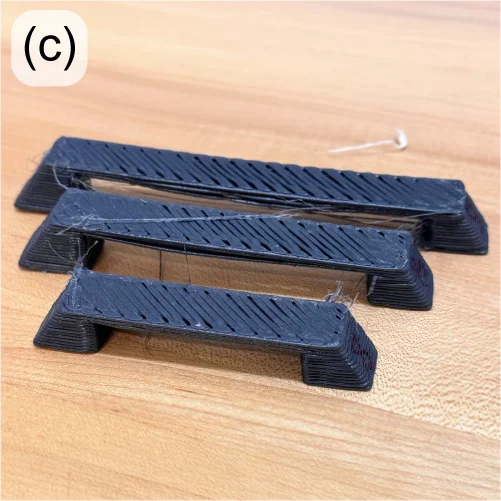
With a new approach to thermal management, small, square axial fans are still used to cool the extruder heat sinks, but radial blower fans are used to provide higher-velocity air at the nozzle tip for part cooling (Figure 1, left and center). With this approach, unsupported overhangs of up to 70° are achieved before scoring “poor” using standard overhang print tests. Print speed can also be dramatically increased. The cooling upgrade allowed a standard 3DBenchy model [1] to be printed in 32 minutes with good quality (Figure 1, right) – down from 70 minutes.

Figure 1: New Gigabot extruder cooling design under test (a-B); 32-minute 3DBenchy printed using upgraded cooling (c).

The Engineering Team is also responding to the re:3D user community’s request for a conversion kit to use 1.75mm filament on their Gigabot printers. The new dual-extruder design has been extensively tested on multiple materials internally and will be sent to external beta testers soon.

Product development on the GigabotX (GBX) in recent months has been focused on a mount for a bed sensor to incorporate bed mesh compensation software correction, along with an implementation of part cooling for the GBX extruder. Bed mesh compensation will be performed with the same eddy current sensor now under beta test on the Gigabot filament machines, but the design challenge is to create a mechanically stiff mount at the end of the long extruder system. As part of this mount, cooling fans and ducting are being incorporated to provide forced-air part cooling. The reasons for part cooling are described above, but with the larger bead sizes on the GBX, the thermal mass of the extrusion is generally larger, and the need for part cooling is even more critical – especially for bridging and overhangs. It can also promote easier breakaway of support material from the print.

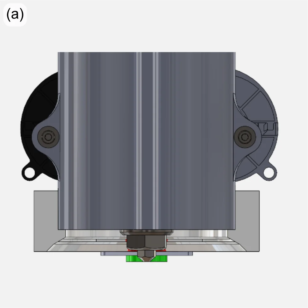
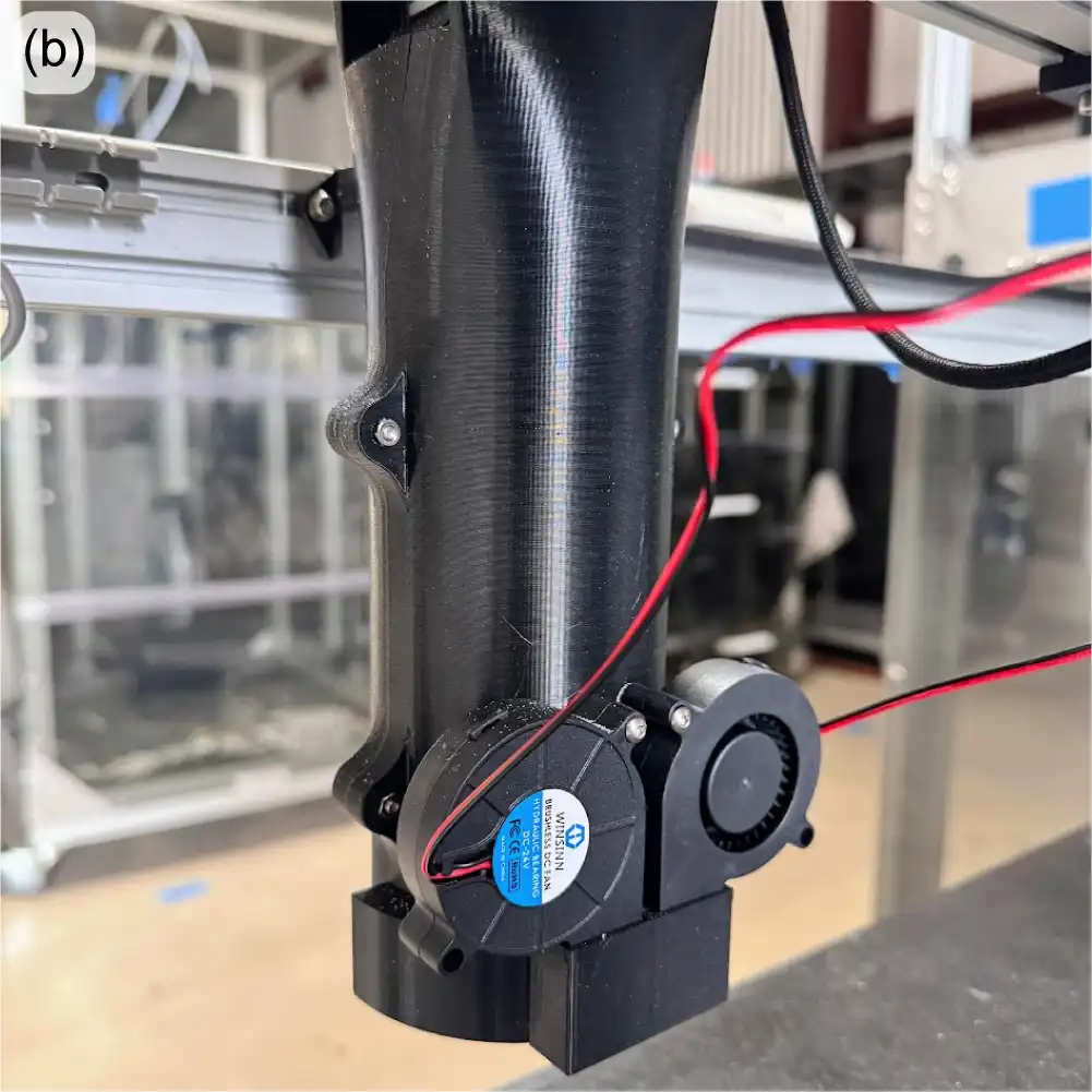
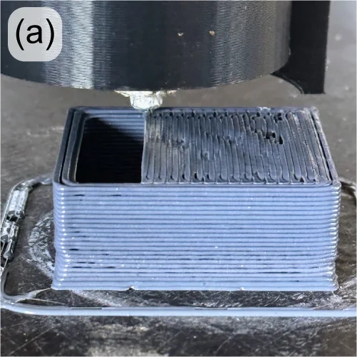
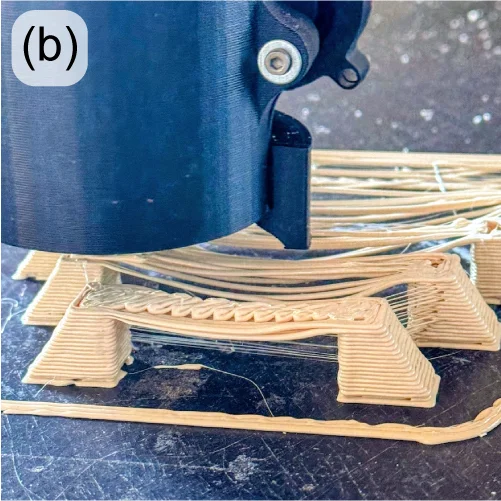
With the part cooling design now under test (Figure 2), PLA is bridging over 40mm with minimal drooping (Figure 3, left) and able to create acceptable bridges and spans over 100mm (Figure 3, right). Overhangs are also improved, and support structures more easily break away by hand, leaving clean parting surfaces.

Figure 2: Experimental mount for a bed sensor on the GBX extruder shown in green (a); GBX part cooling fans attached to the back of the extruder cover (b).
Figure 3: 60mm bridging with part cooling on a GBX (a); poor bridging and spanning without part cooling (b); good bridging and spanning over 100mm with part cooling (c).

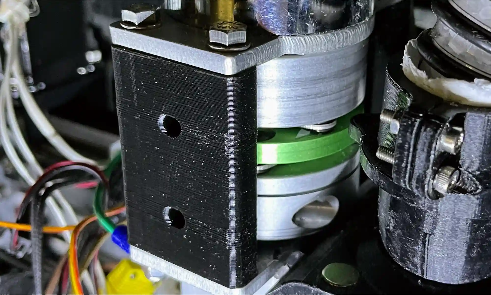
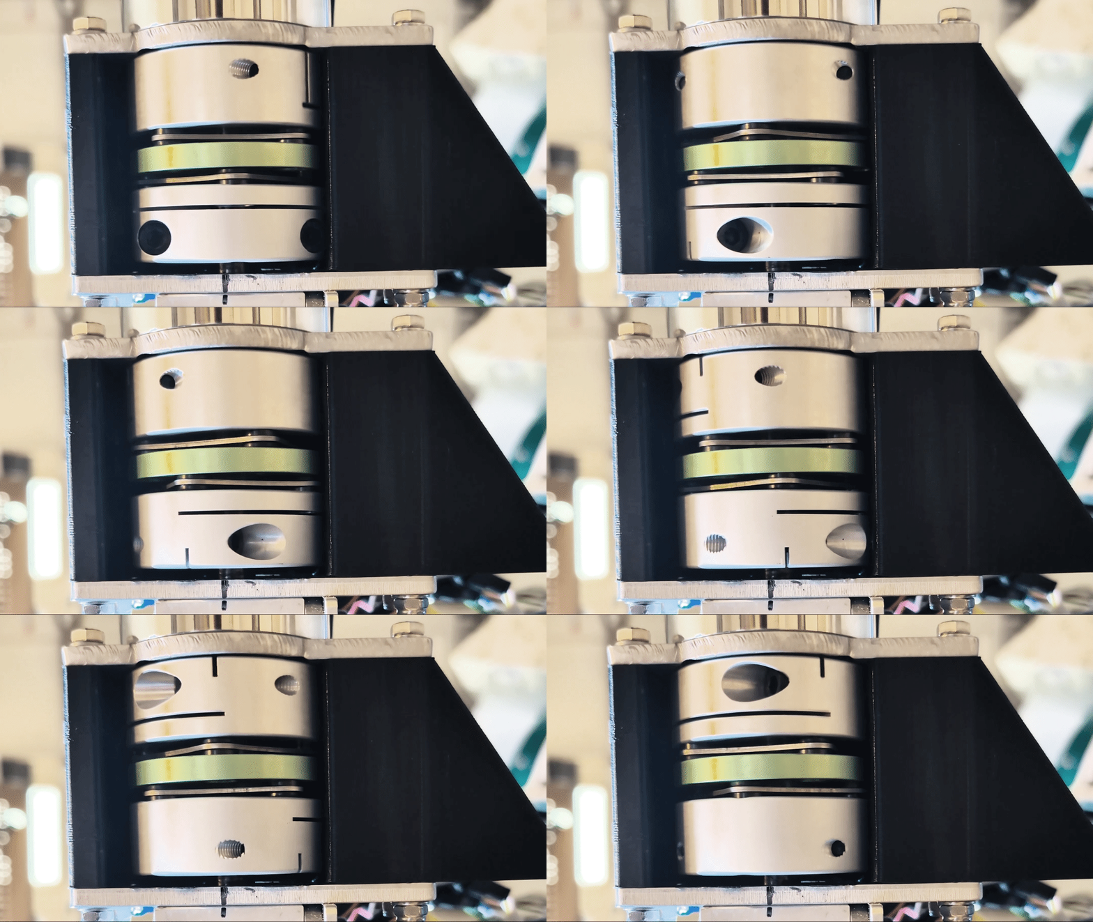
At the other end of the extruder, improvements are underway to improve the reliability and consistency of material throughput. The extruder motor is connected to the extrusion screw through a jaw coupler, which uses a polymer spider interface between two hubs. If overheated or over-torqued, this spider can become deformed, potentially affecting extruder performance. This style of couple also allows for undesirable axial motion of the extruder screw. A new disc coupler is being tested with good results (Figure 4).

GBX disk coupling
Figure 4: New GBX disc coupling under evaluation.

Throughput problems can also be caused when the feedstock (pellets or flake) bridges within the input to the extruder. This material bridging (buildup, jamming, etc) introduces inconsistencies to the flow of material into the extruder which results in underextrusion.

This is more pronounced when using feedstock with irregular morphology and low apparent density (e.g. granulated water bottles), which do not pack tightly or flow well into the extruder under gravity alone.

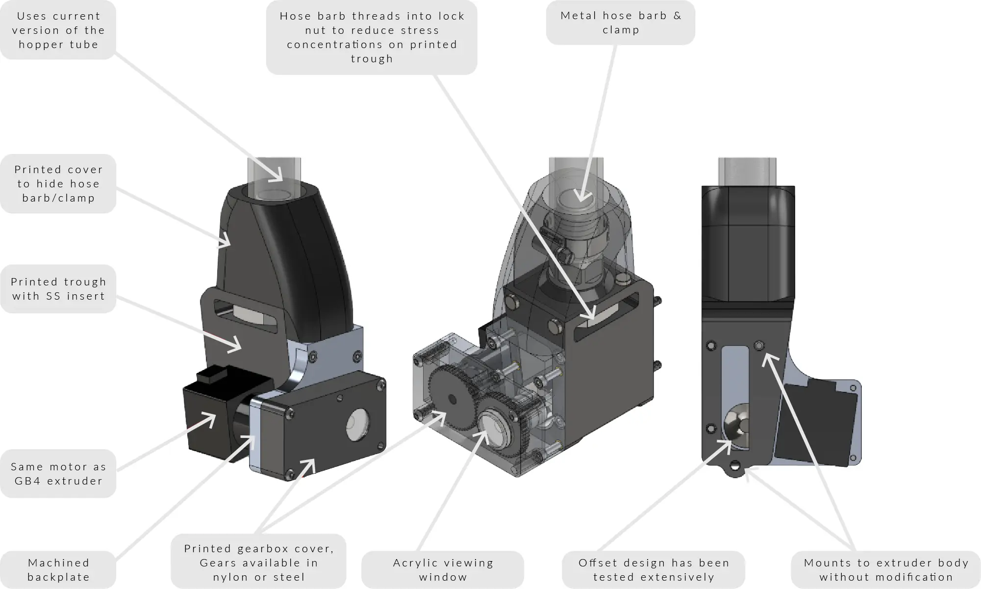
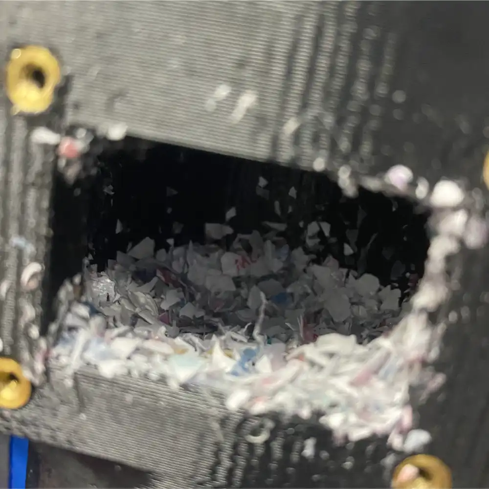
To address this, over 40 versions of a “crammer” that actively feeds material into the extruder have been tested over the years, with the current version called the “beta” crammer (Figure 5). This crammer successfully reduced inconsistencies in the extrusion rate, successfully printing rPET flake at the same rate as rPET pellet. While the crammer showed great potential for printing with irregular flake, unfortunately material bridging still happened upstream from the crammer (at the hopper-hose and hose-barb connections). To take full advantage of the crammer’s abilities, it is important to design a system to reliably resolve material bridging in the feed tube.

Figure 5: Current ‘beta’ crammer design.

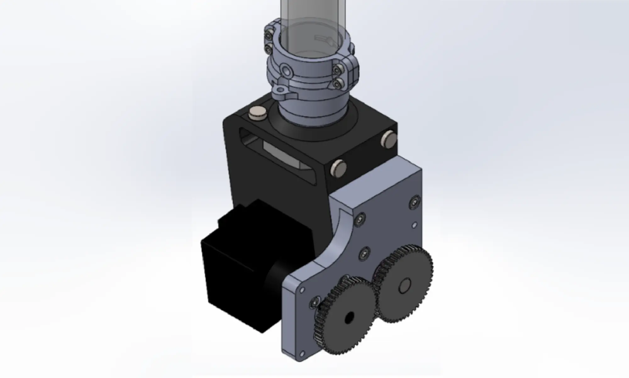
The most important recent design change to the crammer has been to the feedstock hose clamping mechanism. The tubing was originally connected using a metal hose barb and a worm gear hose clamp, similar to garden hoses. Because the hose barb fits inside the hose, the diameter of the feed path decreases at the interface, creating a stepped region that is very prone to material buildup. To address this issue, the hose barb has been replaced with two printed parts that secure the hose from the outside using screws (Figure 6). The new hose clamp design has been tested for well over 100 hours, and showed zero cases of material bridging with all pellets and most flake feedstocks. The flakes that still showed some trouble, including granulated plastic ID cards and shredded water bottles, had particularly irregular morphology due to its original thin thickness.

hose clamp design render
Figure 6. CAD image of new hose clamp design.

For feedstocks with more extreme morphologies, multiple solutions have been considered, including fluidized beds and vibration motors.

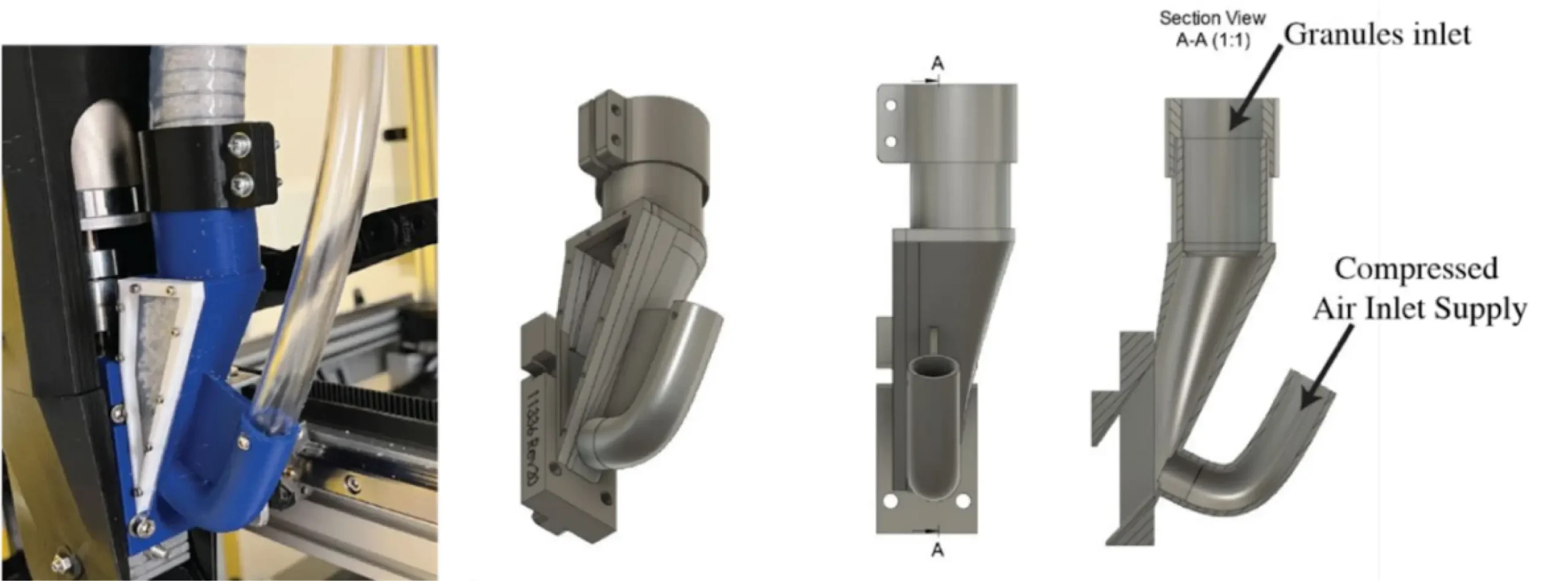
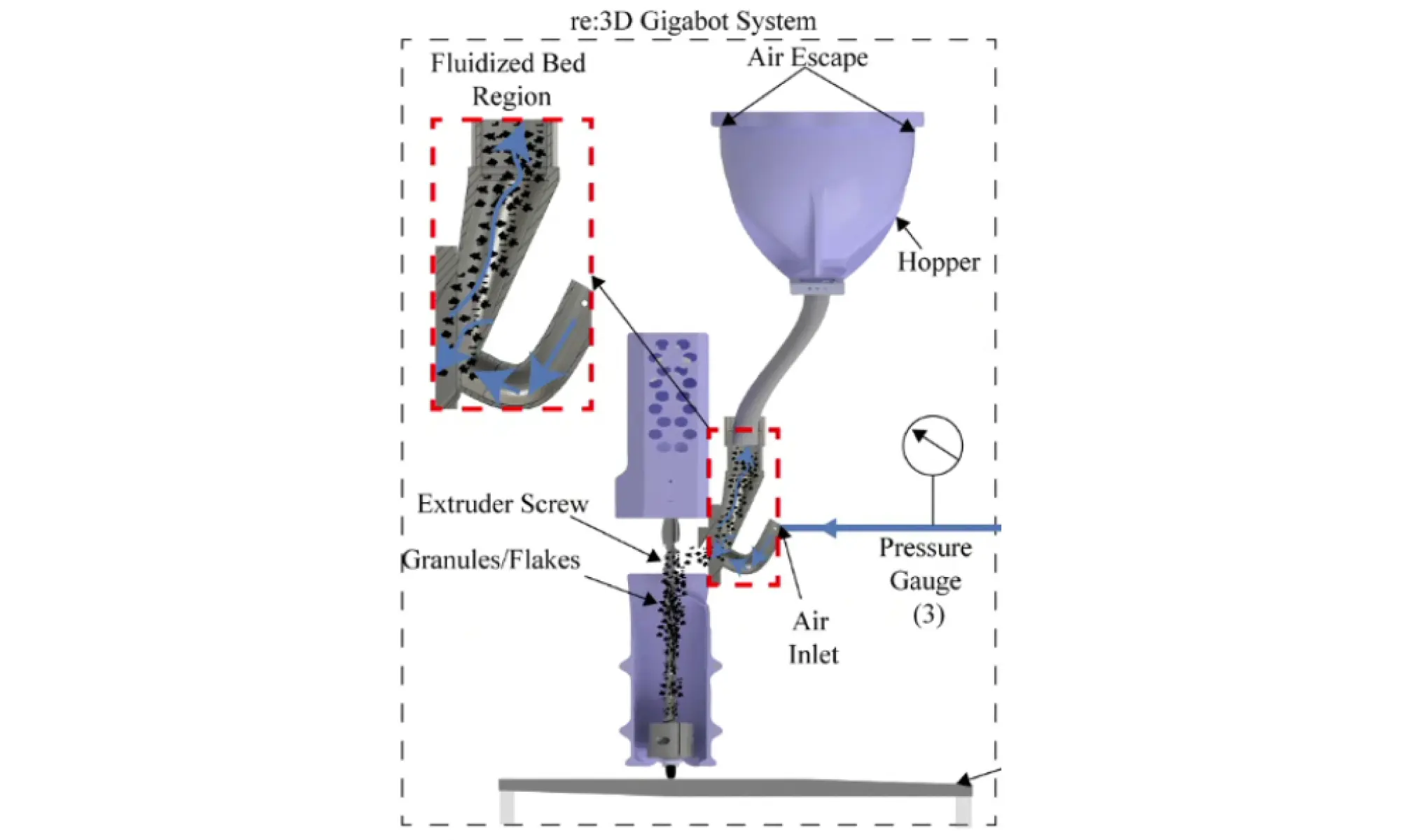
The fluidized bed system designed by Dr. Christopher Pannier’s team at the University of Michigan-Dearborn [1] sends compressed air upstream from the feed throat (Figures 7 and 8). With the right combination of air pressure and flow rate, it is possible to create an environment where solid particles behave like a fluid – a “fluidized bed”. Under this condition, flakes can flow freely through the path without building up on top of each other. Dr. Pannier’s team has tested this system to identify appropriate combinations of air pressure, air flow rate, and duty cycle that produce ideal fluidized bed conditions. However, as of today, only one material of controlled sizes (granulated rPLA, sifted 2~3mm) has been tested. To replicate similar results and identify combinations of parameters for other materials and feedstock morphologies, extensive testing is required.

Figure 7: Fluidized bed system implemented on a GBX. (Image credit: Pannier, 2023)
Figure 8. Fluidized bed system configuration. (Image credit: Pannier, 2023)

Another option to reduce bridging is simply attaching one or more motors to the feed tube, generating vibrations or impact to remove buildups. There have been previous investigations into this solution at re:3D between 2021 and 2022, but the team faced issues including vibration-induced fatigue failures in wires and the printed feed throat. Eventually, this idea was abandoned as the team started to focus on the development of the crammer, which increased the throughput of the machine considerably. The vibration motor system helped with the consistency in extrusion rate by breaking up material buildup, but had little to no effect on the extrusion throughput. The vibration motor system could potentially be a great partner for the current crammer system, as they complement each other and address separate issues. The vibration motor system is not only a simple and cheap implementation, but also does not require major modifications to existing parts.

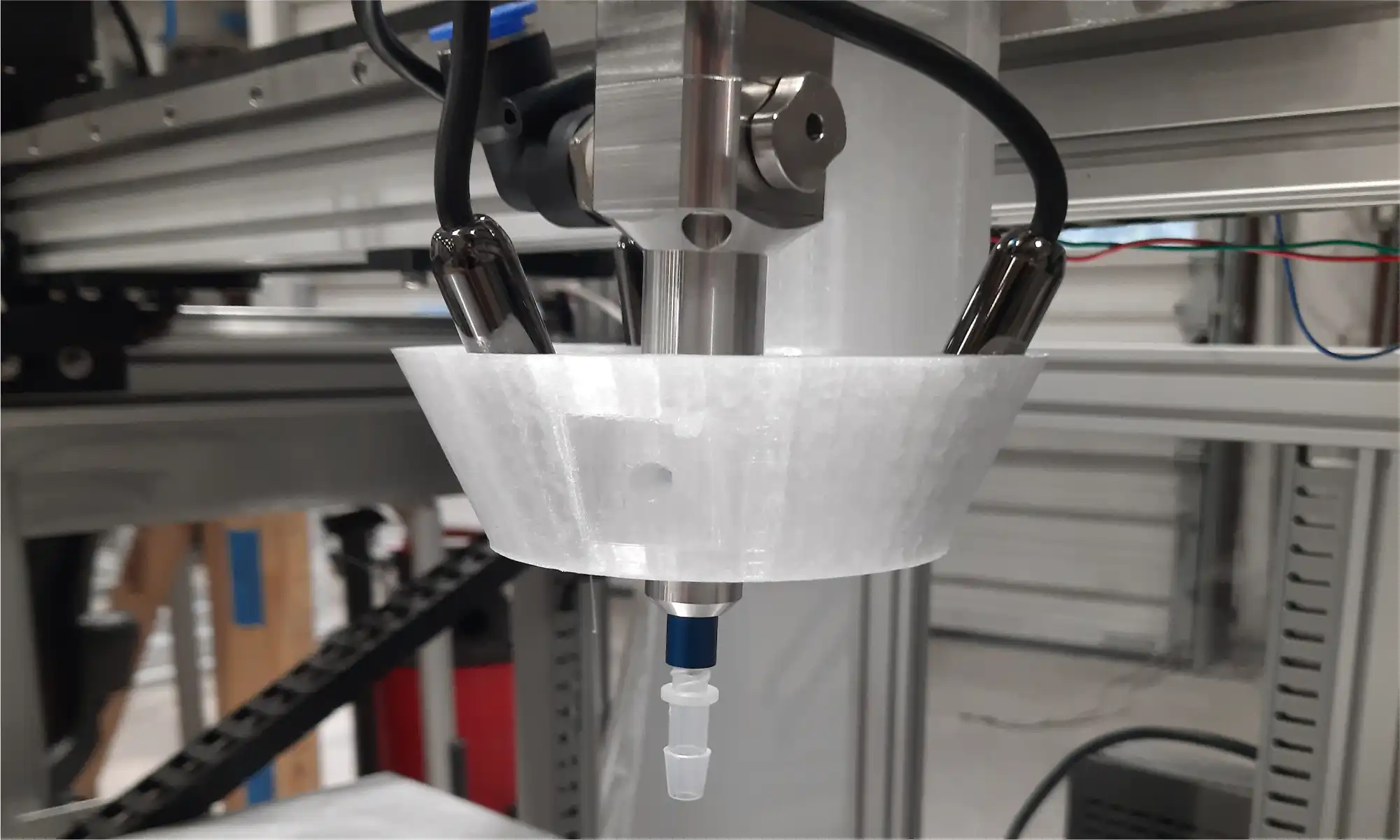
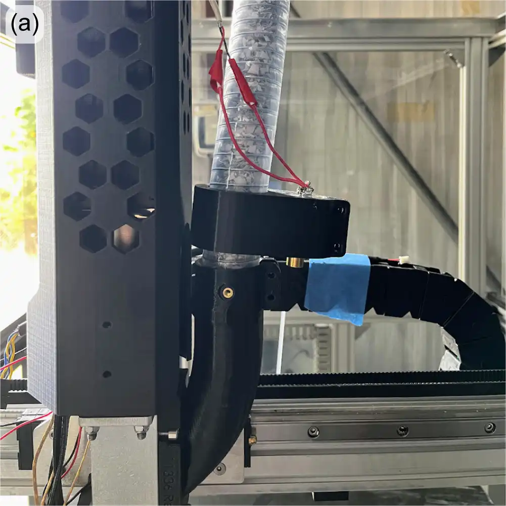
In a recent re-investigation of the vibration motor system, the motor was mounted directly onto the hose – independent from the extruder body or the crammer – such that the vibrations do not affect other systems negatively. Because constant operation of the motor may cause overheating and also accelerate vibration-induced fatigue, the motor was operated with a duty cycle using custom G-code or external python scripts. Quick testing showed promise, as even short bursts successfully broke up any material buildup along the hose. While no quantitative tests were conducted, the effect of vibrations were easily visible through the transparent feed tubing and also on the printed parts that lacked telltale signs of bridging-induced underextrusion (Figure 9). For the vibration motor system to be implemented, it will require a more robust mount design that reduces the noise (currently 50-60 dB) and secures the motor while sustaining vibrations over an extended period of printing time.

Figure 9: Vibration motor attached to GBX feedtube (a); recycled polycarbonate prints without and with vibration motor activated (b).

For now, a few minor tweaks to the ‘beta’ crammer have resulted in reliable and consistent extrusion performance for most feedstock materials and morphologies. But it’s good to have experience with additional options should the need for additional bridging mitigation arise.

Software Improvements

The software team at re:3D is incredible. Their most recent work to improve customer experience with the Gigabot and GigabotX printers includes bed mesh compensation, the new Klipper stack V0.5.0, improved print recovery, and a new web application: Helm.

Mesh Compensation Enhancements

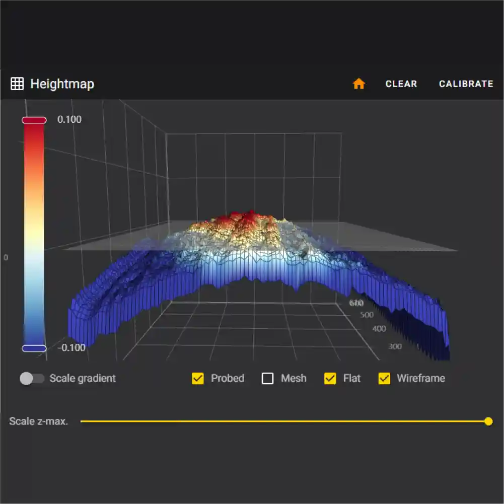
Reliable printing requires reliable, high-quality first-layers. One key factor to a successful first layer is proper bed leveling, or more properly, bed tramming. Manually leveling the large print beds on the Gigabot and GigabotX printers might take a bit of practice, but the system does remain stable – until heat is applied. When materials (especially metals) heat up, they tend to expand. Depending on the mechanical constraints on the object, its shape will change. In the case of a flat metal plate with fixed constraints as shown in Figure 10, heating a print bed can cause bowling or warping at these elevated temperatures. No matter how much you try to “level” the bed, the print nozzle will not remain a constant distance from the bed surface without active correction.

Figure 10: Depiction of thermally-induced deflection of a mechanically constrained bedplate.

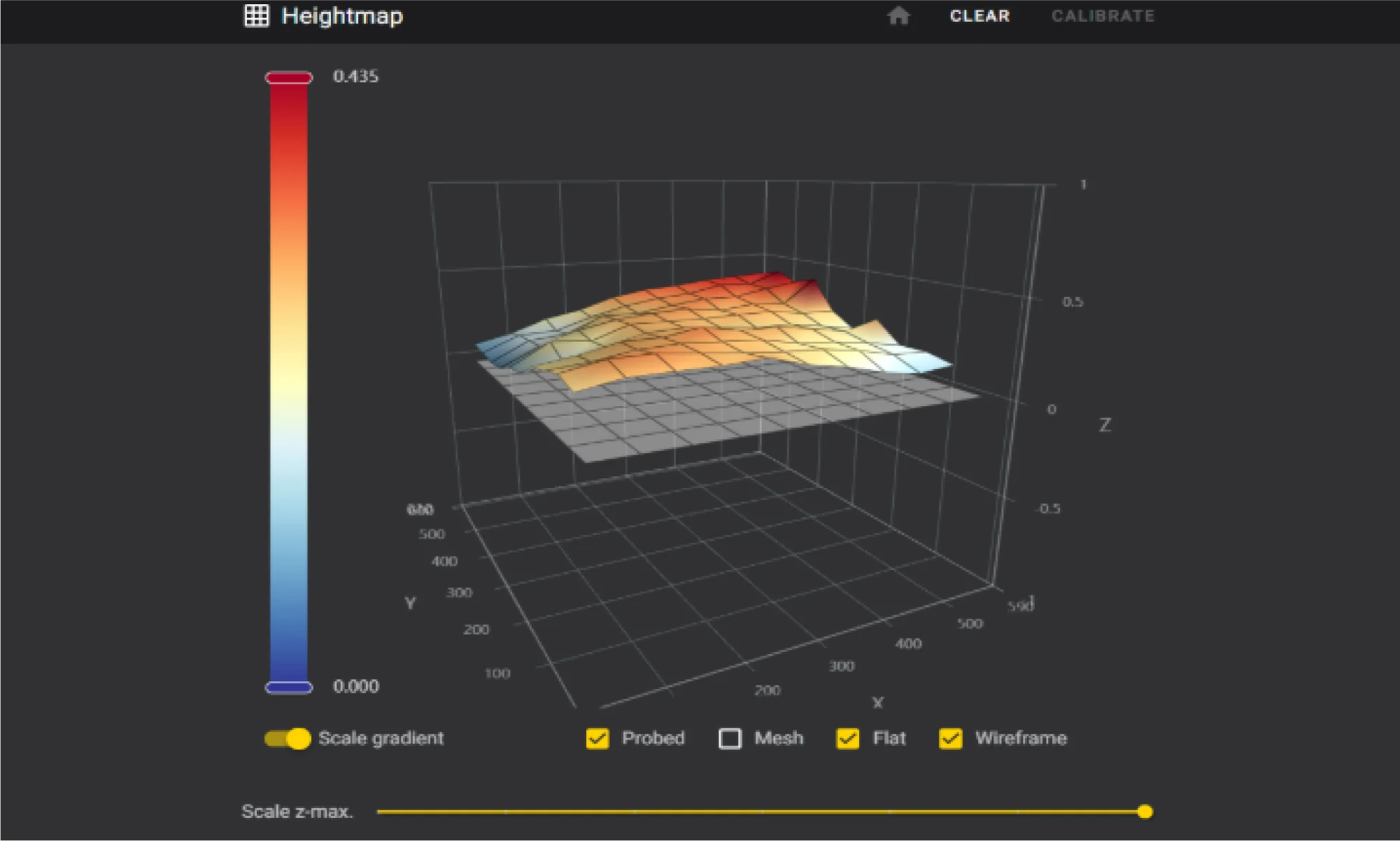
Enter “mesh compensation”. In this method, a map, or mesh, of the now-warped bed is measured with a sensor. This heightmap (Figure 11) can then be used in a mathematical algorithm to correct for changes in distance between the nozzle tip and the bed surface, and the firmware will automatically adjust the z-axis height to maintain the appropriate “height”, leading to improved first-layer adhesion, consistency and overall quality.

Figure 11: Bed heightmap generated from the eddy current sensor and bed mesh compensation software.

The team has been working hard to perfect mesh compensation to ensure it’s ready for release. An eddy current scanner was selected for its high precision, performance, and rapid data collection. Despite the clear benefits, the scanner’s reliability was a concern for users. Disconnections during a print would trigger an error and cause the print to fail, as the scanner is recognized as a main control unit (MCU), and Klipper naturally shuts down when an MCU is unresponsive or disconnected. During initial beta testing, about 33% of machines experienced these disconnections, which was consistent with in-house testing.

The software team conducted thorough investigations with the manufacturer and explored how Klipper handles MCUs – ultimately deciding to implement a feature in Klipper to declare and allow non-critical MCUs. This change prevents print stoppage if a disconnection occurs, as the scanner is not essential during an ongoing print. After this adjustment there were significant improvements in testing. This enhancement ensures that mesh compensation is not only accurate but also reliable, laying the groundwork for its upcoming release.

Klipper Stack V0.5.0

The release of Klipper stack V0.5.0 was delayed in 2024 due to the move but is now available to download from re:3D’s Github repository. This update introduces fine-tuning for machine parameters, new features, and fixes for existing issues. Currently, the process involves building the operating system, configuring dependencies, and settings, and then creating a copy of the entire OS, which is compressed into an image file for SD card deployment. This method is slow and cumbersome, requiring a near-perfect system state before imaging.

While the Klipper configurations are stored in a GitHub repository, allowing remote updates for machine configurations, system component updates are not possible remotely. V0.5.0 extends the ability to modify certain components, but system-wide modifications remain out of reach. The best approach may be a shift to variant creation of the distribution that grants total control over the OS and its dependencies. This would enable nightly builds and allow every system component to be modified remotely.

Improved Print Recovery

There has also been a lot of work improving the print recovery workflow. The current recovery tool, while useful, requires manual efforts and often results in noticeable layer artifacts. The new method, which is native to the Klipper stack, is fully autonomous and more accurate. It monitors a print in progress, constantly recording the current position of the G-code file by byte. If a stoppage occurs due to an error or other causes, the file is automatically copied and parsed to the exact last G-code line, while preserving the start G-code. This ensures that the print resumes exactly where it left off without creating a layer artifact. This new print recovery feature will significantly reduce the need for manual intervention, making the printing process smoother and more reliable.

The only caveat is that this method doesn’t cover power interruptions. To recover from a power outage, an uninterruptible power supply (UPS) would be required to send a signal to the printer’s Raspberry Pi, triggering a script when a power failure is detected.

Introducing Helm: A New Web Application for Printer Fleet Management

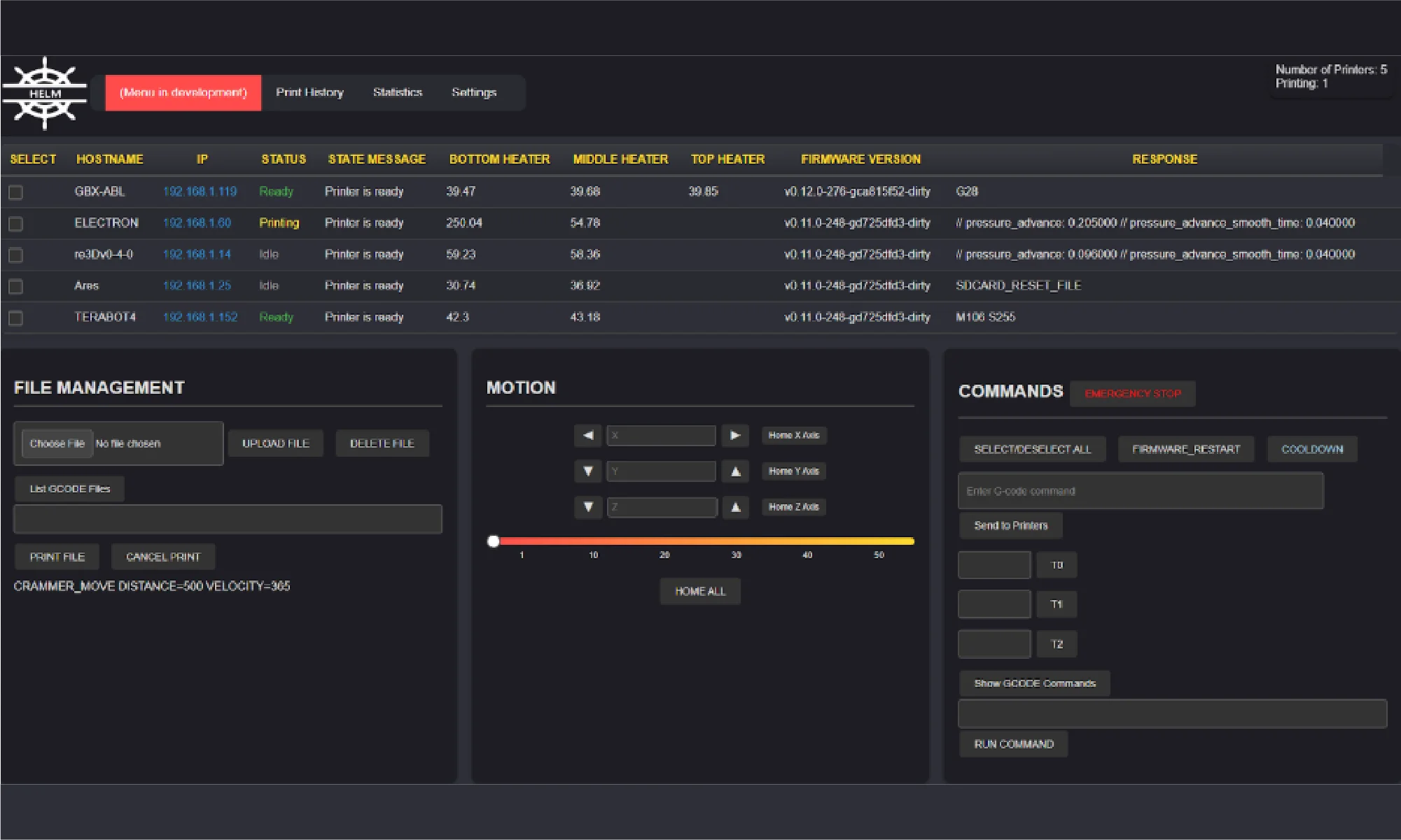
Managing multiple printers in the factory was becoming a challenge, so re:3D’s lead software engineer developed a simple script to query devices on the network and find connected printers. This script has now evolved into a full-fledged web application for printer fleet management, aptly named Helm. Helm offers many features to enhance monitoring and synchronous communication across the network.

Helm is similar to Mainsail in that it uses the Moonraker API to communicate with Klipper, but it automatically detects Klipper printers on the network and displays detailed, dynamic information on a single page (Figure 12).

Figure 12: Helm dashboard.

Here are some of Helm’s key features:

  • Server hosted on the local network for multiple clients
  • Automatic network scanning to connect to printers
  • Status monitoring
  • Display of hostname, IP address, and firmware version
  • Dynamic monitoring of status, state messages, temperatures, and command responses
  • Multi-printer selection for command execution
  • File upload/deletion
  • Start/stop prints
  • List G-code files on a particular machine
  • List commands
  • Send G-code commands
  • Set temperatures
  • Cooldown heaters
  • Firmware restart
  • Emergency stop

Helm is still a work in progress, but it’s an open-source project and open to contributions. You can try the application yourself, report problems, contribute, or follow progress here: Helm on GitHub. Helm is designed to simplify printer management and will continue to evolve with input from the community, ensuring it meets the needs of users managing multiple printers.

R&D Programs

re:3D is proud to have a robust R&D program, sponsored in part through industry and government awards and contracts. Each of these could consume its own blog post (and perhaps someday will, disclosure rules permitting). For now, here’s a brief summary of recent and ongoing programs re:3D is engaged with through the Department of Defense, NASA, the Department of Energy and the National Science Foundation.

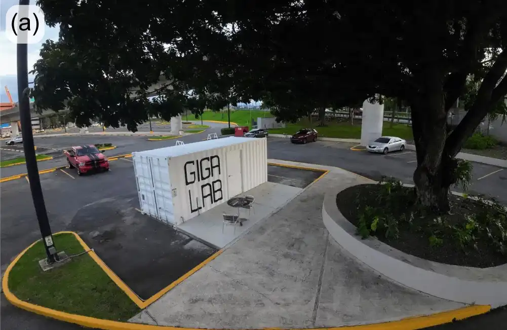
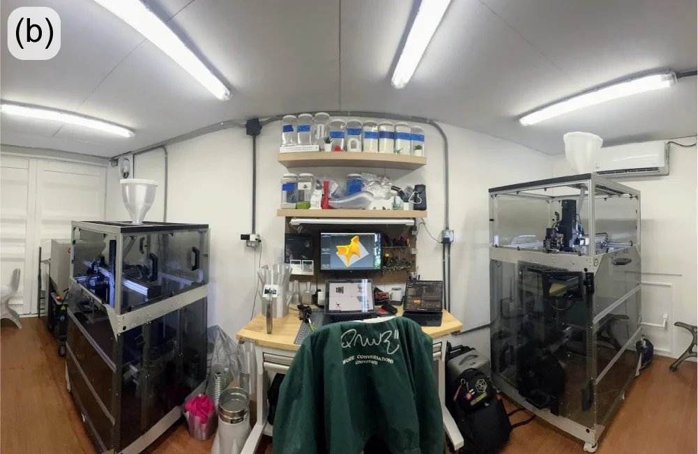
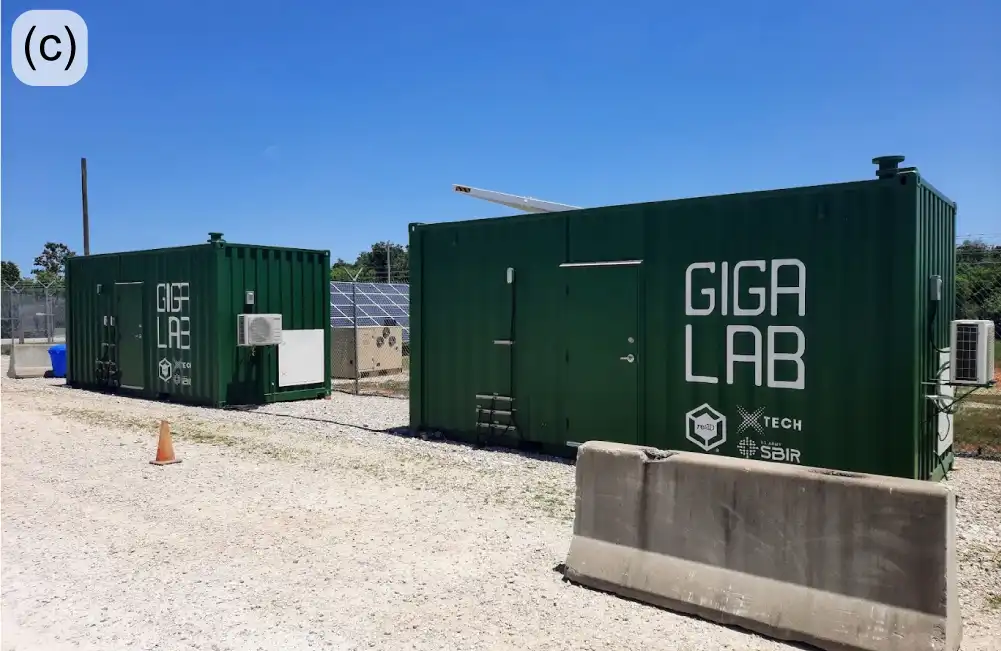
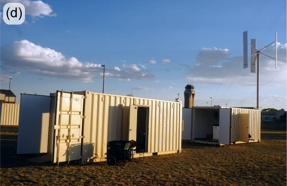
One of the visions of re:3D’s founders was to provide a means of production to people in need, who could fabricate parts from local and salvaged materials. The Gigalab is a huge step towards fulfilling that vision. Within a modified 20-ft shipping container, the Gigalab Mobile Recycling Facility can contain all of the equipment required to break down waste plastics to use as feedstock for printing functional items with a GigabotX printer. Multiple variants of Gigalabs have now been fielded at four locations: the Engine-4 coworking lab in Bayamón, Puerto Rico; an Army Corp of Engineers facility at Fort Leonard Wood, Missouri; Cannon Air Force Base in New Mexico; the Austin Habitat for Humanity ReStore location in Austin, Texas (Figure 13).

Figure 13: Gigalab at Engine-4 in Bayamón, PR (a-b); Fort Leonard Wood Gigalabs (c); Gigalabs with wind turbine power at Cannon Air Force Base (d).

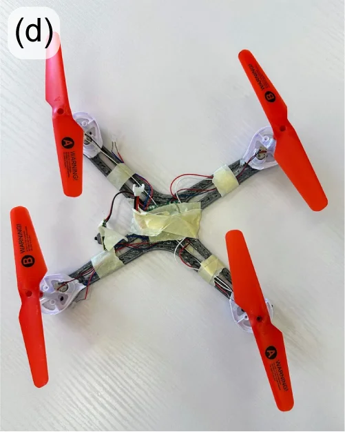
You can learn more about re:3D’s Gigalab at Engine-4 in Puerto Rico in an earlier re:3D blog post here: October 2023. Last year’s highlights from the US Army and US Air Force Gigalab projects included logistics challenges, travel to Los Angeles to install a custom energy-management system and fabricating (and flying) small drones printed from recycled drones (Figure 14).

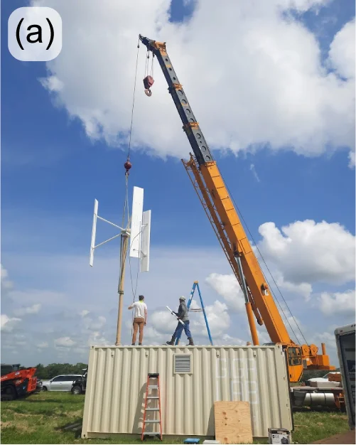
Figure 14: Installation of a wind turbine on a USAF Gigalab at re:3D’s Carmine, Texas interim test site (a); installation of a custom energy management system for the US Army Gigalabs at Wenzlau Engineering in California (b); iterations of printed “drones from drones” at Cannon Air Force Base in New Mexico (c-d).

ReCreateIt (NSF)

ReCreateIt is a multinational collaboration led by re:3D to transform waste plastic into valuable products with 3D printing and community-led design. The Gigalab located at the Austin Habitat for Humanity ReStore is a part of this program, which is funded through the National Science Foundation’s Convergence Accelerator. In order to maximize the value of “trash-to-treasure” in converting waste thermoplastics collected at the ReStore into printed goods of value, re:3D now employs a polymer scientist dedicated to this project who will investigate and optimize the processing and printing parameters to best recycle plastics via material extrusion additive manufacturing (3D printing).

Recent success in 3D printing with recycled polypropylene (PP) is evidence of the benefit of having a polymer scientist on staff. PP is the second most widely produced plastic in the world, and is commonly used for consumer items, including storage bins, which are available in large numbers for recycling at the ReStore (Figure 15(left)). However, PP is commercially recycled at a rate of less than 5% – partly due to industrial processing and economic challenges. Additionally, as with all members of the polyolefin family of polymers, it is notoriously difficult to use as a feedstock in 3D printing, even in a neat or virgin state, let alone as recycled granulate. But the perseverance and dedication of the ReCreateIt team is paying off as evidenced by the printed vase in Figure 15(right), along with many other great successes.

Figure 15: Members of re:3D’s ReCreateIt team sorting plastics at the Austin Habitat for Humanity ReStore (a); decorative vase printed from polypropylene laundry baskets and storage totes (b).

Low-SWaP Waste-to-Print System (NASA)

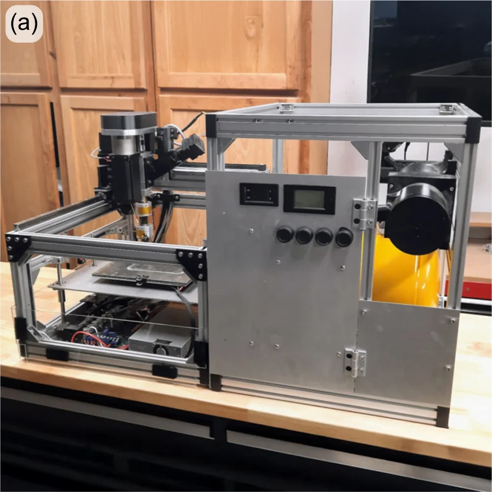
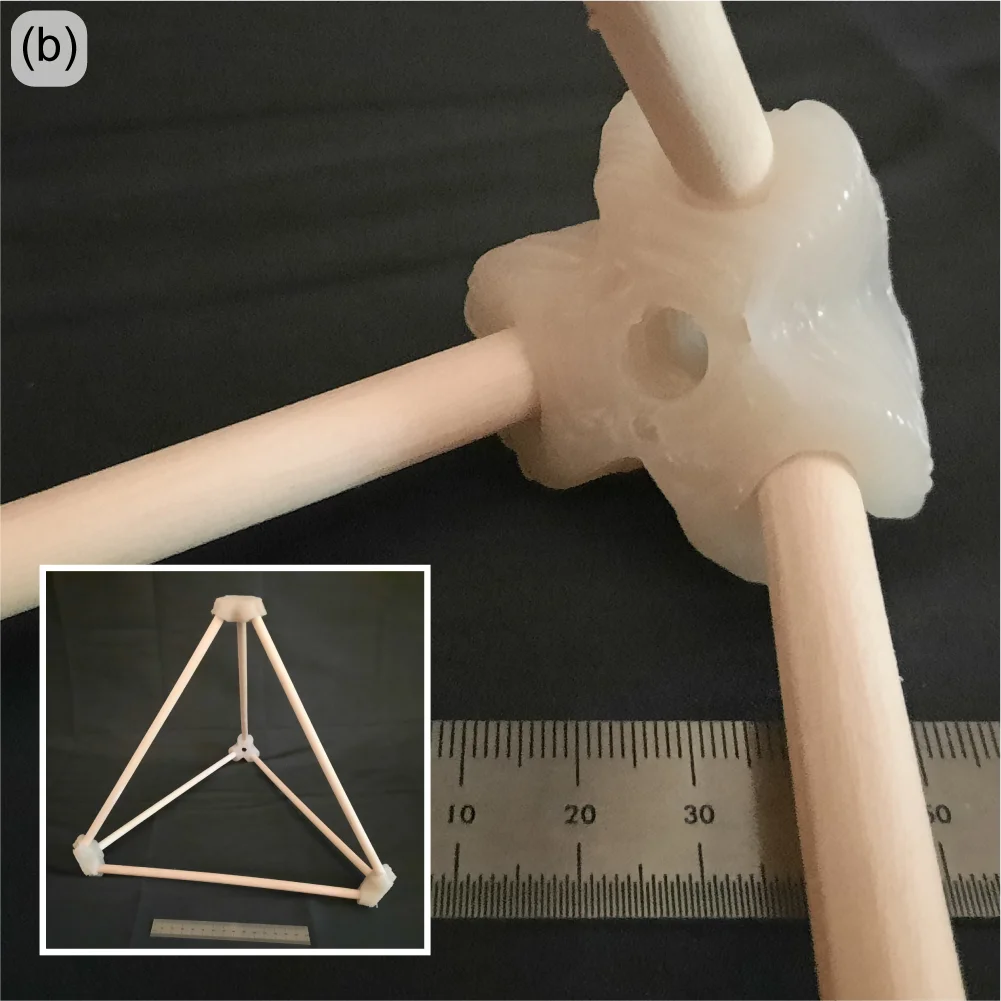
Remember the Gigalab – a converted 20-ft shipping container with the equipment to granulate plastics and print objects of use? Now imagine a similar system the size of a dorm refrigerator that uses half the power of a common space heater and is designed to work in space. This is the objective of a research contract re:3D was awarded through NASA for the Artemis Gateway program. The GigabotX has been repackaged into a low size, weight, and power (SWaP) version and integrated with a custom granulator (Figure 16(left). The system is intended to recycle packing foams which are necessary to protect payloads during liftoff, but are largely unnecessary once in space – or on the lunar or Martian surface. These foams can then be recycled for repair parts, construction materials or other items which would otherwise need to be delivered separately (at significant cost). The system isn’t ready for flight testing yet, but interim hardware demonstrations have already been performed for NASA on-site at Kennedy Space Center in Florida.

Figure 16: Low-SWaP printer and granulator system (a); tetrahedral dowel connectors printed from shipping foam (b).
“Bigger, Better, Faster” FGF (US Army)

Building on the success of one of re:3D’s R&D contract with the US Army to demonstrate printing from waste in a Gigalab, sequential funding was secured to print bigger, better and faster – using a wider range of recycled materials as feedstock. This will still be a cartesian FGF printer built on an extrusion frame, but larger in footprint than re:3D’s TerabotX (Figure 17). The extrusions are larger and stiffer, and the design is more easily scalable in the length axis to accommodate future development goals. The bed will be stationary with better access from the front and back to aid print monitoring and removal. For motion control, stepper motors are being replaced with servo motors for improved speed and torque performance, and linear screws are replacing belt drives for translation. The standard ArchiMajor control board will still be used, but a custom breakout board has been designed in-house to provide servo motor control, and the Klipper GUI interface is getting an upgrade to better reflect the operation of an FGF printer.
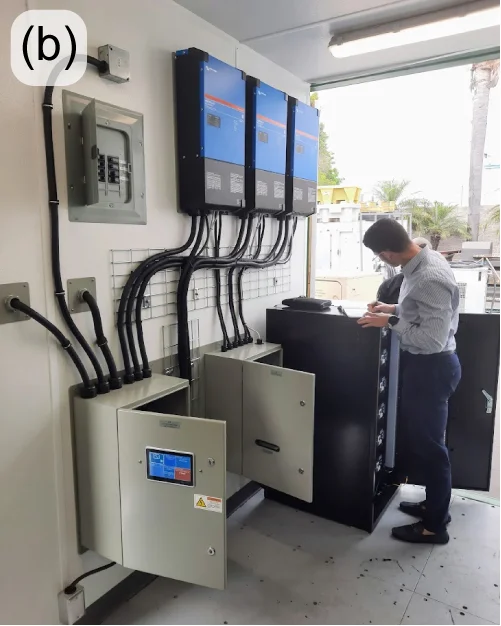
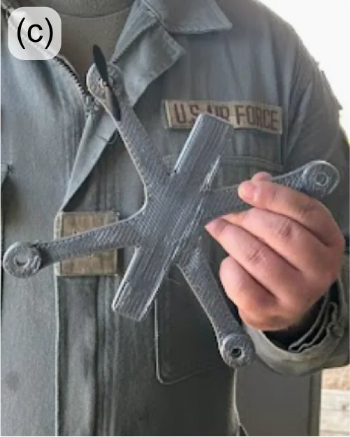
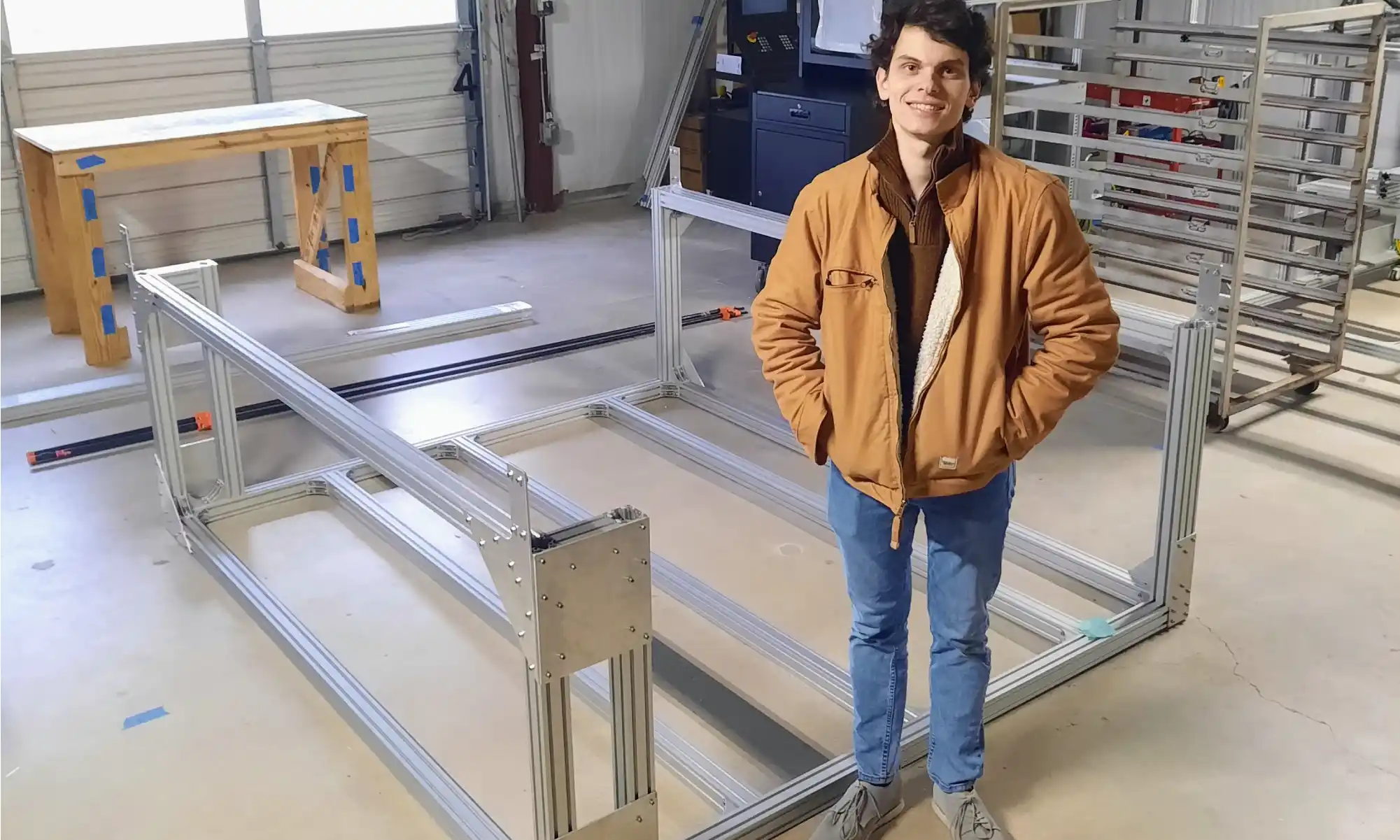
Figure 17: FGF R&D printer lower frame for the US Army. Hardware Engineer for scale.

re:3D is very pleased to collaborate with Dr. David Kazmer and his team at the University of Massachusetts Lowell to design, fabricate and optimize a new extruder with a novel screw for this project. The extruder length won’t change much from the existing GBX design, but the screw’s diameter will double and provide a very significant increase in throughput. Additional support is coming from the University of Maine’s Advanced Structures and Composites Center (ASCC). They will be leading the effort to develop recycled biocompounds – that is, feedstock materials produced from recycled polymers and wood or paper waste. This is an exciting R&D project with many possibilities for cross-development into re:3D’s portfolio of standard printers and other collaborative opportunities.

Additively Manufactured Thermal Protection Systems (NASA)

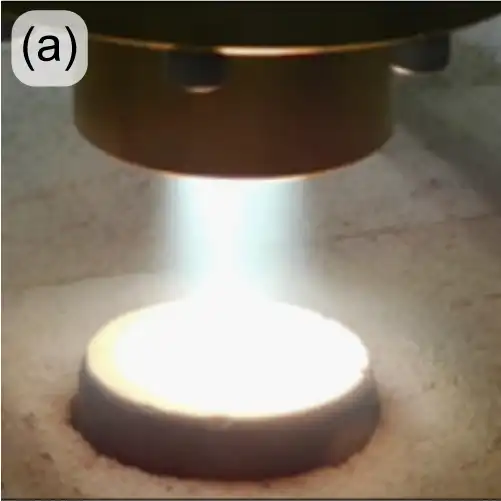
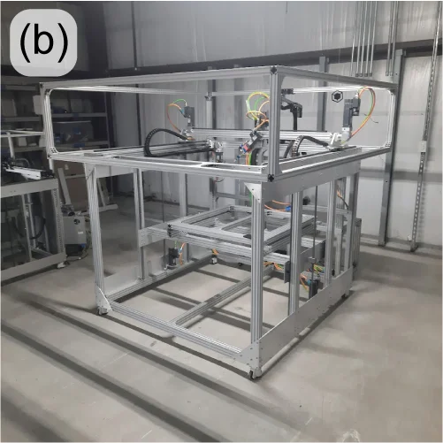
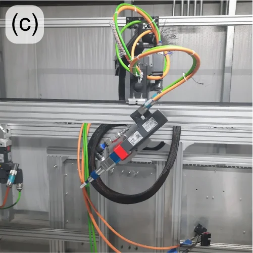
When a spacecraft enters a planet’s atmosphere, friction generates extreme heat which can damage the craft and payload (human crew or otherwise). Thermal Protection Systems (TPS) are materials designed to insulate and dissipate that heat energy – often through charring and re-radiation. Under an R&D contract with NASA / Johnson Space Center, re:3D is developing a pilot manufacturing system to print TPS materials directly onto spacecraft heatshields and other structures. Dr. Brett Compton and Dr. Damiano Bacerella (University of Tennessee – Knoxville) are developing and testing a phenolic-based foam, which when cured at elevated temperatures forms a ceramic-like TPS structure (Figure 18(a)). re:3D, in turn, is designing and building a printer to deposit the foam onto a large, non-planar aluminum dish. This requires a 5-axis printer with advanced controls (Figure 18(b-c)). re:3D is collaborating with Siemens/CATCH on the industrial motion control system, and with Addiguru for deposition monitoring.

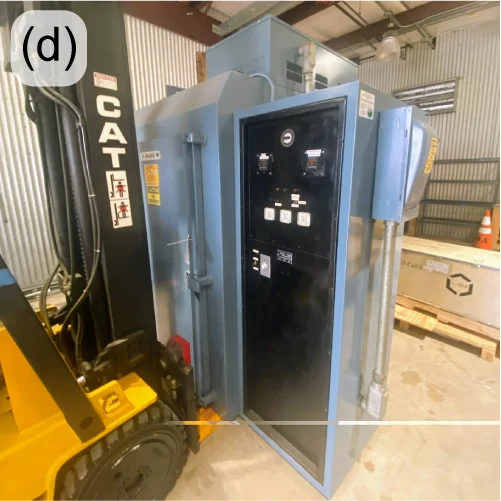
Besides the unique opportunity to work on #supercoolNASAstuff, this project is giving re:3D additional experience with new industrial control systems, 5-axis tool-path planning and printing thermoset materials. Thermosets differ from thermoplastics in that they start out in some fluid form and require heat to harden (rather than just melting and recooling, as do thermoplastics). This gained experience with thermosets will allow re:3D to provide new opportunities to work with customers on a wider range of material extrusion projects. The deposition monitoring system being spearheaded by Addiguru may also be modified for future inclusion in re:3D’s commercial products. Finally, this provided the R&D team a reason to purchase a large truck oven (Figure 18(d)) for curing the TPS foam after it is deposited onto the aluminum dish. It might also be for a dual-use on Pizza Fridays.

Figure 18: High-energy testing of TPS foam (a); AMTPS printer frame (b); ViscoTec deposition head on multi-axis mount (c); Blue-M truck oven (d).

Water Bottle Granulation (DOE)

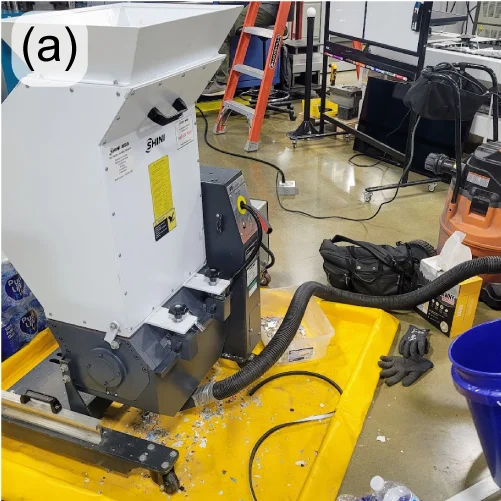
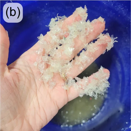
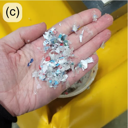
Through a Cooperative Research and Development Agreement (CRADA) with Oak Ridge National Laboratory in Tennessee, re:3D is partnering with Oak Ridge’s Manufacturing Demonstration Facility (MDF) to develop a low-cost and accessible granulator that can break down water bottles into appropriate flake (Figure 19(left)), even if they are still full of water. Collaborators at ORNL/MDF are also investigating the best ways to separate the different polymer components of the granulated water bottles (Figure 19(center, right)) so they don’t have to be pre-processed to remove the lids, safety rings and labels – often done manually in small-scale operations. Phase II of the project was approved in 2024.
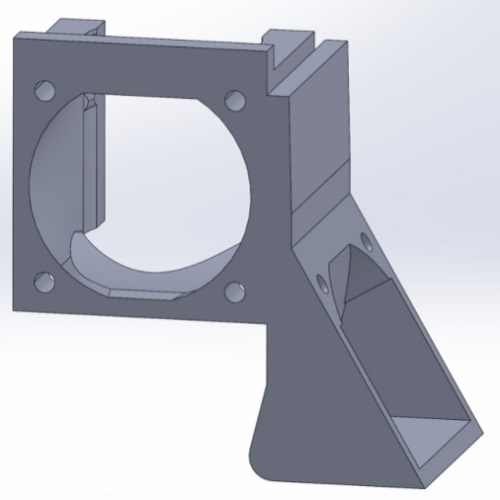
Figure 19: Plastics granulator with modified controls to safely process wet water bottles (a); separated water bottle flake: PET bottle portion (b) and PP/PE lid and label portion (c).

This was a long post. But there was a lot to cover from last year, and it’s been awhile since an engineering update was posted to the blog. Thanks for sticking with it, and stay tuned for more (frequent) updates.

As always… Happy Printing!

References

[1] 3DBenchy.com
[2] Al Nabhani, D.; Kassab, A.; Habbal, O.; Mohanty, P.; Ayoub, G.; Pannier, C. Benchmarking the Tensile Properties of Polylactic Acid (PLA) Recycled Through Fused Granule Fabrication Additive Manufacturing. In Proceedings of the Solid Freeform Fabrication Symposium, Austin, TX, USA, 14–16 August 2023. https://doi.org/10.26153/tsw/50919

Patrick Ferrell

Senior Engineer

Engineering Update – April 2024

It’s been a while since we’ve shared the progress being made by re:3D’s engineering team – June 2023, to be precise. But with the move of our headquarters from Houston to Austin (Texas) underway, it seems like a good time to take stock of where we are and where we’re going in the figurative sense as well.
The Gigabot FFF (Filament) Platform

Filament grinding diagram

re:3D took an intense look at reports of “filament grinding” submitted by our Gigabot user community, taking input from all the spheres within our company. It turns out that “filament grinding” means different things to different people, so our first step was to agree on a common lexicon and definition. We landed on a concise problem statement: “Customers experience poor extrusion performance due to the extruder gear removing material from the filament, “ which captures multiple causes and failure modes or symptoms. The engineering team evaluated, modeled and tested printer components all along the filament path – beginning at the spindle holding the filament spool down to the exit of the extruder nozzle. While recognizing that every user can encounter unique challenges and edge cases, this exercise ranked potential root causes and recommended optimizations in printer slicing parameters and specific improvements in the extruder manufacturing process. We expect these internal improvements and updated slicer profiles to improve overall reliability and print quality.

During check-ins with our customers, we also receive a lot of interest in “automatic bed leveling” – another phrase that can have multiple meanings. We have incorporated an inductive sensor into the Gigabot’s extruder assembly and integrated the necessary software to allow the sensor to quickly map variations in the print bed surface and compensate the z-axis in real time to maintain a uniform nozzle-to-bed distance. This “bed mesh compensation” approach can yield exceptional first-layer results, even on a warped or non-trammed print bed. Our software team is working with the sensor manufacturer to improve the interface and provide a quality user-experience within the Klipper environment. After we finish mesh compensation development on our R&D and internal production printers, we’ll invite the user community to apply to beta test this new feature.

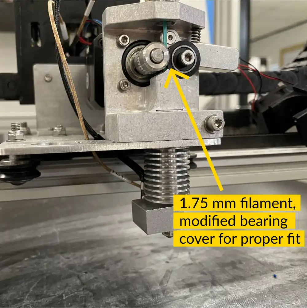
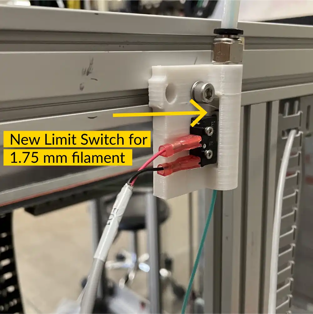
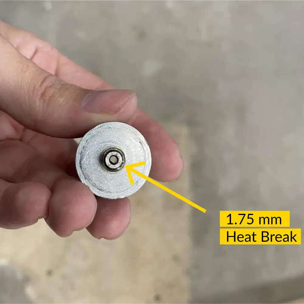
Our user community has also expressed a desire for a 1.75mm diameter filament option for re:3D’s Gigabot printers (where our extruders are designed for 2.85mm diameter filament.) In response, we have designed and are testing a conversion assembly to accommodate the smaller filament. The design has been tested for over 300 hours using a variety of filament materials – including flexible filament. It will soon be released as a kit which can be installed by users in the field.

The GigabotX FGF Platform

Crammer on top of a concrete surface

Specific to re:3D’s FGF platforms, the engineering team has focused on improving the performance and reliability of the extruder assembly. The standard ⅝” compression screw has remained unchanged, but the active feeding mechanism (i.e., the ‘crammer’) is getting a full overhaul. Feedstock with poor flowability such as coarse or lightweight plastic regrind and some TPU/TPE resin pellets can have difficulty flowing from the hopper to the extruder via gravity. The crammer provides an auxiliary auger to force these materials into the extruder body. The new design allows for higher and more uniform throughput, and increases reliability by using a stainless steel auger and machined components. Photos and design details, as well as a link to apply to be a beta-tester, are posted here on our User Forum.

In conjunction with the new crammer design, we have been testing an “autoloading” system to supply feedstock from a floor-mounted hopper rather than our normal top-mounted hopper. This system uses compressed air to drive an eductor which pulls and pushes the feedstock into the printer’s extruder via flexible tubing. A detection unit is mounted at the extruder which detects when the feedstock needs replenishing and triggers the compressed air to transport additional flake or pellets. The autoloader is currently being tested on a TerabotX which will be delivered in one of our Gigalab projects. It can operate as a stand-alone system or interface with the Archimajor control board and Klipper firmware to automatically pause printing if a feedstock delivery error is detected.

Coupler spinning

Other efforts underway include designing a more robust coupling mechanism between the extruder motor and the extrusion screw, installing a fourth heating zone to better control the nozzle/die temperature, and a deep-dive investigation into part-cooling for the GigabotX.

Software/Firmware

We are pleased to announce the upcoming release of Klipper Stack v0.5.0. This update represents a significant commitment to enhancing backend operations and ensuring our technology aligns with the latest developments within the Klipper community. Our focus on these upgrades positions us well for the introduction of innovative features in the future.

In pursuit of refining the user experience, we have streamlined the machinery setup process, enabling more rapid and efficient configurations. Enhancements include the introduction of prompt menus for various commands and adjustments to the location and visibility of the emergency stop button to reduce the risk of accidental activation. Furthermore, we have addressed and fixed specific issues such as the omission of certain characters and the disappearance of the virtual keyboard on touch-screen devices after each keystroke, ensuring a smoother and more reliable interaction.

This version also introduces a suite of new features and configuration adjustments. Highlights include the introduction of the ‘exclude objects’ module, which offers the flexibility to remove specific models from multi-model prints directly from the gcode mid-print. The ‘gcode arcs’ module expands movement options beyond the basic G1 move, incorporating G2 and G3 moves for enhanced precision. Furthermore, we have eliminated the homing sequence prior to resuming prints, addressing the issue of potential layer shifts on models.

These enhancements and fixes are part of our ongoing commitment to providing a robust and user-friendly platform, setting a solid foundation for future developments. The update is scheduled to release within a month.

Internal Processes

Internally, the engineering team is implementing processes reflecting re:3D’s ethos of being responsive and transparent to our community. Our engineering change and design processes are maturing to better engage internal and external stakeholders from the beginning of problem identification and requirements definition through operational release and ongoing support. These changes will help focus our resources on those efforts which will have the greatest impact on customer success and map the work against product roadmaps which have been developed to guide the engineering team over the next 12-18 months and beyond. And as an open-source hardware company and proponents of open science, we will be increasing our efforts to share as much of our learnings with the additive community as possible. This includes making our material testing protocols more robust and aligned with industry best practices and hosting an international, monthly FGF Users Group virtual meetup open to anyone interested in printing with pellets or flake.

And More…

Other activities have included improving the printers’ electrical systems and enclosure design. The team also continues to optimize printer software profiles and investigate additional slicing programs available for filament and pellet printing. Finally, additional variants of re:3D’s Gigalab will be presently fielded for evaluations – demonstrating that it is possible to turn waste plastic into usable parts at the point of need through additive manufacturing.

Look for release schedules and more details on all of these engineering initiatives in the coming months. We’ll be sharing via our mailing list, through blog posts and on the re:3D Community Forum

Stay tuned, and Happy Printing!

Patrick Ferrell

Senior Engineer

re:3D’s HQ is Moving to Austin TX!

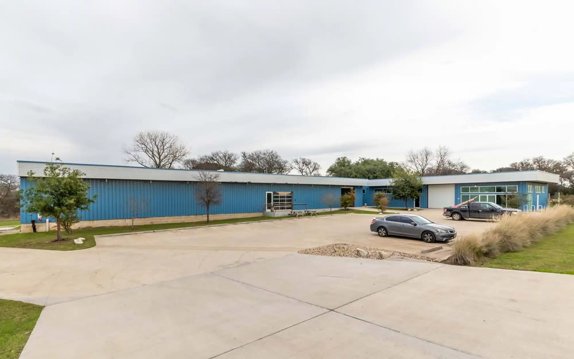
re:3D is proud to announce that we bought our own headquarters space in Austin. We will use the space to scale, grow our ability to experiment with Gigalabs in a large outdoor space, and expand our networks in Texas!

The new facility is located in East Austin, known for being a mecca that actively convenes creatives & organizations committed to social impact. This location also allows re:3D to scale locally with University of Texas and Austin Community College initiatives focused on additive manufacturing, while increasing our global presence.

We’re still working out the details, but welcome your feedback at info@re3d.org as we are committed to ensuring a seamless transition.

Below are some FAQs our team has assembled, and will be updated weekly based on your inputs.

You can witness the final move out logistics live on Wednesday May 29th from 10am-7pm. The Houston team would love to high five any visitors as we share memories and plans for the future! More information is located on our Eventbrite here. 

re:3D’s new headquarters is located at 1201 Old Bastrop Highway, Austin Texas 78742 (formally the High Sign Brewery). The building can be accessed just off of the frontage road near the 183 and 71 intersection, so if you are looking for something to do before your next flight from the Austin airport, we would love to see you! 

Our current Houston headquarters’ and Austin Office lease end May 31, 2024. For this reason we are trying to batch equipment and inventory moves each week to minimize disruptions to our operations. All headquarter operations will be established in Austin beginning June 1 2024.

re:3D has maintained a presence in parallel with Houston since 2013. We are indebted to the Clear Lake community for supporting our founding but are struggling to scale & maintain insurance for manufacturing operations in a hurricane vulnerable area. As Austin offers more opportunities for recruitment, reduced overhead, and active support from local organizations that support our social mission, we decided to move our operations, while still maintaining a footprint in Houston.

Both Charlotte, who is a Co-PI for our NSF Covergence grant, and Patrick who leads our Army Gigalabs grant as well as two NASA awards will remain in Houston. Where they will be working from is yet to be determined, and we welcome your suggestions!

While some of the Houston crew is moving to Austin (so far- Cheyena, Justin, Will, Mitchell, Jordan, and Annabelle), several teammates will be transitioning to their next adventure and welcome suggestions/introductions on where they should be applying!

Orders are being accepted, however there may be delays in for orders placed in May when we transition from Houston to Austin. For this reason, we recommend stocking up on parts prior to April 30th:) 

Tours in Houston and Austin can be arranged by emailing discover@re3d.org.

Email info@re3d.org and we will do our best to transparently reply within 24 hours! 

New Year, New Printers! Meet Gigabot 4, Terabot 4, GigabotX 2 & TerabotX 2

A green plated circuit board with many electrical components.
Left To Right: Gigabot 4 with Enclosure, Gigabot 4 XLT, Terabot 4, Exabot, TerabotX 2, GigabotX 2 XLT, GigabotX 2 with Enclosure

Introducing the Next Evolution of re:3D 3D Printers Featuring Klipper Firmware and ArchiMajor Control Boards

When deciding what changes to make on the next version of your Gigabot and Terabot 3D printers, your needs came first. The Gigabot family of customers has always inspired us to push this technology forward because it’s what you do with it that motivates us. Whether you’re teaching the next generation of change makers or innovating in advanced manufacturing, your feedback determines where we put our R&D focus.

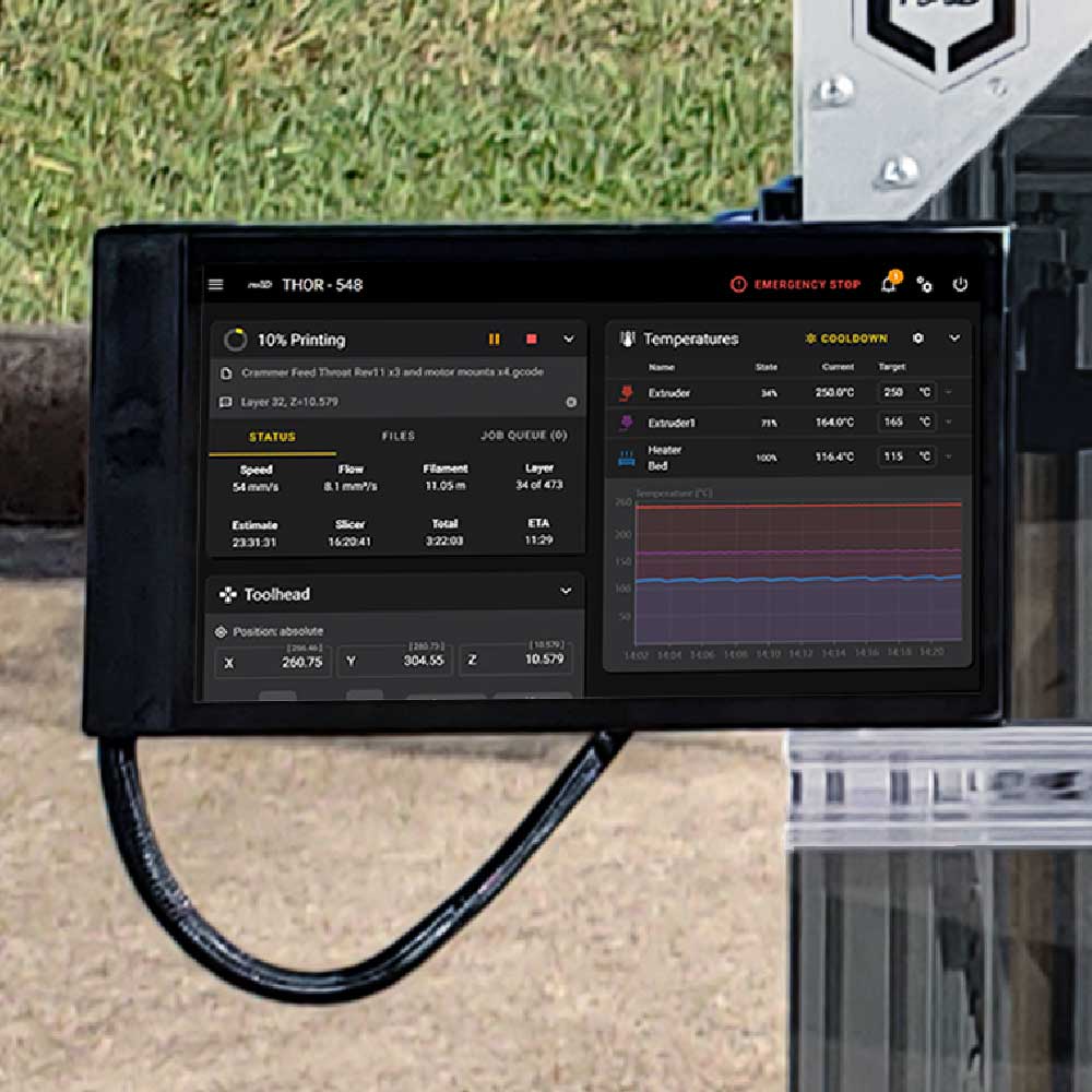
The biggest visual change you’ll see on all versions of re:3D 3D printers is the front mounted 10” full color LCD touchscreen. The touchscreen includes temperature, and motion controls, temperature history graph and preset macros. The menu options add file management, gcode editing, command line input, and print history analytics and tracking. Also included is a webcam viewer for remote monitoring and an integrated USB port for loading gcode files directly on to your printer.

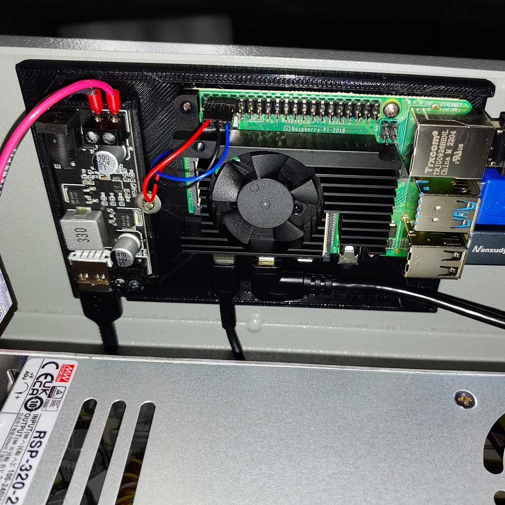
This touchscreen software is just one component of our new Klipper open-source software stack. We’ve transitioned from Marlin firmware to Klipper because it enables high precision stepper movement, smooth pressure advance and input shaping, and also an API server that enables opportunity for custom development. The Klipper web application runs the touchscreen from a Raspberry Pi and enables you to access the printer from your local network on desktop or mobile browsers with all the same control options you’re able to perform directly at the printer.

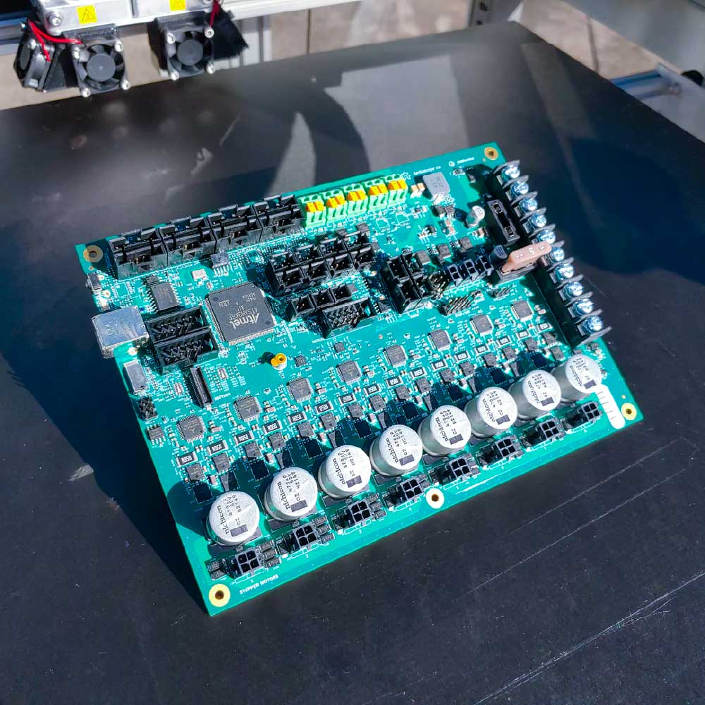
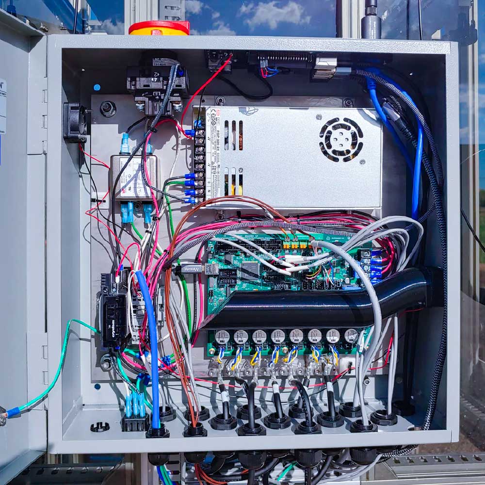
In order to successfully integrate this exciting new software stack, we’ve overhauled our electrical system starting with the control board. We partnered with US based manufacturer Ultimachine to design a custom 32bit ArchiMajor control board for your Gigabot. The advanced board features eight integrated stepper motor drivers, three heater outputs, five thermocouple inputs, four controllable fans and eight endstops. These provide flexibility to extend the functionality of your Gigabot, for example, adding an additional thermocouple or part cooling which is under development at re:3D. The new control board and the Raspberry Pi are now inside a 16” electrical enclosure with an integrated power switch, power filter and more durable flex rated cabling. Not only does this board increase your 3D printer’s processing power, but it allows us to better control our supply chain and electronics quality with a strong US manufacturer as our partner.

View the press release about this partnership.

Platform-Wide Features

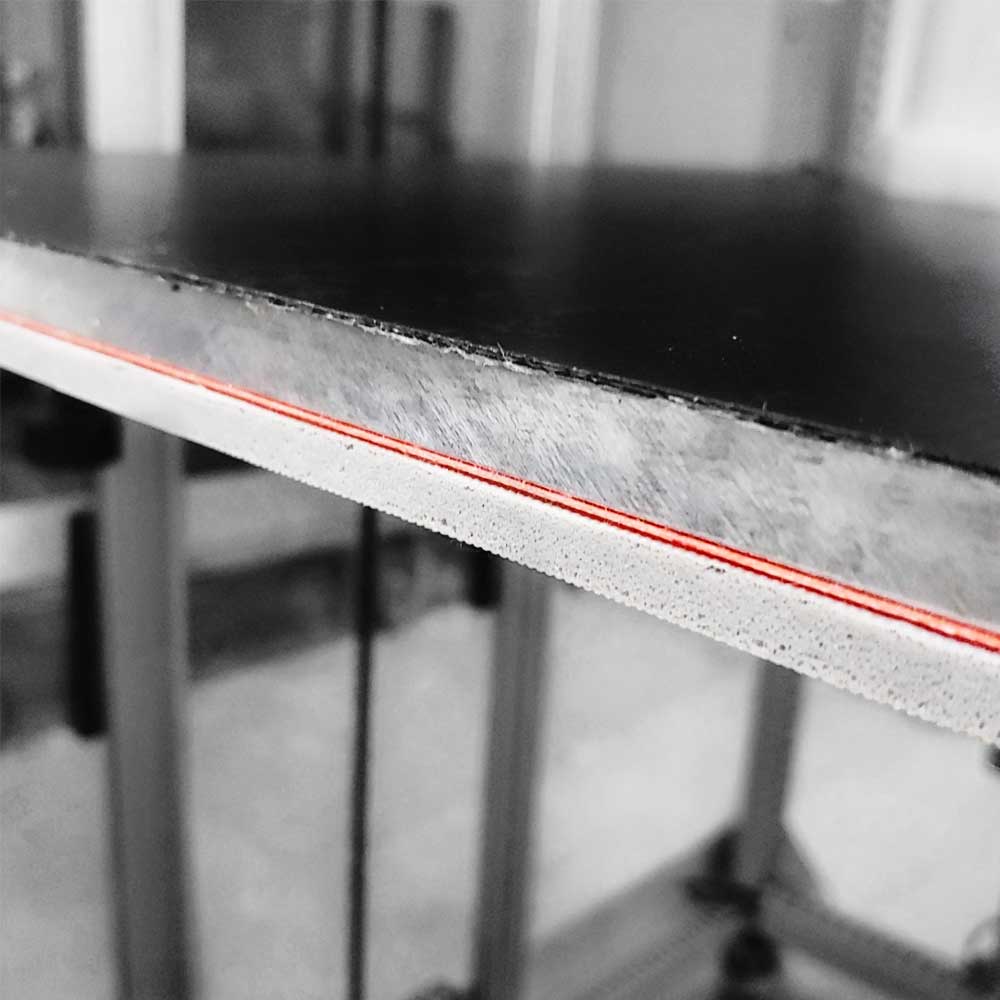
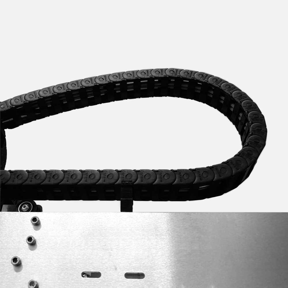
Stress tested in the re:3D factory, the new tube-style thermocouple is a more durable, consistent and accurate temperature reader for your Gigabot. We’ve added this improvement with a ½” thick aluminum bed plate, that is precision-blanchard ground flat and parallel to less than 0.005”. The bed is heated by a full-size silicone rubber heating pad, which allows the printing of high-temperature industrial materials. A robust cable carrier and cables rated for 1 million cycles of flexing protects all moving wires. Additionally, all unenclosed printers come standard with full side panels to protect electronics and cabling

FFF Filament 3D Printer Features

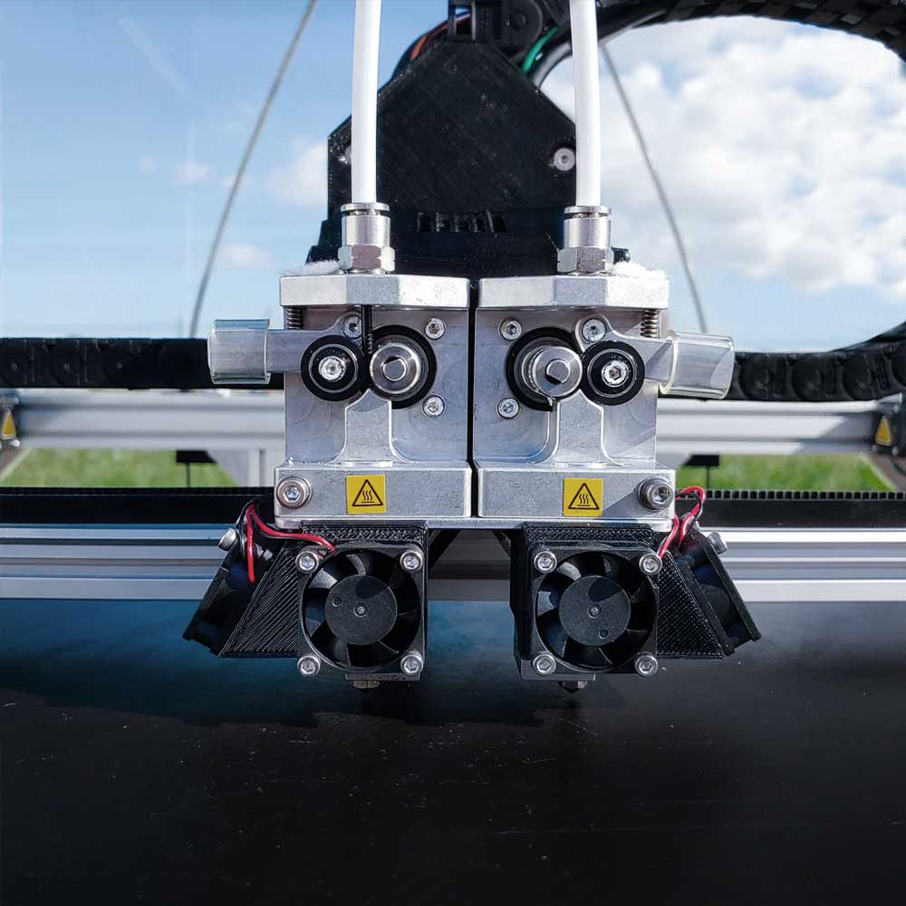
In the transition from Gigabot 3+ to Gigabot 4 we’ve pushed out some changes early as technology improvements have increased reliability and longevity for your printer. Many of these updates center around the extrusion system: The all metal extruder body, 20 Series Hot Ends for 0.8 nozzles and Terabot 4, tube style thermocouples and heater cartridges are all standard, combining to make the most robust, industrial extruder system ever on your Gigabot.

To keep Gigabot affordable you may still purchase a regular 600 mm cubed Gigabot 4 as a kit which ships in flatpack boxes, and the full enclosure is an optional add-on for pre-built Gigabot 4 and Gigabot 4 XLT sized 3D printers. Terabot 4, as before, comes with the enclosure standard. One change we’ve integrated as standard is the side panels on your Gigabot cover the full side on the left and right to provide better protection for the motors and electronic components.

As with the changes we made during Gigabot 3+’s lifespan, This is just the beginning. Gigabot 4 will continue to iterate and grow and change to meet your needs as the technology evolves. Plans are already in the works for a filament dry box, bed probing and even more robust build plate and frame improvements. Stay tuned!

FGF Pellet and Granule 3D Printer Features

Since releasing the beta version of Gigabot X in 2018, re:3D invested significant R&D resources from community support to produce a more agile, advanced and capable fused granular fabrication 3D printer.

GigabotX 2 features a feeding and extrusion system precision engineered for processing pelletized and granular thermoplastics. Material is manually fed into the 24 hour capacity hopper which rides on an independent hopper gantry system, to allow a full and smooth range of motion and consistent feeding into the extruder.

Print material flows from the hopper into the extruder via either the gravity fed feed throat or the optional active feeding system, or crammer, which includes a motorized auger that pushes material into the extruder with a user controllable feed rate.

The GigabotX 2 extruder is powered by a 425 ozf*in NEMA 23 motor with planetary gear box to provide increased torque for flowing materials. The extruder is a solid steel ⅝” screw with 16:1 L/D ratio designed with our partners specifically for consistent throughput for thermoplastics. Three independently controllable heaters are mounted on the extruder barrel allowing for extrusion temperatures up to 270°C. Interchangeable nozzles between 0.4mm and 2.85mm in diameter can be used to control resolution and extrusion width.

GigabotX 2 is the culmination of our mission to enable more users to 3D print directly from novel and waste plastics, but we’re not stopping here. Research is currently underway to integrate a granulator, dryer and automatic feeding system with GigabotX 2 to make machine operation even more efficient and user friendly and enable anyone anywhere any time to be the problem solvers for their community.

Charlotte craff

Blog Post Author

re:3D installing Terabot and Terabot X at the Autodesk Technology Center in Boston, MA

FOR IMMEDIATE RELEASE

re:3D installing Terabot and Terabot X at the Autodesk Technology Center in Boston, MA

Boston, MA – re:3D, Inc. is delivering large-format filament, pellet and granule based 3D printing to the Autodesk Technology Center in Boston. A Texas and Puerto Rico based manufacturer, re:3D’s printers are beta units of Terabot 4, a filament extrusion 3D printer with a build volume of 915 x 915 x 1000mm (36” x 36”x 39.5”) and Terabot X 2, a pellet and granule extrusion 3D printer with a build volume of 892 x 908 x 830mm (35” x 35.75” x 32.75”). The 3D printers are available for residents of the Autodesk Technology Centers Outsight Network for large format 3D printing using both virgin and recycled or reground thermoplastics. Visitors to the Technology Center can view the Terabot 4 in action now after a successful installation over the last week. The Terabot X 2 installation is forthcoming.

As part of Autodesk Research, the Technology Centers catalyze new possibilities for making through the power of connection. They bring together a global network of innovation leaders, data-enabled fabrication workshops, curated experiences, and forward-thinking ideas to empower innovators in achieving the new possible, together.

The Outsight Network is Autodesk Research’s global innovation network. It includes resident teams from industry, academic, and entrepreneurial sectors who are passionate about accelerating and researching design and make processes. Teams in the network are connected with industry experts, the diverse and vibrant Technology Centers community, resources, and if applicable, have access to advanced fabrication machinery and training.

“We are thrilled to share this technology with Autodesk and its partners at the Boston Technology Center,” says re:3D Co-founder and Catalyst, Samantha Snabes. “Enabling 3D printing from waste plastics at scale has the capacity to make real-world impact and empower local communities. We’re excited the cutting-edge designers at Autodesk Technology Centers will be researching and innovating using re:3D 3D printers, putting sustainable 3D printing to great use.”

To learn more about how Terabot and all the 3D printers in re:3D’s portfolio are built, re:3D is offering live, monthly virtual tours of its Houston, TX factory. The next opportunity is Monday, September 19, at 10:00am CT. Attendees can register at the following link: https://www.eventbrite.com/e/3d-printer-factory-tour-virtual-edition-tickets-123094640383

About re:3D
re:3D, Inc. consists of a group of explorers committed to decimating the cost & scale barriers to industrial 3D printing. Having pioneered the world’s first and most affordable, human-scale industrial 3D printer, re:3D likewise is creating large scale, affordable 3D printers printing from pellets, regrind, and flake plastic waste. Beyond creating 3D printers for customers in over 50 countries, re:3D offers 3D printing contract services, consulting, design and education services. For more information on re:3D, visit www.re3d.org.

About Autodesk
Autodesk is changing how the world is designed and made. Our technology spans architecture, engineering, construction, product design, manufacturing, media and entertainment, empowering innovators everywhere to solve challenges big and small. From greener buildings to smarter products to more mesmerizing blockbusters, Autodesk software helps our customers to design and make a better world for all. For more information visit autodesk.com or follow @autodesk.

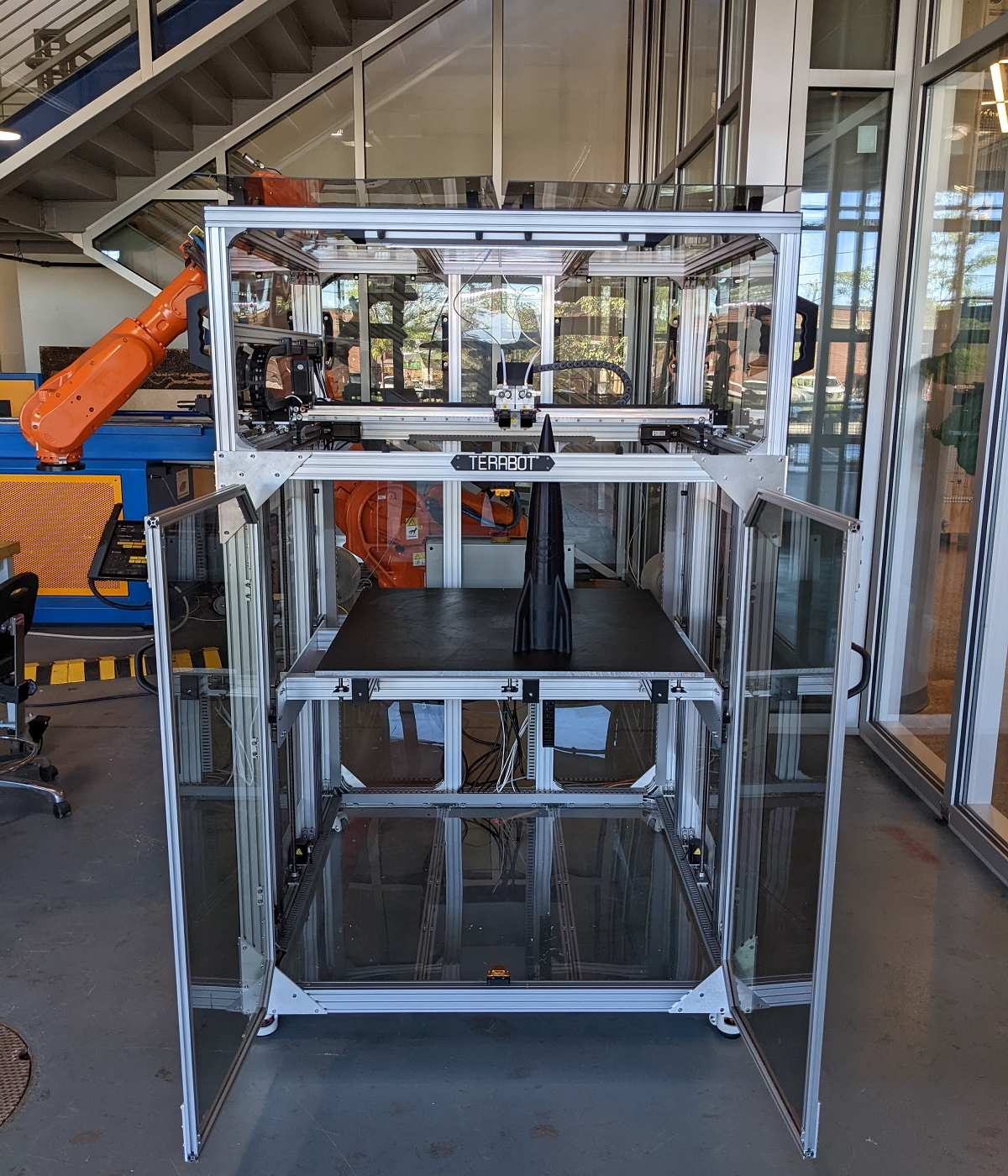
A Terabot large format 3d printer with a 3d printed rocket sitting on the bed.
Terabot 4 installed at Autodesk Technology Center, Boston, MA

Charlotte craff

Blog Post Author

Gigabot Engineering Updates – April 2022

Hi Gigabot family! It’s been a few months since we posted an engineering update, but re:3D’s engineers have been far from idle. We’ve made some further improvements to the new Metal Body Extruders and created an entirely new hot end to keep pushing the Gigabot to produce better and better results and improve your user experience. See below for details on what has changed. Current Gigabot®, Gigabot® X, Exabot® and Terabot® owners can order these as replacement parts that are upgradable from previous versions.

New Parts

Gigabot® 3+, Terabot®, Exabot®

  • 20 Series Hot Ends – Replacing the Mondo Hot End, the re:3D 20 Series Hot End was created by our engineers and machinists to increase the max flow rate of polymer deposition. With a greater flow rate, parts can print faster, reducing production time and cost. The 20 Series Hot End achieves this with a 20mm long heater block wrapped in Nomex® insulation. It comes standard with an A2 hardened steel nozzle for printing with abrasive materials like carbon-filled polymers. You can select either 0.4mm or 0.8mm nozzle size for your application.
  • 20 Series Fan Mounts – Fan mounts specific for the new 20 Series Hot End, these direct airflow to your prints for cooling.
  • Terabot only: Bed Frame Stands – an accessory for Terabot to aid in resetting the bed leveling.

Fit and Strength Part Adjustments

The below parts have had geometry changes or other additions to make them stronger or fit more precisely.

Gigabot® 3+, Terabot®, Exabot®

  • Metal Body Extruders- transitioned the new Metal Body Extruders from an aluminum frame and plastic inset to a complete aluminum piece. 
  • Light Strip Cover – redesigned to fit new LED light strip with on/off switch 

Gigabot® X

  • Gigabot X Extruder Cover – fit and tolerance adjustments. more secure mounting
  • Motor Spacer – added wire management clips for all connections to the extruder
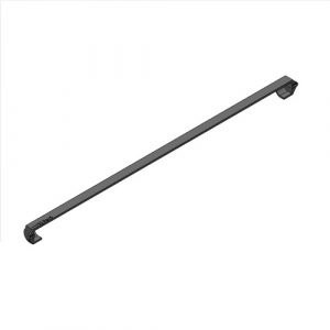
  • End Rail Caps – covering the ends of the aluminum extrusion on the X cross rail.

Firmware

Gigabot® X 4.2.4.2 Reg

This release is GBX 4.2.4 with some bug fixes discovered after the release of GBX 4.2.4. The fixes are:

  • Updating the GBX Regular build volume in the X, Y, and Z dimensions
  • Updating the GBX XLT build volume in the X, Y, and Z dimensions
  • Adjusting the minimum temperature for the heat sink fan from 18C to 60C

Check out additional update on our Forum. Want to chat with an engineer to share feedback on your Gigabot & re:3D design priorities? Email info@re3d.org.

Happy Printing!

~Your Gigabot Engineering Team

re:3D Receives CTA Company of the Year Award

November 11, 2021 –  re:3D Co-founders Samantha Snabes and Matthew Fiedler were honored to accept the CTA Company of the Year Award in a ceremony held at the Metropolitan Pavilion in New York City.

Samantha Snabes and Matthew Fiedler pose with Gary Shapiro and the Company of the Year Award.
From Left: Gary Shapiro, President of the Consumer Technology Association with Samantha Snabes and Matthew Fiedler, re:3D Co-founders

The following is a repost of an article written by Cindi Stevens which can originally be seen on CTA’s website here.

CTA Names Seven Industry Leaders to the 2020 CT Hall of Fame, will also Honor Three Innovation Entrepreneurs

The Consumer Technology Association® (CTA) announced the new class of honorees into its 2020 Consumer Technology (CT) Hall of Fame created in 2000. The program celebrates technology leaders who advance innovation and develop, create, market and promote the technologies, products and services that improve consumers’ lives.

“We are thrilled to honor these industry luminaries,” said Gary Shapiro, president and CEO, CTA. “We honor the entrepreneurial spirit of these leaders who inspire us by taking a great idea and transforming it into a unique product or service to enhance consumers’ lives, and those who promote these new technologies in the marketplace.”

The 2020 CT Hall of Fame class includes:

Vinton Gray “Vint” Cerf, along with Robert Elliot “Bob” Kahn – dubbed as the “Fathers of the Internet,” – led the development of TCP/IP (Transmission Control Protocol/Internet Protocol), the fundamental communications protocols that enable data to be transmitted over the internet.

Frank Conrad, a radio engineering and broadcast pioneer, designed the first factory-produced consumer electronics product, the RA-DA radio, in November 1920, which inaugurated the consumer electronics business.

Peter Fannon played a key role in the development of HDTV as president of the Advanced Television Test Center, then spent 20 years promoting the consumer technology industry as VP of corporate and government affairs for Panasonic.

Kazuo Kaz” Hirai led the effort that made Sony PlayStation the dominant video game console platform, then, as president, CEO and chairperson of Sony, led the resurgence of the company in the 2010s by bringing together its electronics and entertainment divisions.

Jim Meyer, an RCA/Thomson product management executive, played a central role in the launch of direct-to-home satellite TV, and as CEO led SiriusXM to be U.S.’s largest audio entertainment company, including music streamer Pandora and podcasting pioneer Stitcher.

Robin Raskin, an industry journalist, was a columnist for USA Today online, editor of PC Magazine, started FamilyPC Magazine, was one of the founding contributors of Yahoo! Tech and has written six books. She also is the founder of Living in Digital Times, that produced tech conference tracks at CES.

In addition to these seven honorees, for the second year, the program will also recognize CTA’s Innovation Entrepreneur Award winners – a top executive leading a company with revenues under $30 million, an exceptional small business and a startup that demonstrates innovation in the consumer technology industry. The honorees are:

Executive of the Year: Vicki Mayo
Mayo founded TouchPoints in 2016, using its patent-pending BLAST (bi-lateral alternating stimulation-tactile technology), which alters the body’s “fight or flight” response caused by stress. When she was 20 and in college, she adopted two boys and today mentors’ young women at the Boys and Girls Club.

Company of the Year: re:3D, Inc.
After traveling with Engineers Without Borders-Johnson Space Center and while still working for NASA in 2013, Samantha Snabes founded re:3D, Inc. The company manufactures Gigabot, an affordable industrial 3D printer that can directly print from plastic waste, allowing anyone worldwide to access their own personal 3D factory.

Startup of the Year: Nuro
Nuro was founded by Dave Ferguson and Jiajun Zhu in 2016, using their expertise in self-driving vehicle technology. Focused on delivery rather than carrying passengers, Nuro is building a new class of safe self-driving vehicles, built for goods delivery across multiple verticals and has partnered with CVS, Domino’s, Kroger and Walmart.

The honorees for the CT Hall of Fame and the Innovation Entrepreneur Awards were selected by two separate panels of media and industry professionals, who judged nominations submitted by manufacturers, retailers and industry journalists. The annual awards dinner, originally slated for November 12 in New York City, is postponed until 2021 due to restrictions with COVID-19. Complete inductee bios will appear in CTA’s It Is Innovation (i3) magazine, as well as online at CTA.tech/i3.

For more information, visit CTA.tech/events.

Charlotte craff

Blog Post Author

Gigabot Engineering Updates – September 2021

An aluminum dual extrusion extruder for a 3d printer

re:3D engineers have spent the last few months making some exciting changes to our product lines. re:3D 3D printers are shipping with some great new enhancements. Current Gigabot®, Gigabot® X, Exabot® and Terabot® owners can order these as replacement parts that are upgradable from previous versions.

New Parts

Gigabot® 3+, Terabot®, Exabot®

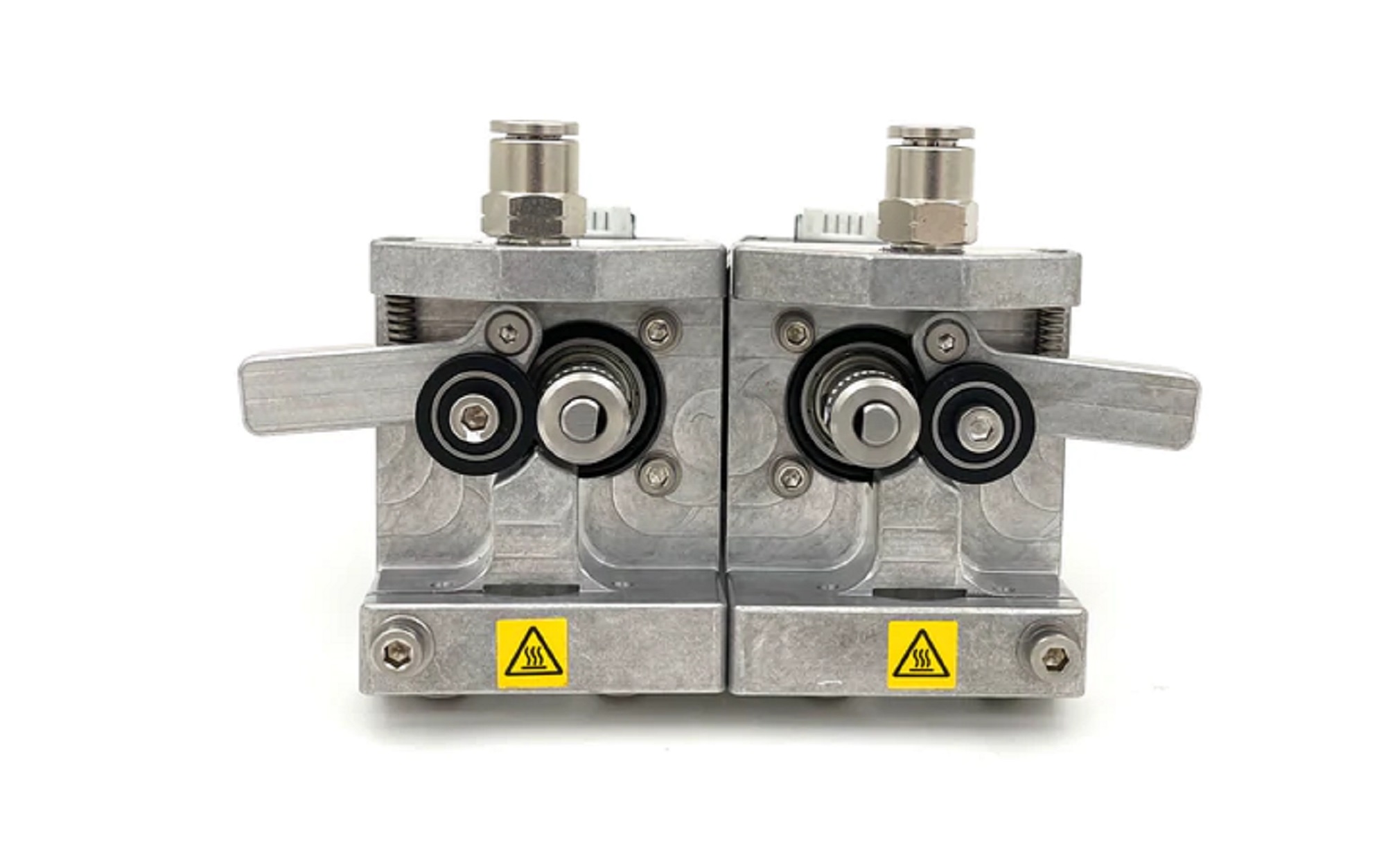
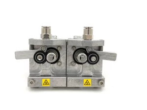
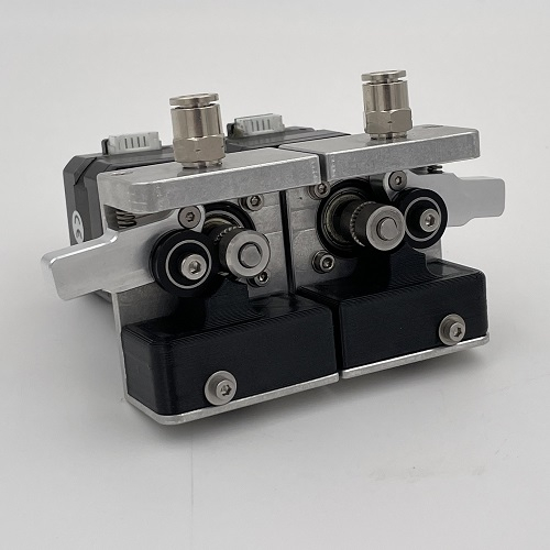
  • Metal Body Extruder – 2 pieces, left and right. The metal body extruder replaces the unibody extruder on re:3D filament-based, dual extrusion 3d printers. High-strength aluminum housing and tensioner arm for a long-lasting, industrial extruder.
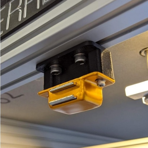
  • Terabot Magnetic Catch – Magnetic latch for Terabot enclosure doors

Fit and Strength Part Adjustments

The below parts have had geometry changes or other additions to make them stronger or fit more precisely.

Gigabot® 3+, Terabot®, Exabot®

  • Filament Detection Covers – Improved fit for easier removal
  • LED Light Cover – Redesigned to fit new led strip, plus improved durability when used in enclosures 
  • GB3+ X Axis Cable Carrier Support – Strengthened for greater durability
  • GB3+ XY Upright – Revised to fit larger wiring, better print quality and durability of interface with cable carrier
  • Mondo Hot End Fan Mounts (Left & Right) – Revised fan placement for better part cooling

Check out additional update on our Forum. Want to chat with an engineer to share feedback on your Gigabot & re:3D design priorities? Email info@re3d.org.

Happy Printing!

~Your Gigabot Engineering Team

re:3D Supplies Parts for Testing America Makes AMCPR Exchange

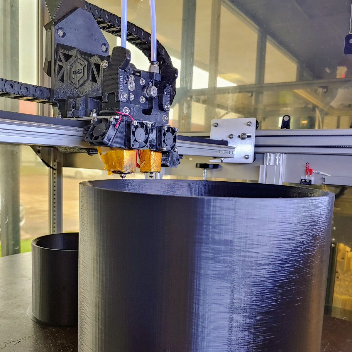
A gigabot 3d printer, printing a black 8 inch coupling.

re:3D had the honor of helping to stress test AMCPR, America Makes’ new exchange for enabling rapid additive manufacturing production responses during times of crisis, like we did at the outset of the COVID-19 pandemic.

America Makes developed the AMCPR exchange to be a long lasting solution to host design files, review them for safety, and, when needed, distribute them to the US’s additive manufacturing community for production.

Part way through the development process America Makes reached out to members seeking participants to help test the exchange, and re:3D answered the call along with our peers in the 3d printing industry.

We took part in a mock-crisis scenario called Earthquakes Earn Enmity, designed to simulate a response to an earthquake which crippled water delivery systems, otherwise known as pipes!

Ironically just as we were kicking off the mock-crisis, we were faced with a real crisis here in Texas: A hard freeze dropped temperatures to record lows all across the state, and many lost power as the power grids failed to keep up with demand. Pipes burst and created a shortage of plumbing supplies. It illustrated in very real detail how important this AMCPR exchange can be where additive manufacturing can step in during crisis to quickly increase product supplies when traditional manufacturing has to wait to retool their factories.

We met over the course of two month to walk through testing. The first step was to design pipe couplings that could be successfully manufactured with 3D printing. This work was done by a team at the University of Texas at El Paso. The designs were reviewed by America Makes and validated by a separate team at UT El Paso who had not been involved in the original design work. They used the AMCPR exchange to submit and review and finally approve the designs for use on the exchange.

Gigabot 3+ 3D Printing AMCPR Couplings

After the design process, re:3D stepped in as a supplier along with Rapid Application Group, IC3D, Stratasys and Markforged to 3D print the requested couplings. We downloaded the technical data package from the AMCPR exchange, reviewed it with our contract printing team, sliced the included stl files according to their required parameters, and produced three example couplings on Gigabot 3+ XLT out of ABS filament. The three couplings measured 2”, 4” and 8” in diameter. To complete the scenario we each mailed the printed couplings to ASTM International, who was acting as the requestor in our case.

Throughout the process, we advised America Makes on clarifications and revisions the AMCPR exchange needed to improve the usability and accessibility of the system. Things like the variables that different industrial FDM 3D printers have as far as materials, size, and slicing, as well as enhancements to communications and troubleshooting.

One of the highlights for us of helping test the system was participating in some final testing walkthroughs with our customer and fellow America Makes member Pampton 3D. We got to observe how the improvements that had been made in only a few short months eased Pam’s experience first using the AMCPR exchange.

Now that this testing is done and the AMCPR exchange is live, We invite you to join us on the exchange by creating an account to be a designer, supplier or a requestor, so that together with your skills and ingenuity, when we face our next crisis, we’ll all be ready.

To read more about the AMCPR scenario testing, view the America Makes press release and presentation.

Charlotte craff

Blog Post Author