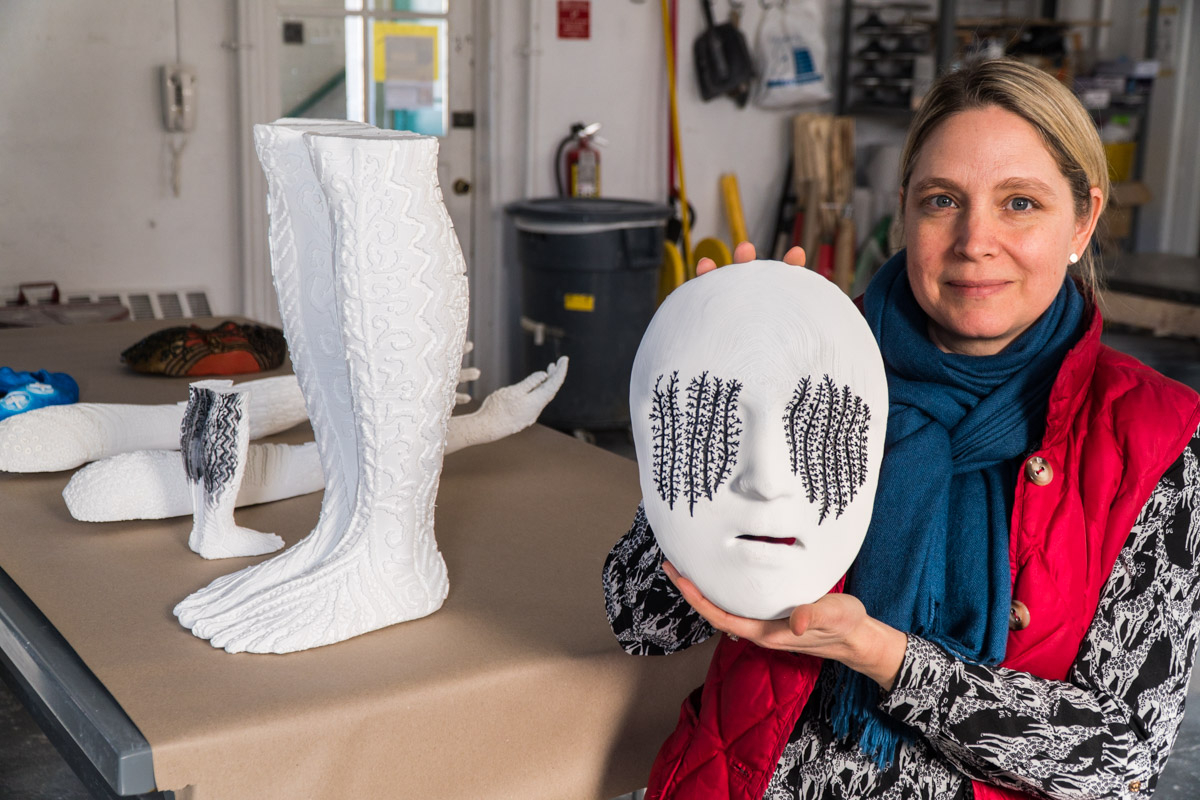
“It is certainly a beautiful campus in which to construct a temporary play structure. It also meant that I would walk by the installation every day on my way to and from work, allowing me to observe the structure over time and learn more about the novel construction system.”
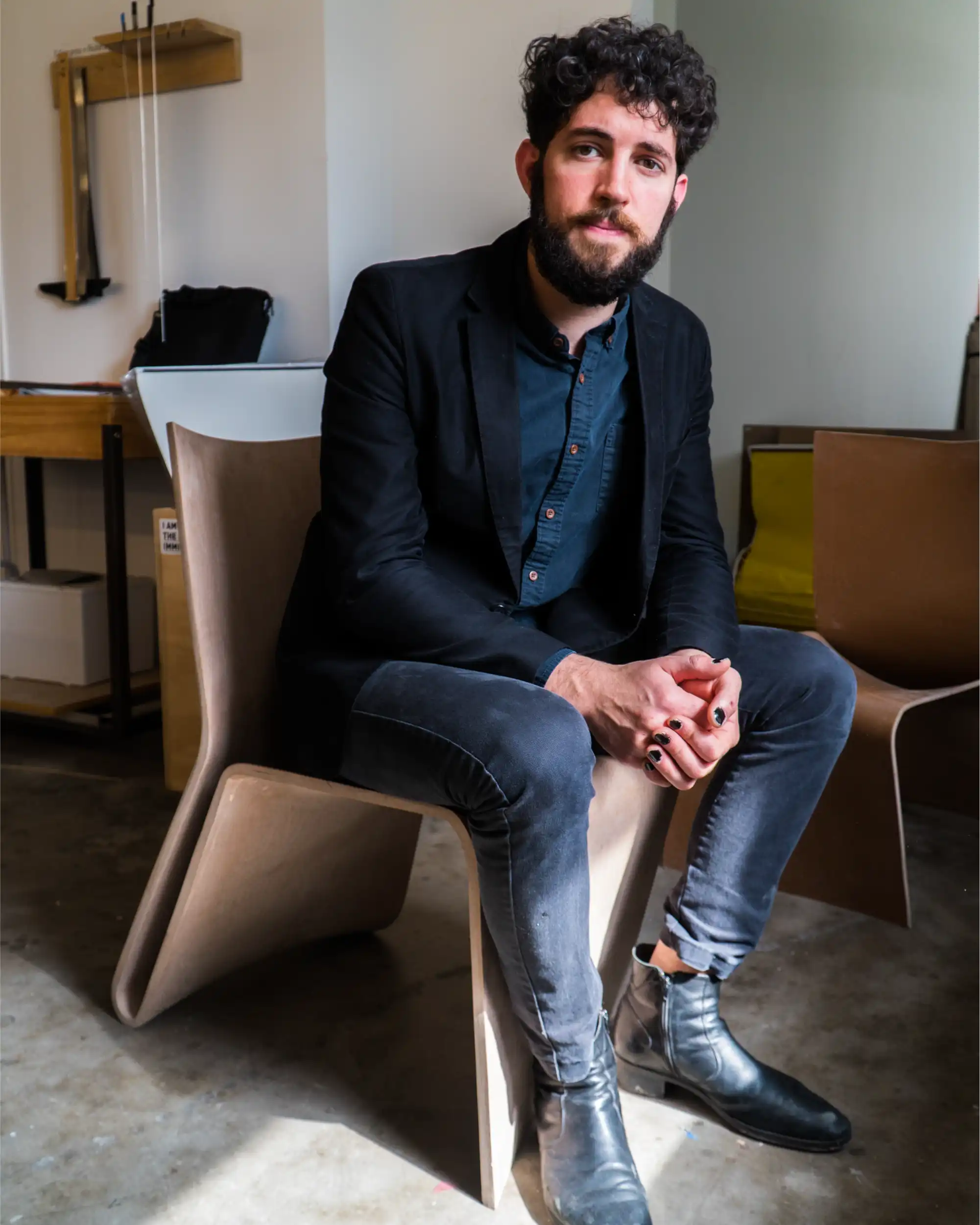
David Costanza, now teaching at Cornell AAP’s Department of Architecture, was a Technology Fellow at Rice University’s School of Architecture at the time of this visit, where he taught for four years.
In Model Object, a Rice seminar that Costanza co-taught with Assistant Professor Andrew Colopy, students explored issues of digital modeling and fabrication through focuses on additive manufacturing, subtractive manufacturing, and cutting.
Costanza came from MIT where he got his M.Arch and S.MarchS, a postgraduate research degree. He was involved in a number of design and fabrication courses there, including as a teaching assistant for the class “How to Make Almost Anything,” where they were heavily invested in 3D printing. At Rice, one of his undertakings as a technology fellow was to restructure the building technology sequence in the School of Architecture, where he worked to incorporate more contemporary and digital tools for design, representation, and manufacturing.
Thanks to his heavy involvement with 3D printing during his time at MIT, Costanza brought a strong additive manufacturing background with him to Rice. This skillset helped him spearhead the bulking up of Rice’s 3D printer arsenal, where he used each machine as a stepping stone to the next level.
Sizing Up Rice's Printer Arsenal
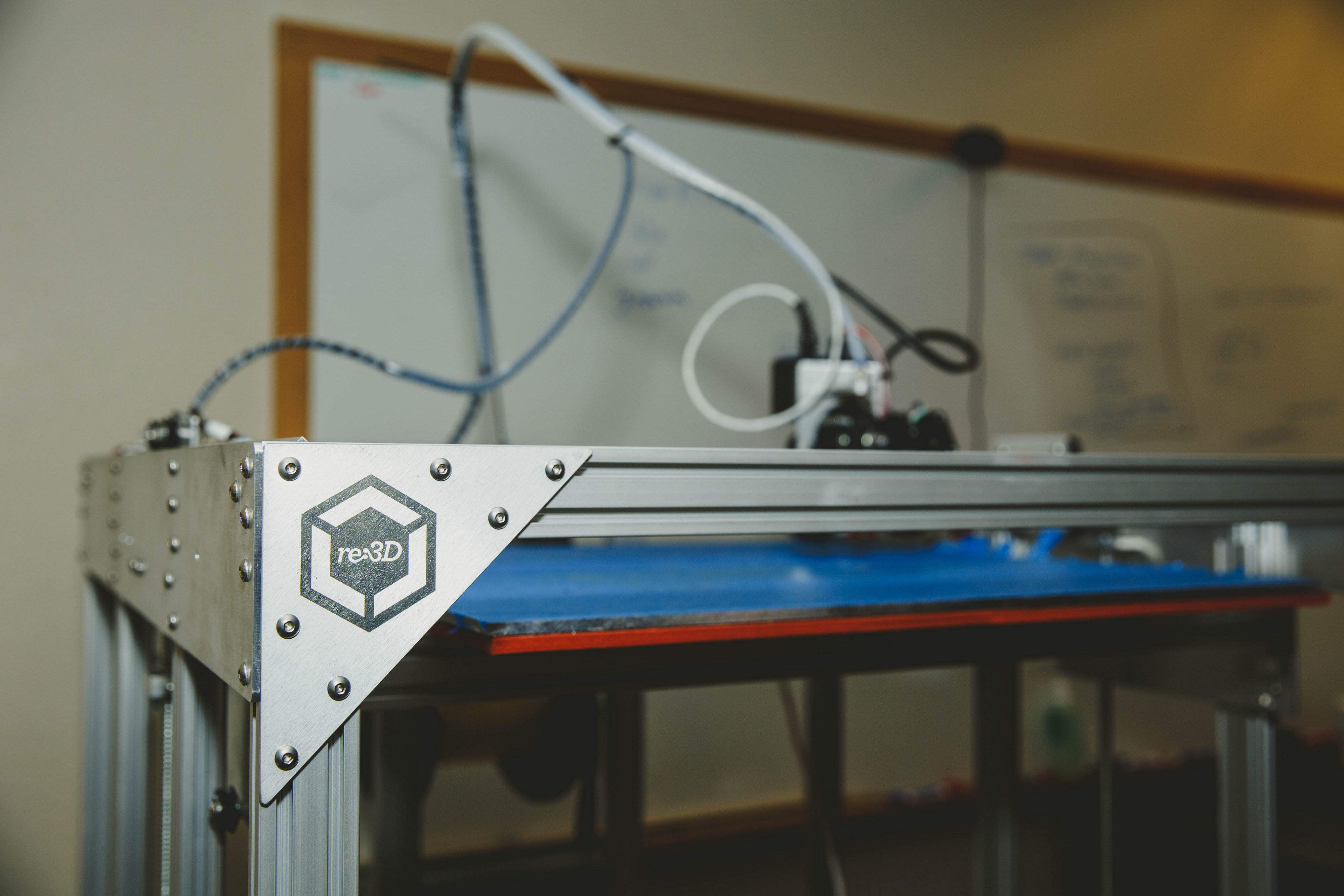
When Costanza arrived at Rice, the department had one desktop SLA printer. In his first semester teaching Model Object, he and Colopy wrote a grant and were able to buy a series of Ultimakers, or desktop FFF printers. “We then used the work that was produced in that course to write a larger grant, and that allowed us to purchase the Gigabot,” he explains, “to allow the work that we were doing and the research at the smaller scale to scale up with the larger 3D printer.”
Their shift in focus from SLA to FFF was deliberate, Costanza explains.
They considered both SLS and SLA machines, and although the print resolution is high and allows for fine detail, the technology didn’t give them what they were ultimately looking for. “We’re trying to project forward as to how those geometries might be constructed in the real world,” Costanza muses. “The same translation that we have with an architectural scale model also happens at a full-scale on the construction site. So we’re trying to project how building that model might also scale up.”
SLS and SLA technology “works really well at a small-scale,” he explains, “but they don’t really allow for the scaling up of something that might be architectural.” If they were going to be testing complex geometries that would ultimately be building-sized, they wanted to be sure they were doing so using a method that was actually representative of real world construction.
“Because we’re very interested in the full scale here in the Architecture Department, we can really treat [an extruded] model as something that could scale up,” Costanza explains. “The thing that we’re printing on the Ultimaker can scale up to the Gigabot, and the thing on the Gigabot can scale up to a Kuka arm with [an] extruder at the end of a gantry crane.”
In the real world, building construction typically happens through an additive process: concrete is poured, steel is erected, bricks are laid, et cetera. A 3D print created using fused filament fabrication would therefore be a more realistic representation of how that structure would ultimately come to be. “Where the other models – SLS, SLA – would produce objects that were purely representational,” Costanza continues, “by using an [FFF] printer, we could essentially replicate – more or less, at a different scale – something that could happen at an architectural scale.”
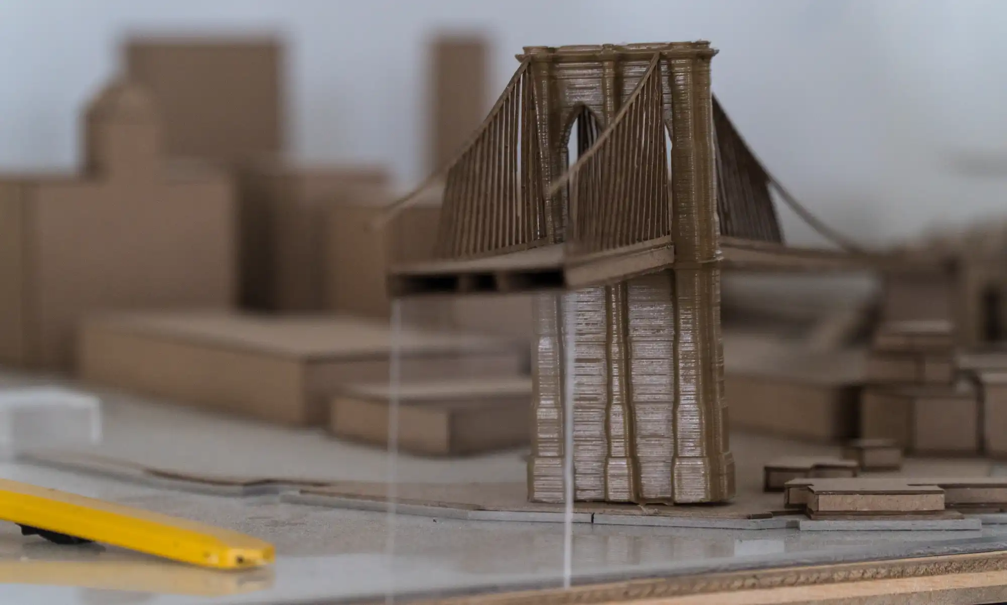
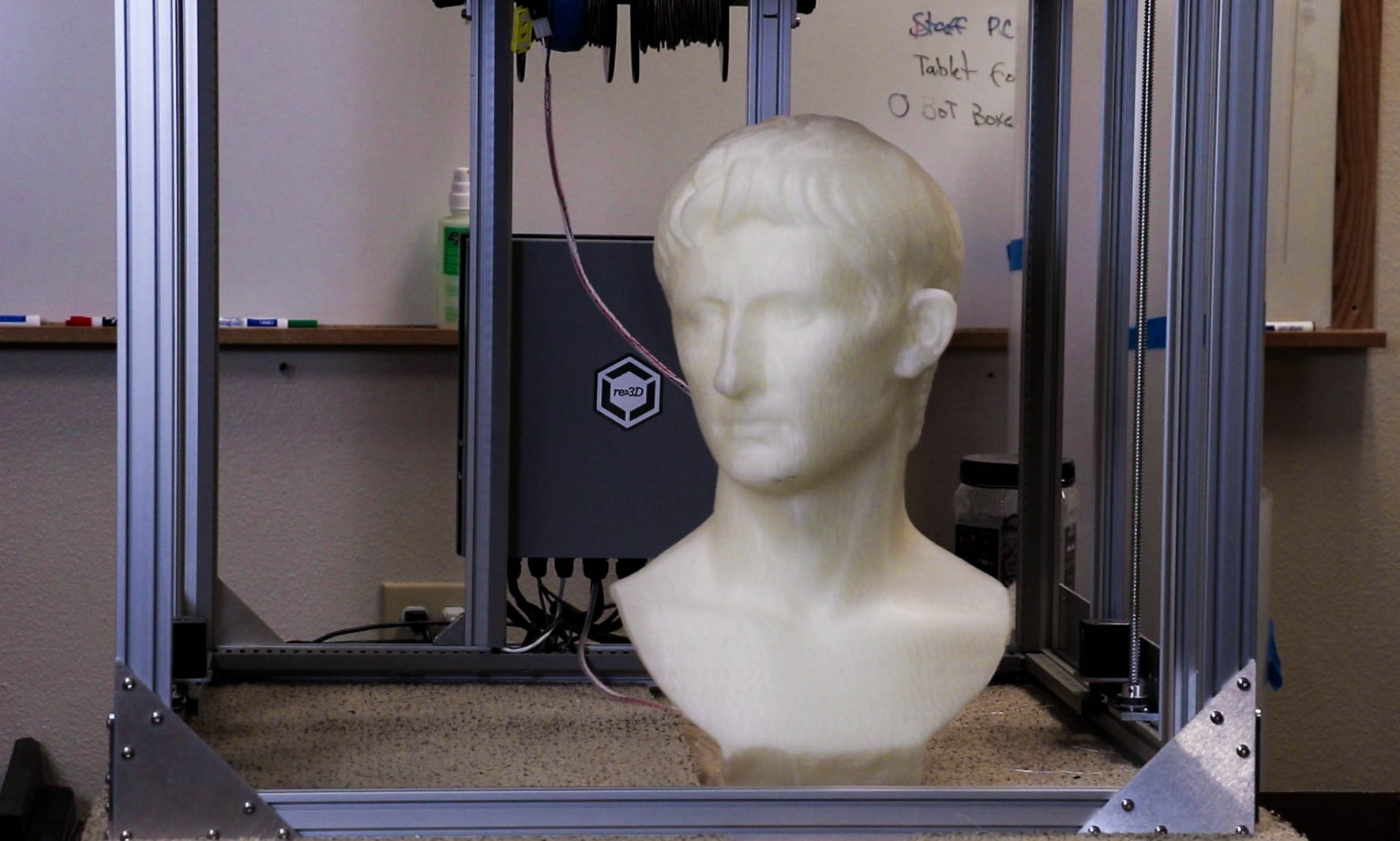
The School of Architecture is now home to a Gigabot – as of several years ago – which lives in the department’s dedicated 3D printing room and spends most of its time producing models of buildings.
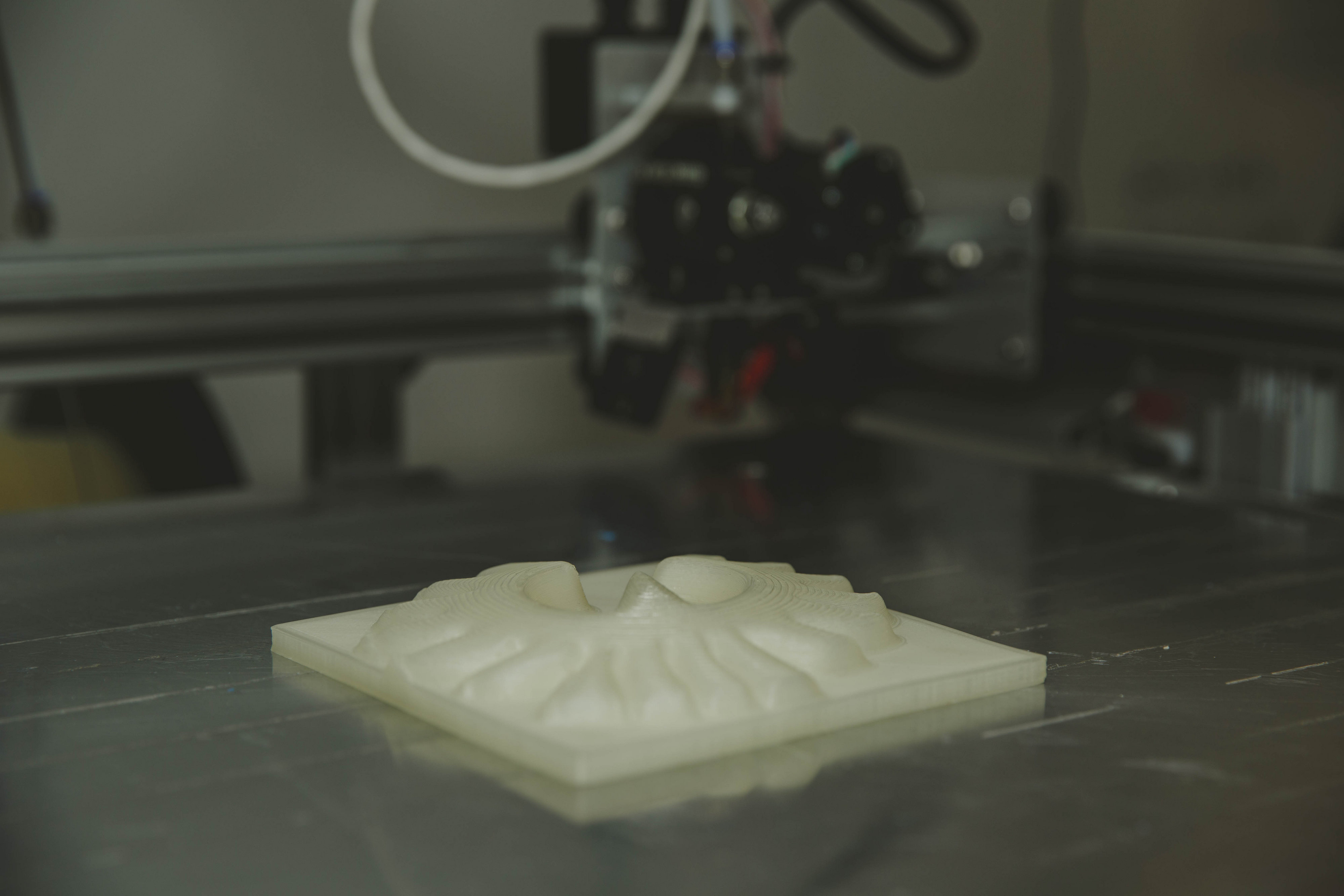
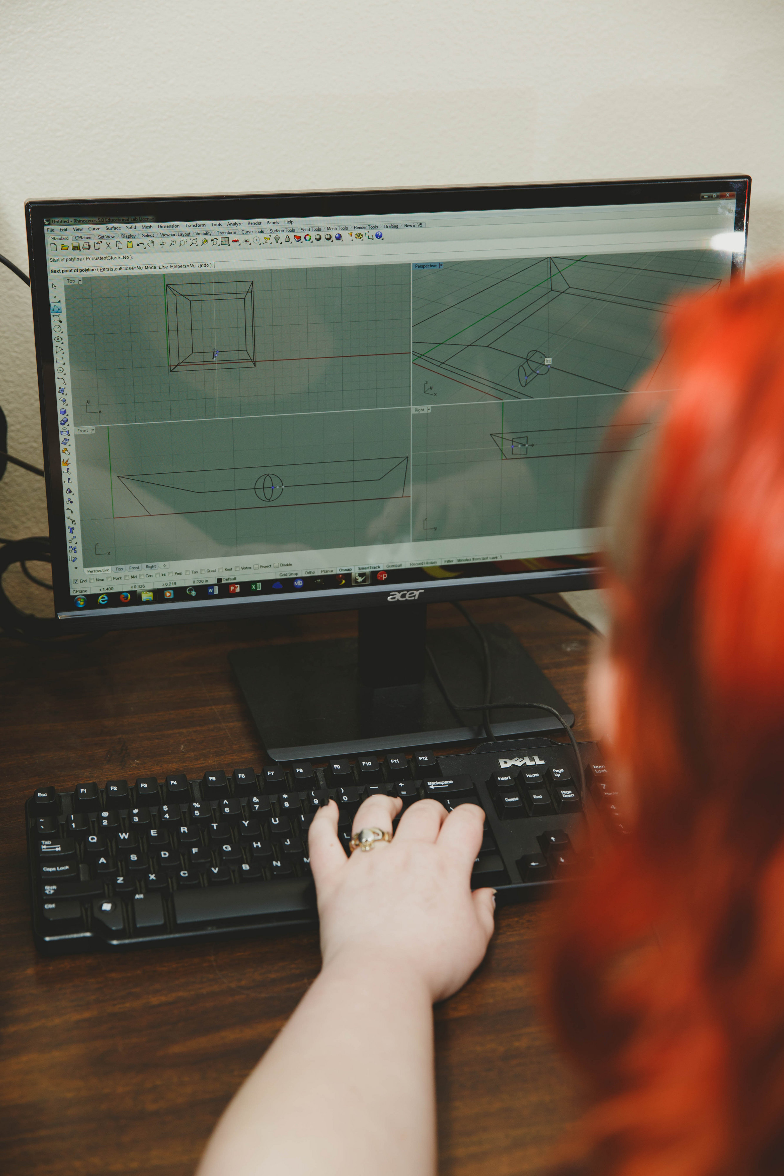
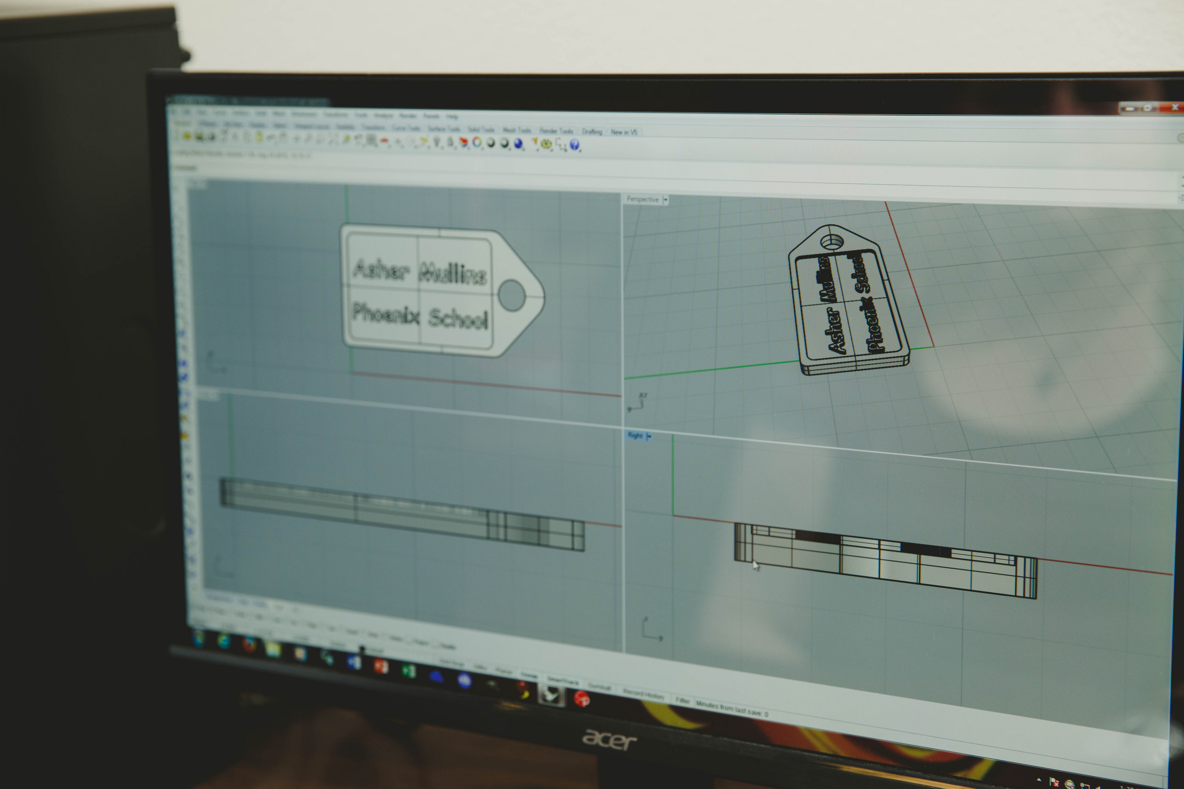
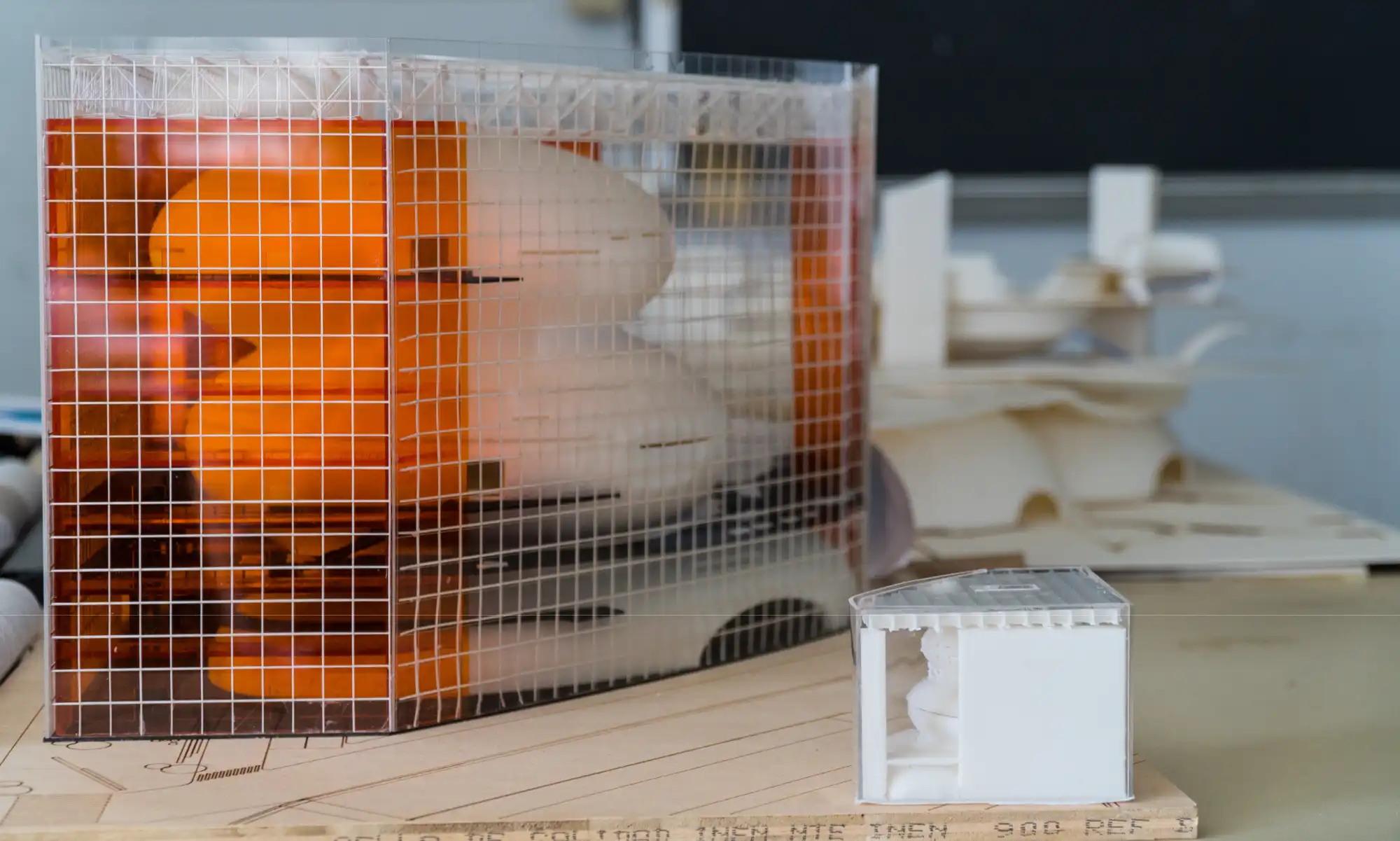
Now that architects essentially operate in a digital world – conceptualizing and designing buildings on a computer – “that translation from the digital models that we’re producing into a physical object or scale model can be quite complex for some of the geometries,” Costanza explains. “When the Gigabot is used to produce architectural representational scale models, it’s typically to produce geometry that would be otherwise quite difficult to replicate physically, but is quite simple to produce digitally.”
Beyond Architectural Models
Rice’s Gigabot also occasionally gets to spend some time on other real-world endeavors.
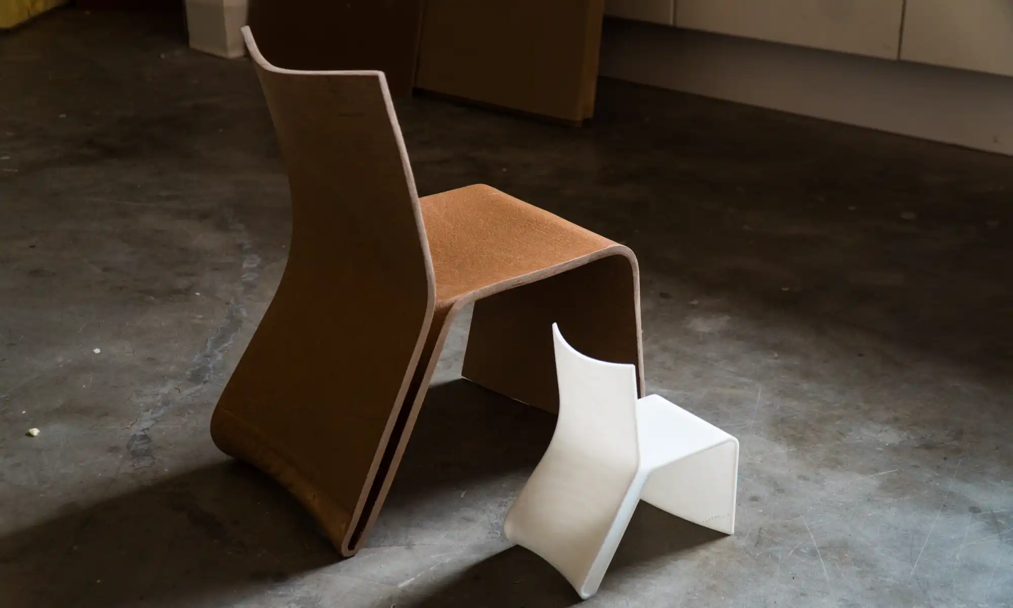
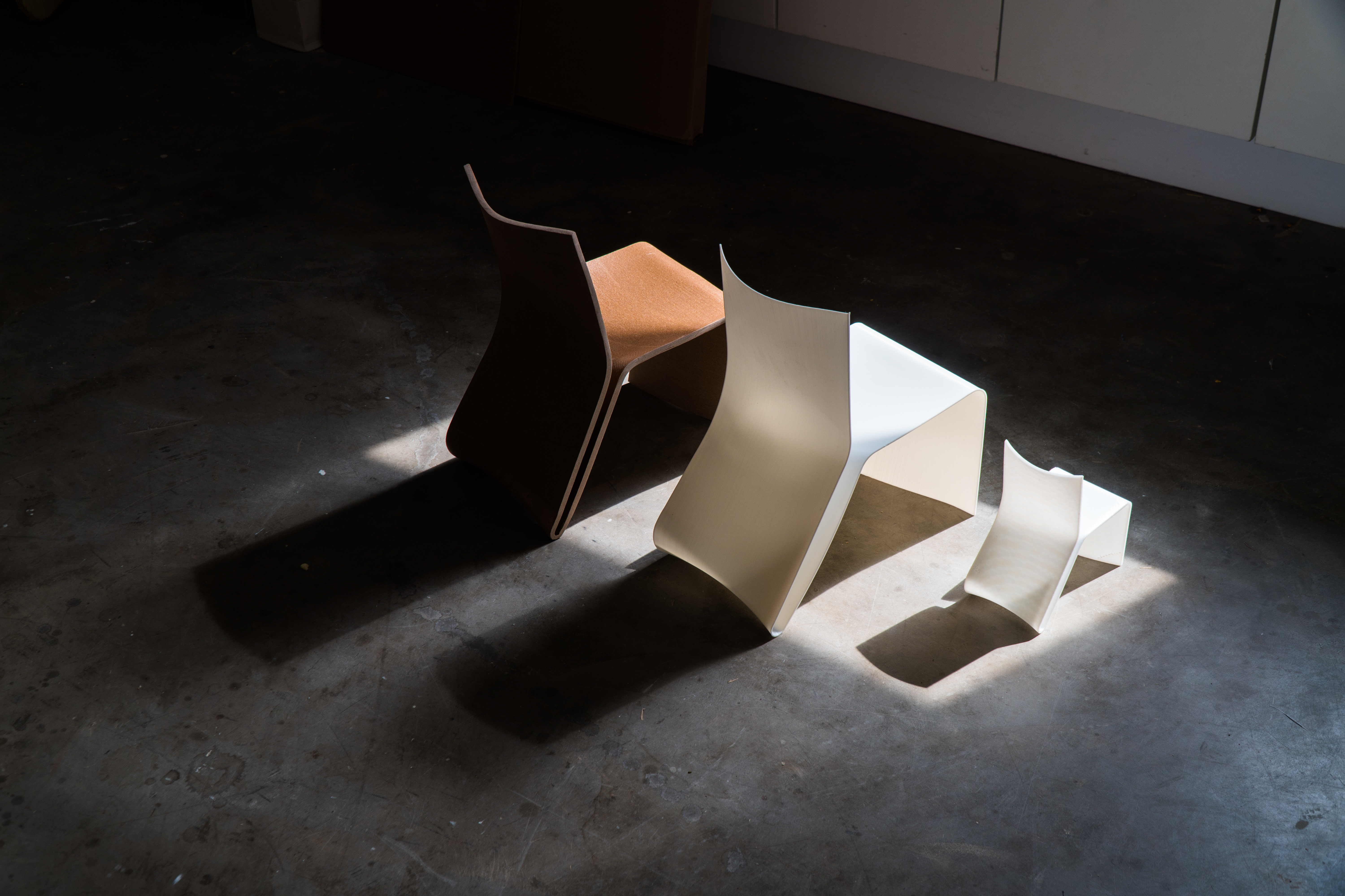
One such project was a chair that Costanza produced in collaboration with his Model Object co-teacher, Colopy. Thermoformed from a single piece of rice husk biocomposite, the final piece sports asymmetrical curves that are just as much function as they are form. The back of the chair flexes slightly to the body’s natural contours, the oblique face of the seat is perfectly angled for a natural tuck of one’s feet as it slopes to the floor, and the shape of the chair allows it to nest for packing purposes.
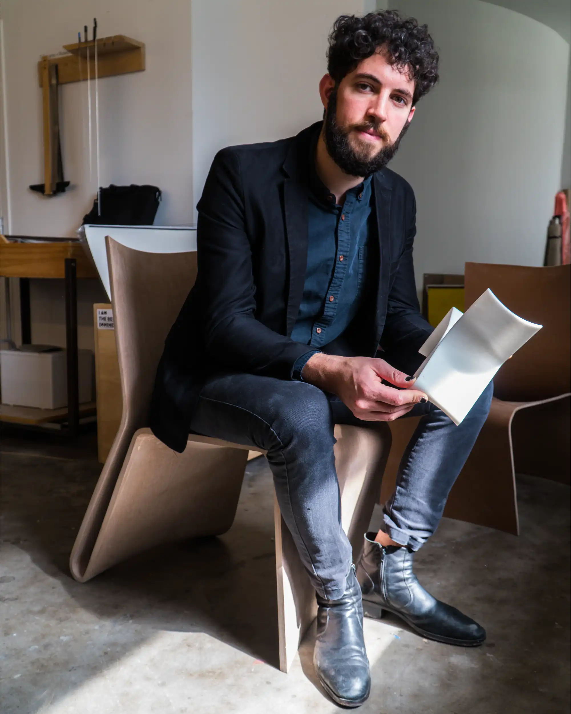
The design of the chair feels natural and obvious – as good design should – but much testing went into settling on its final form.
“As we were manipulating the geometry of the chair, the Gigabot allowed us to produce quick, iterative prototypes of how the chair might look that we could evaluate for its aesthetic qualities, but also even some of its performative qualities,” Costanza recounts.
They could use 3D prints not only to take their vision into the physical realm and allow them to turn the design over in their hands, but also to test its functionality. “To see how the plastic flexes for the back of the chair, let’s say, was something that we could test even out of PLA,” Costanza explains.
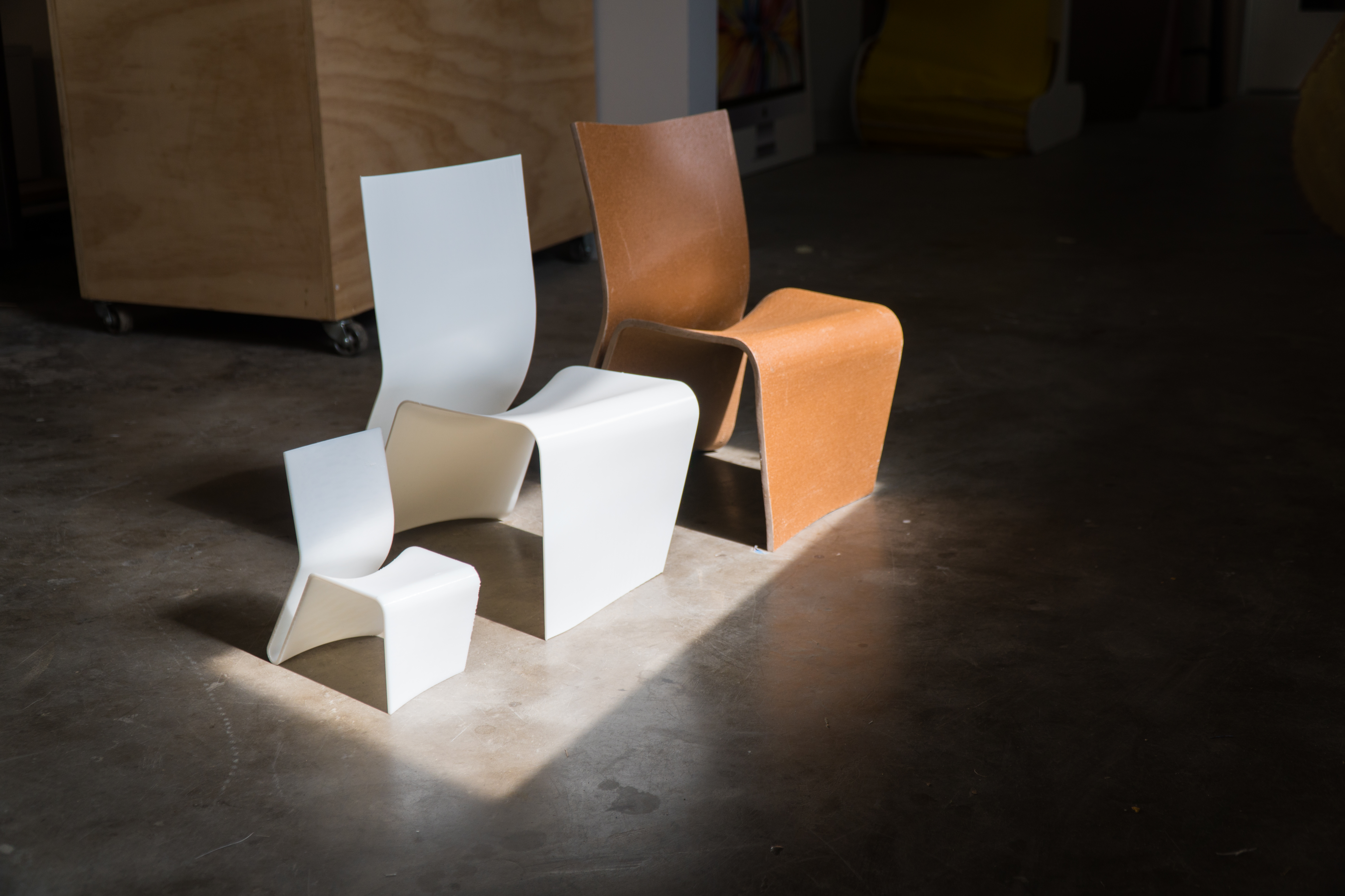
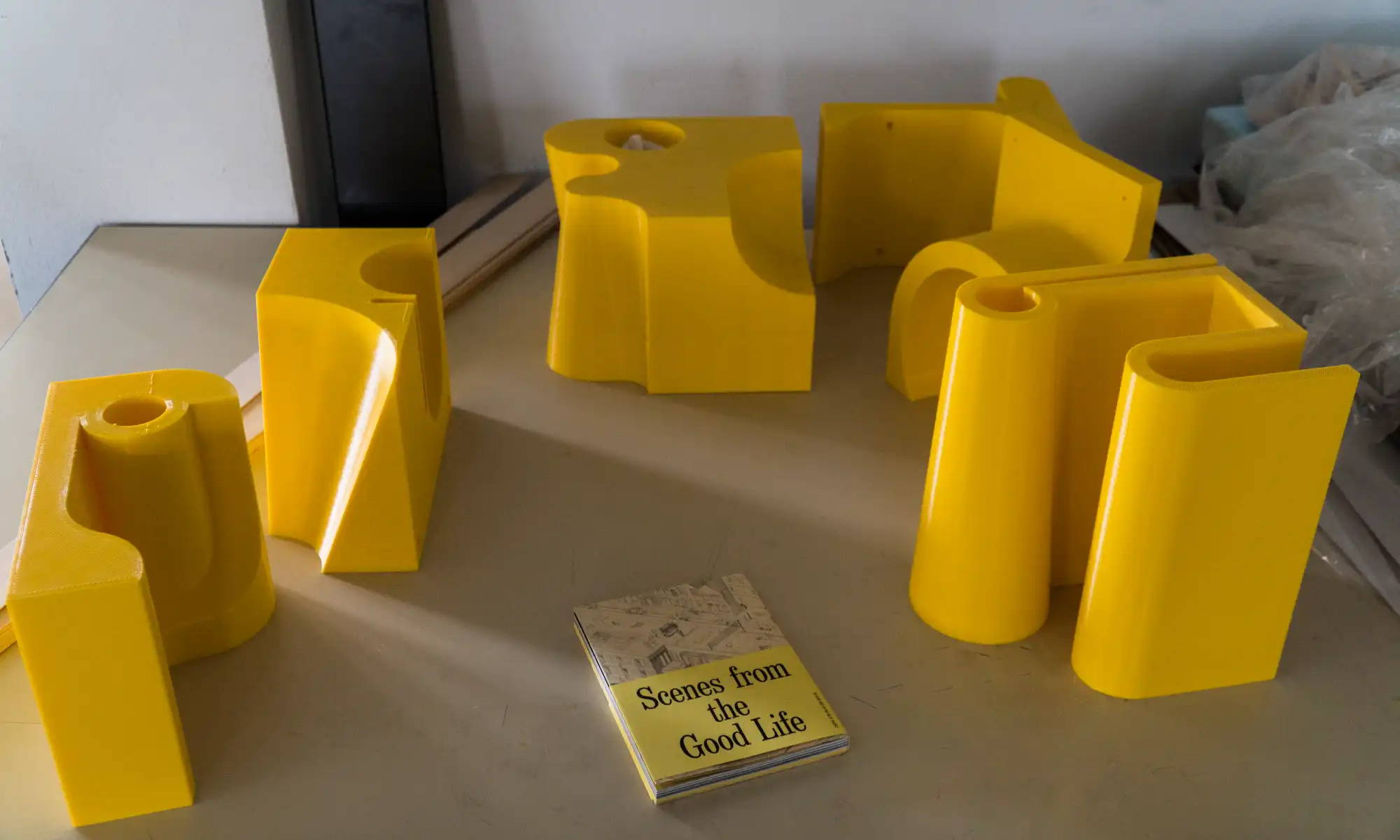
Scaled-down iterations of the chair – from palm-sized miniatures to versions big enough for a kid – still adorn one of the workshops in the architecture building. “We built a number of small scale mock-ups, all the way up to a half-scale version of the chair on the Gigabot,” recounts Costanza. “Between each iteration we were able to manipulate the double curvature of the chair, which is what produced the stiffness for the back, or the double curvature of the seat, which allowed for various degrees of comfort.”
End Use 3D Prints in a Real World Structure
Another project of Costanza’s – originally on exhibit at Lawndale Art Center in Houston – now resides on the Rice campus.
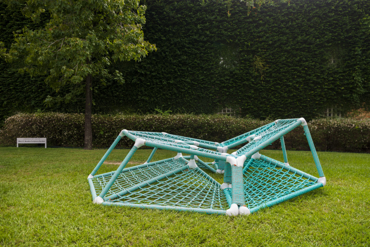
“The design of the object is a kind of communal play structure, something that would bring disparate communities together to play, where one interaction by an individual would have repercussions for someone else on the play structure,” explains Costanza. “So it’s sort of a collective bench, or possibly a see-saw made up of a series of hammocks.”
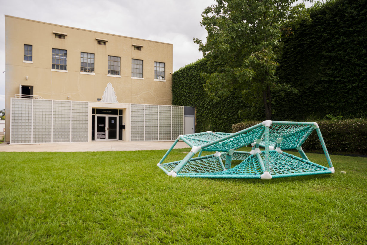
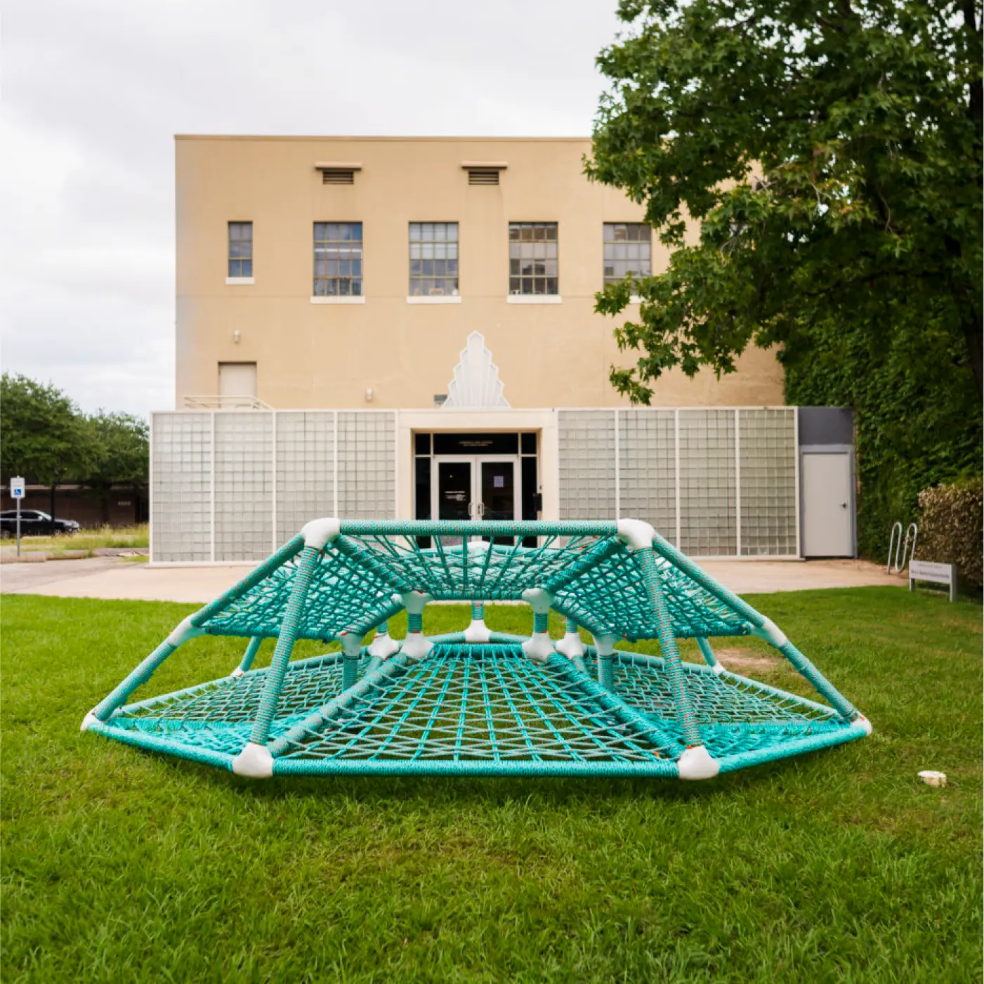
Part furniture piece, part play structure, the design sits roughly 15 feet in diameter, made up of a skeleton of fiberglass pultrusions connected with nodes and wrapped with a webbing of climbing rope. Its asymmetrical upper and lower surfaces prompt loungers to either lay down or sit upright. One design feature in particular lends the structure its name.
“Depending on the number of people that are occupying the structure, it will tip to one side or to the other,” Costanza explains. “So the name of the object is TipTap…It’s really meant to bring people together through coordinated play.”
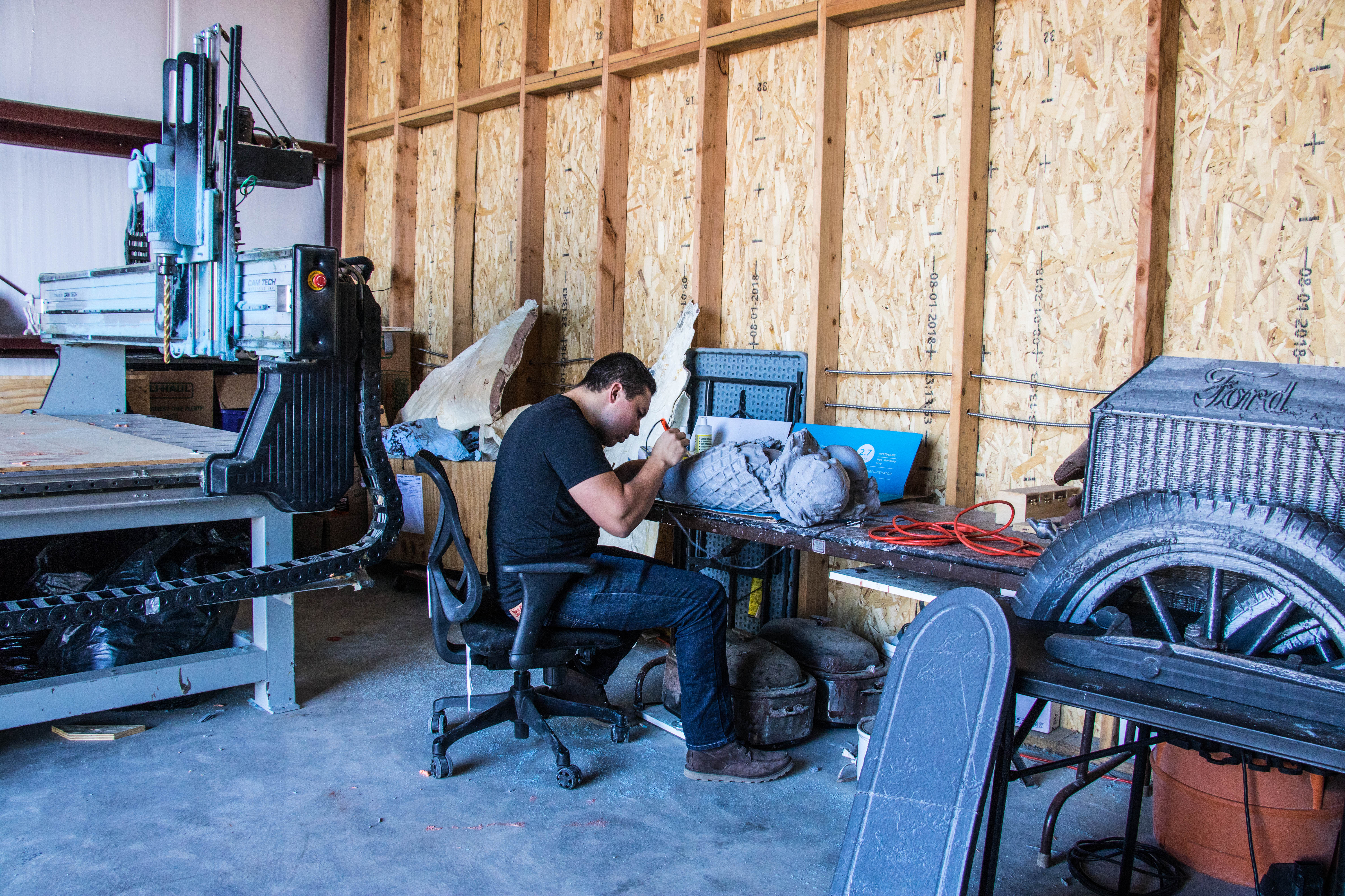
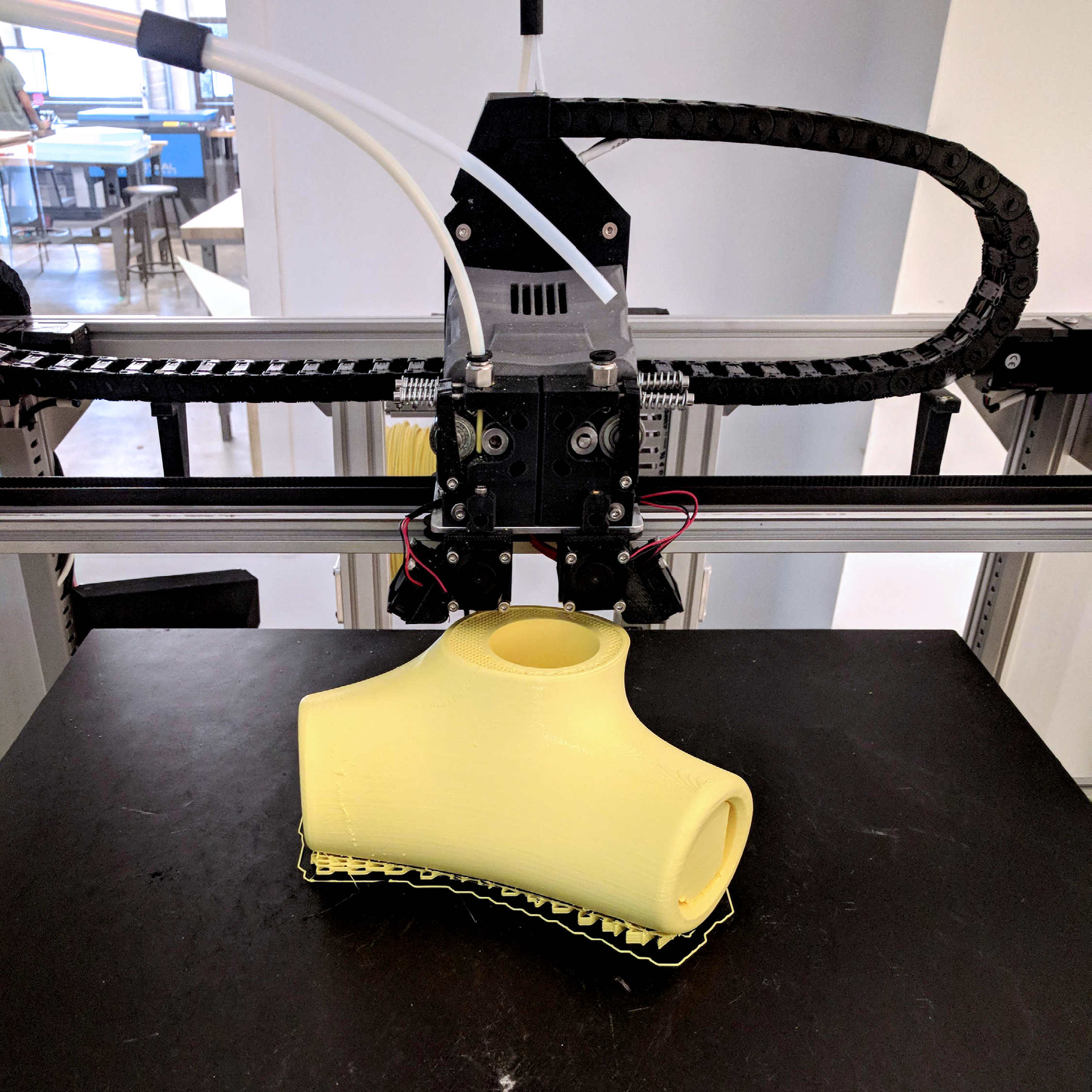
In this particular piece of work, Gigabot played more than just a prototyping role. TipTap’s structure is made up of linear, off-the-shelf fiberglass pultrusions which were simply cut to length, joined together by a series of “highly intricate, complex nodes.” Enter Gigabot.
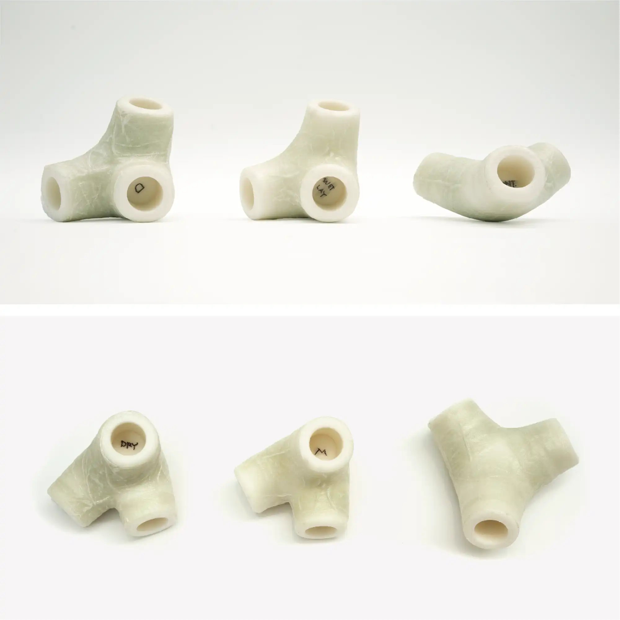
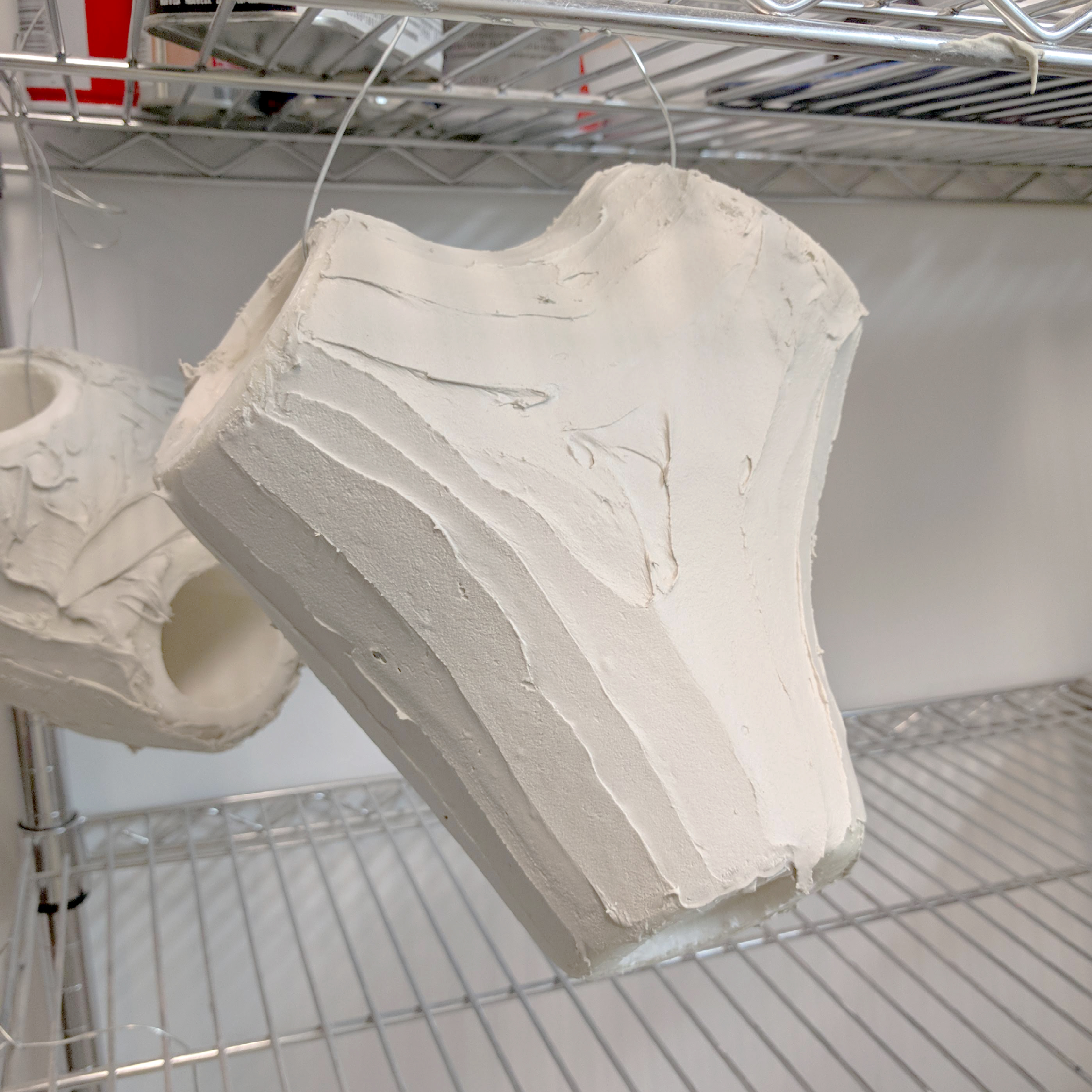
“There are 32 nodes. Each node is unique, and they were all printed on the Gigabot,” says Costanza. The nodes operate as a mold for a fiberglass shell structure: first printed, then wrapped with fiberglass tape and an epoxy resin and vacuum bagged, rendering them structurally sound.
The design of TipTap ultimately hinged on Costanza’s ability to use a large-scale 3D printer for the fabrication of the nodes. “I designed the nodes for the TipTap play structure around the scale of the Gigabot,” he explains, “knowing that they would be 3D printed, knowing how long it would take to print those objects, and the kind of scale that I could produce and the quality of those parts.”
He considered the alternatives – machining molds out of foam and fiberglassing the foam, for example – but noted that the other methods available to him would have been more time-consuming and labor-intensive than his 3D printing method.
“So in the end,” he muses, “we probably would have designed a different object if we did not have the Gigabot.”
Morgan Hamel
Blog Post Author