This is called the “Engineering” Update, but it’s really a reflection of all the work going on at re:3D – engineering, R&D, customer service, operations and everyone else included. As our company ethos begins, “We are a team…”, and that team has been working hard to solve problems for our customers, improve the performance of our products and contribute to the body of knowledge within our additive manufacturing industry. Here are a few snapshots of what’s been happening at re:3D since our last post.
The Gigabot FFF (Filament) Platform
MCU Thermocouple Errors
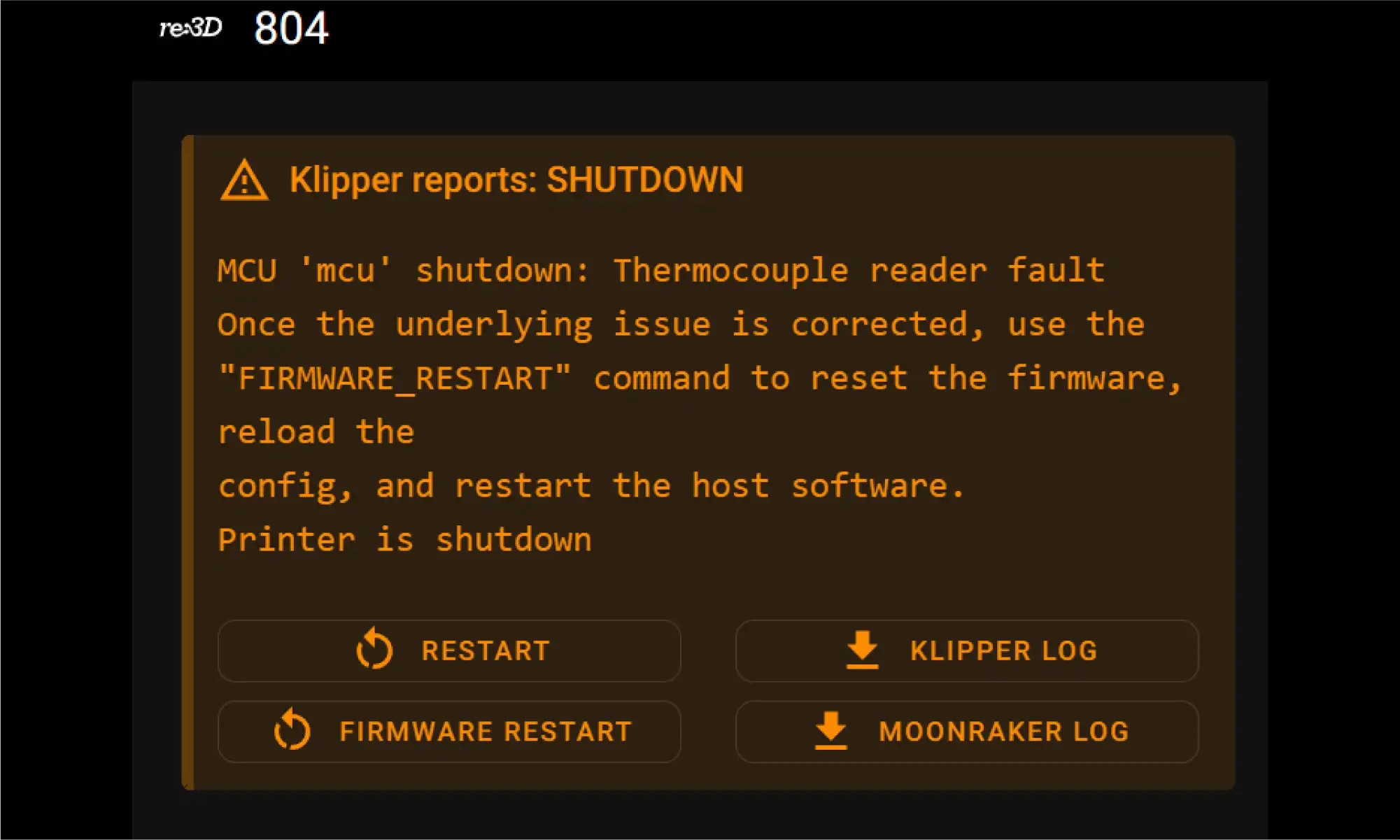
For the past couple of years, an intermittent problem would pop up on the Gigabot 4 (and GigabotX 2) printers related to the thermocouples. Sometimes the printer would throw an “MCU shutdown: Thermocouple reader error” fault during the bootup cycle (Figure 1). There were some arcane incantations that could be performed to sometimes clear the fault in any given instance, but ultimately, better grounding of the extruder seemed to solve the problem. Recently the error started showing up again, potentially delaying product shipments. So the engineering team put intense focus on investigating the cause of the error.
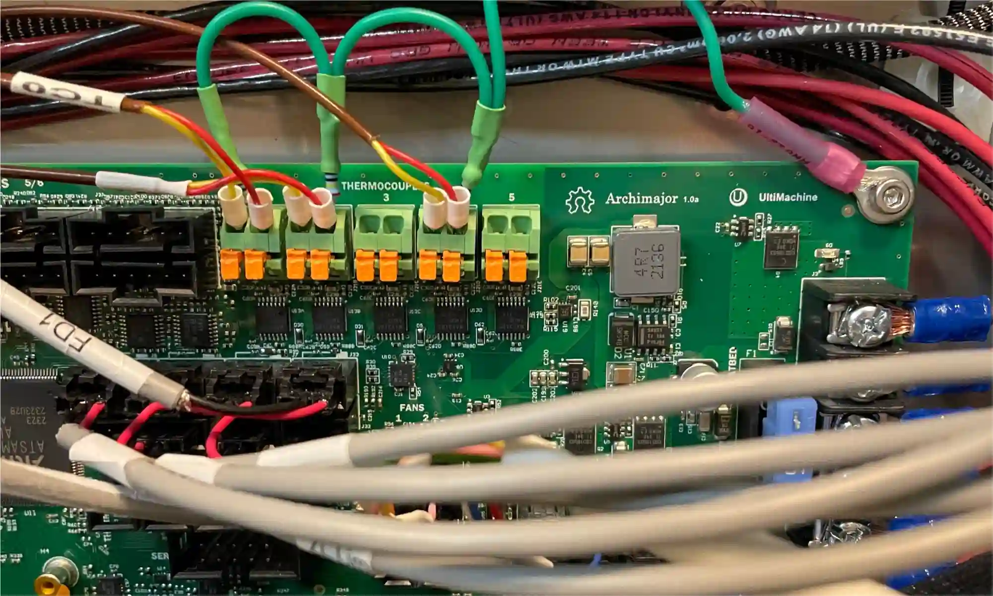
re:3D’s uses the Archimajor 3D printer motherboard from US manufacturer UltiMachine (South Pittsburg, Tennessee). The Archim boards use a MAX31856 chip from Maxim Integrated to amplify and digitize the input signals from the thermocouples, and it was this chip that was throwing the pesky error. Buried in an obscure Maxim FAQ was a cryptic comment about shunting the negative lead of the thermocouple input to ground to improve performance. The engineering team tried it out (Figure 2), and this has reliably prevented the error from occurring. re:3D now has a field-fix available for service technicians to use when encountering this issue on customer machines and is also working with UltiMachine to incorporate this feature into future versions of the motherboard.
Terabot Hot End Conversion
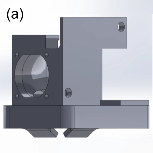
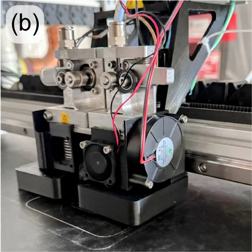
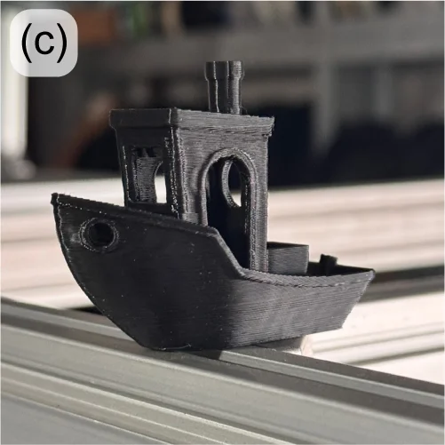
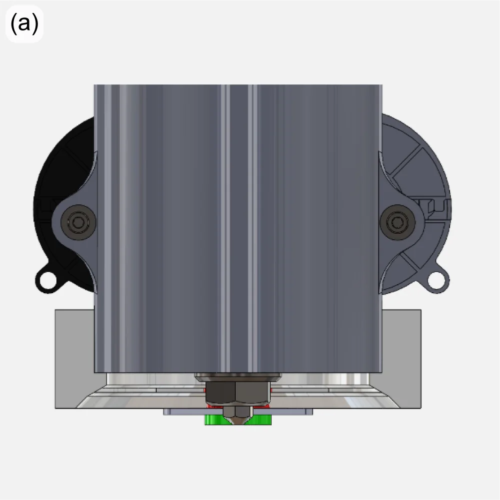
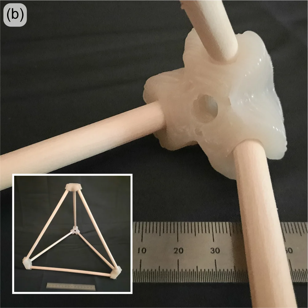
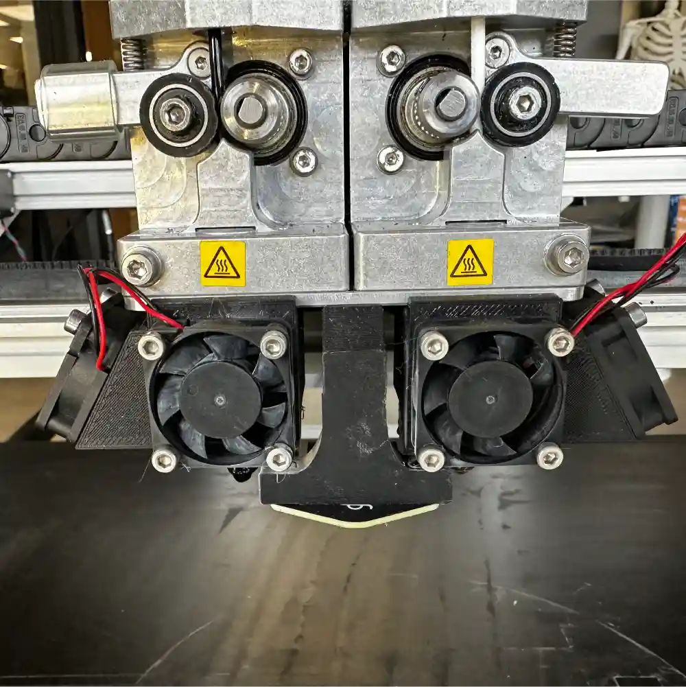
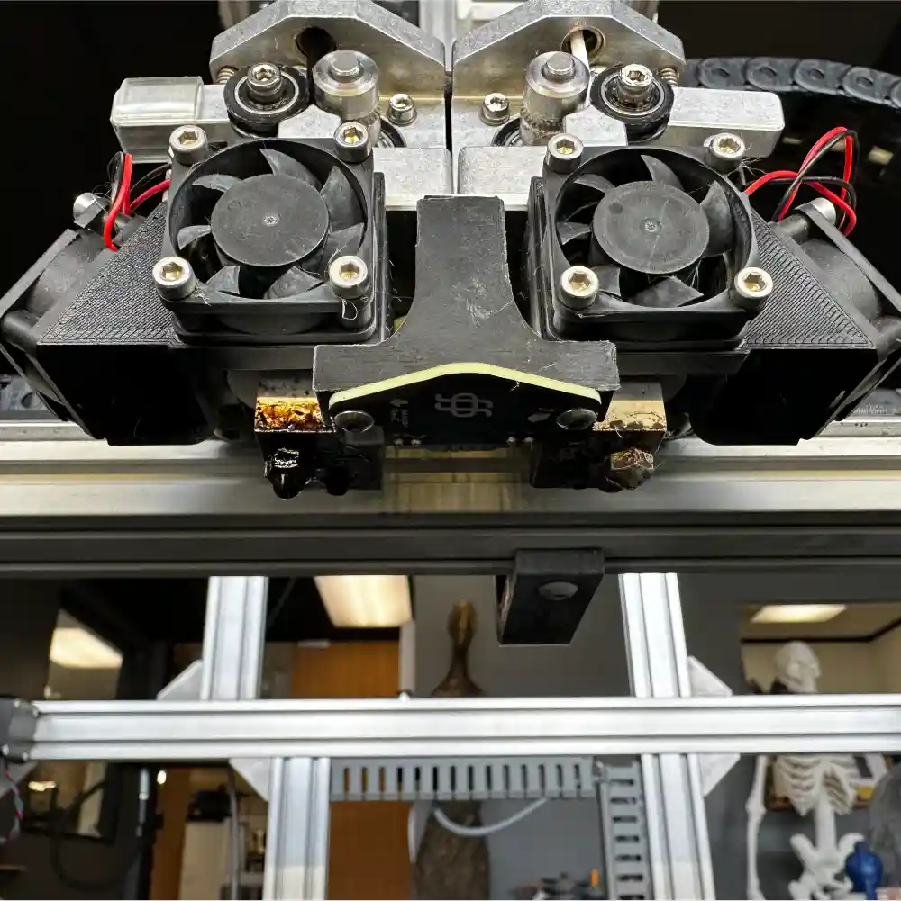
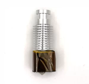
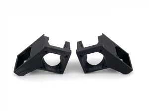
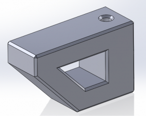
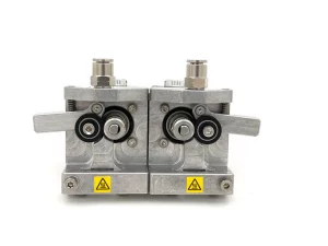
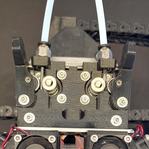
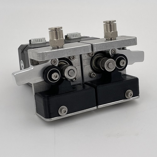
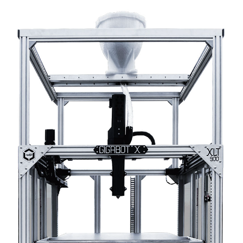
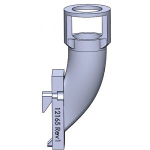
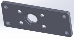
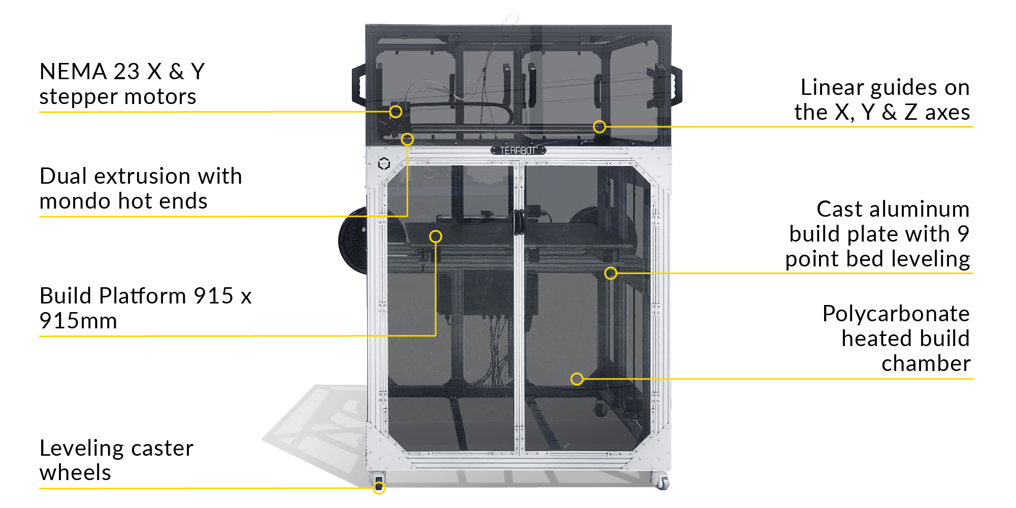
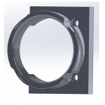
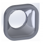
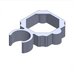
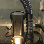
re:3D has a long history of designing and testing extruders and hot ends, always looking for ways to push more plastic to print faster. (OG members of the re:3D community might remember the early “Mondo” hot end prototype.) To keep up with its larger build volume (915 x 915 x 1000mm), re:3D’s Terabot filament printers have been shipping with “20 Series” hot ends, which have a larger heater block to increase the residence time of the plastic within the heat zone and speed the melting process (Figure 3). However, testing has shown that with the proper slicer and configuration settings, re:3D’s standard hot ends perform equally well and are less prone to occasional inconsistent flow or leaking at the nozzle.
To improve overall performance and reliability, Terabots will now be supplied with standard hot ends. This is a minor engineering change, and the Customer Service team has developed a simple and easy-to-install upgrade kit that requires no major modifications to existing Terabot platforms. The Customer Service team is looking for initial Beta Testers for the Terabot hot end conversion kits. If you are interested, you can read more about re:3D’s Beta Testing Program below.
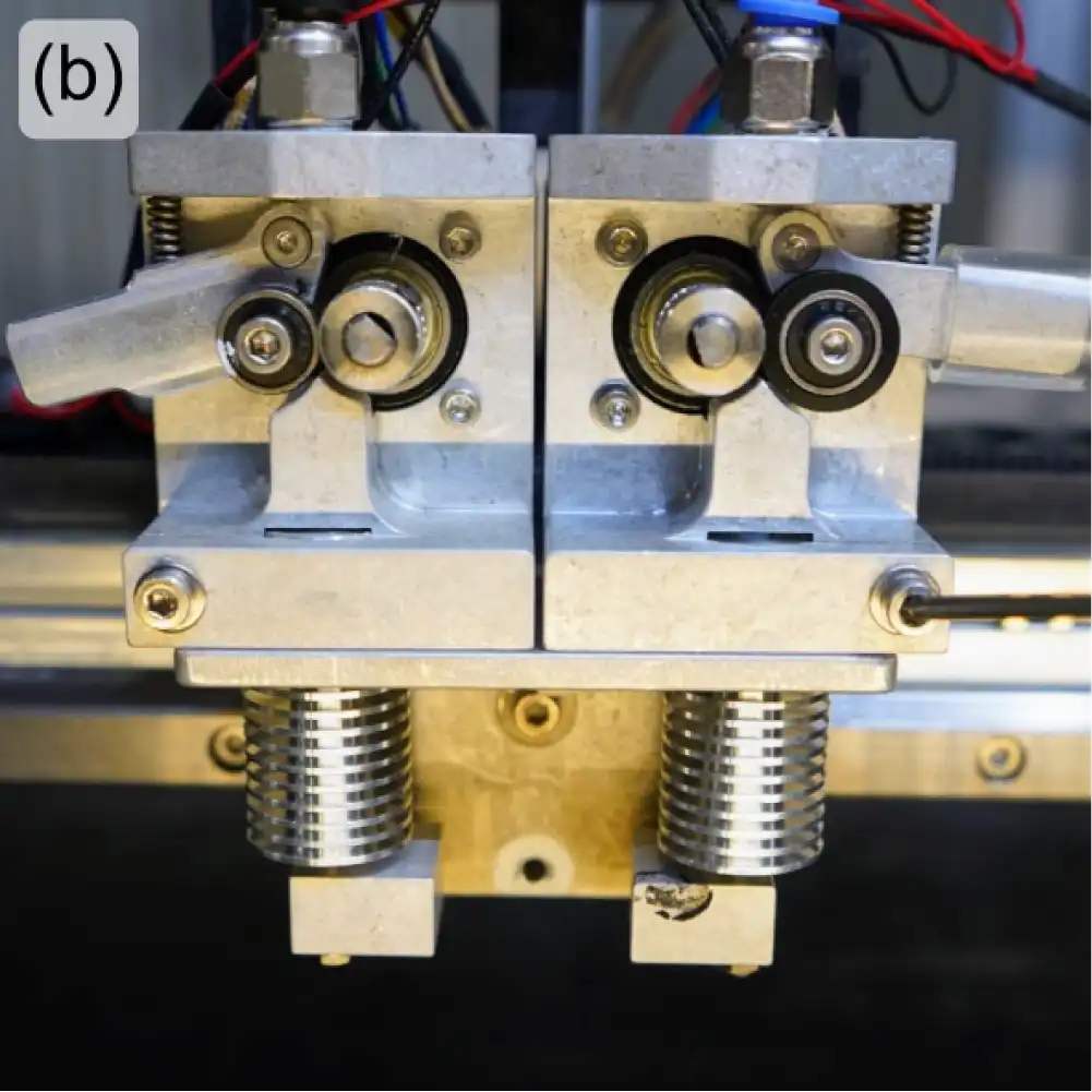
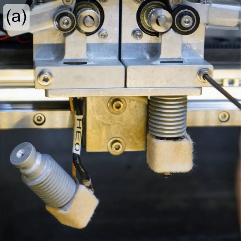
Figure 3: Comparison of 20 Series hot ends (a) and standard hot ends (b) installed on a Terabot.
The GigabotX FGF (Pellet) Platform
There has been progress on both GBX part cooling and GBX bed mesh compensation, but the Gigaboss leading those efforts is busy finishing his master’s thesis, so you’ll have to hold off until next time for a written update. Do worry – it’ll be worth the wait.
Software Improvements
re:Bugger
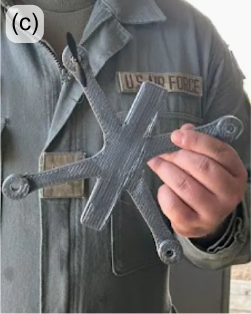
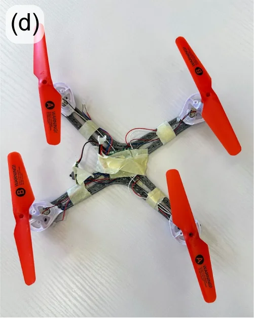
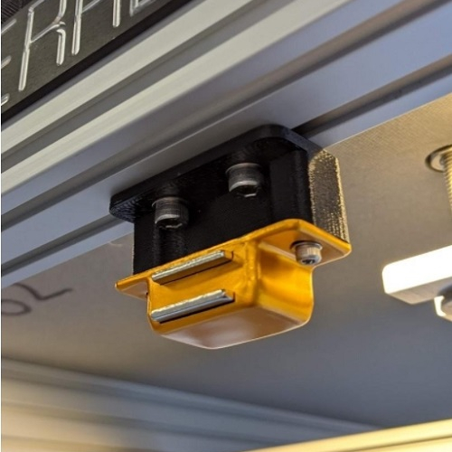
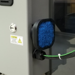
This spring semester, re:3D has been pleased to host Yasseen Hilal, who is studying computer science at the University of Texas, as a software engineering intern. Yasseen took on the task of developing a printer debugging tool for use in the field. The re:Bugger (Figure 4) simply plugs into a Gigabot 4, Terabot 4 or GigabotX 2 via a network cable, then through a simple and intuitive interface reads the available log files to detect errors and provide possible solutions. Log files and performance graphs can be easily exported from the printer onto a USB drive for later review, and the re:Bugger also allows users to flash the latest printer firmware onto the Raspberry Pi without needing network access. This all helps reduce printer downtime.
Yasseen did a great job on his project, and the re:3D team wishes him all the best on his future endeavours.

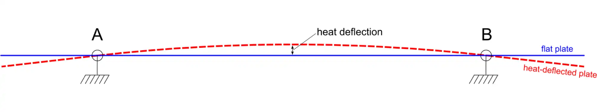
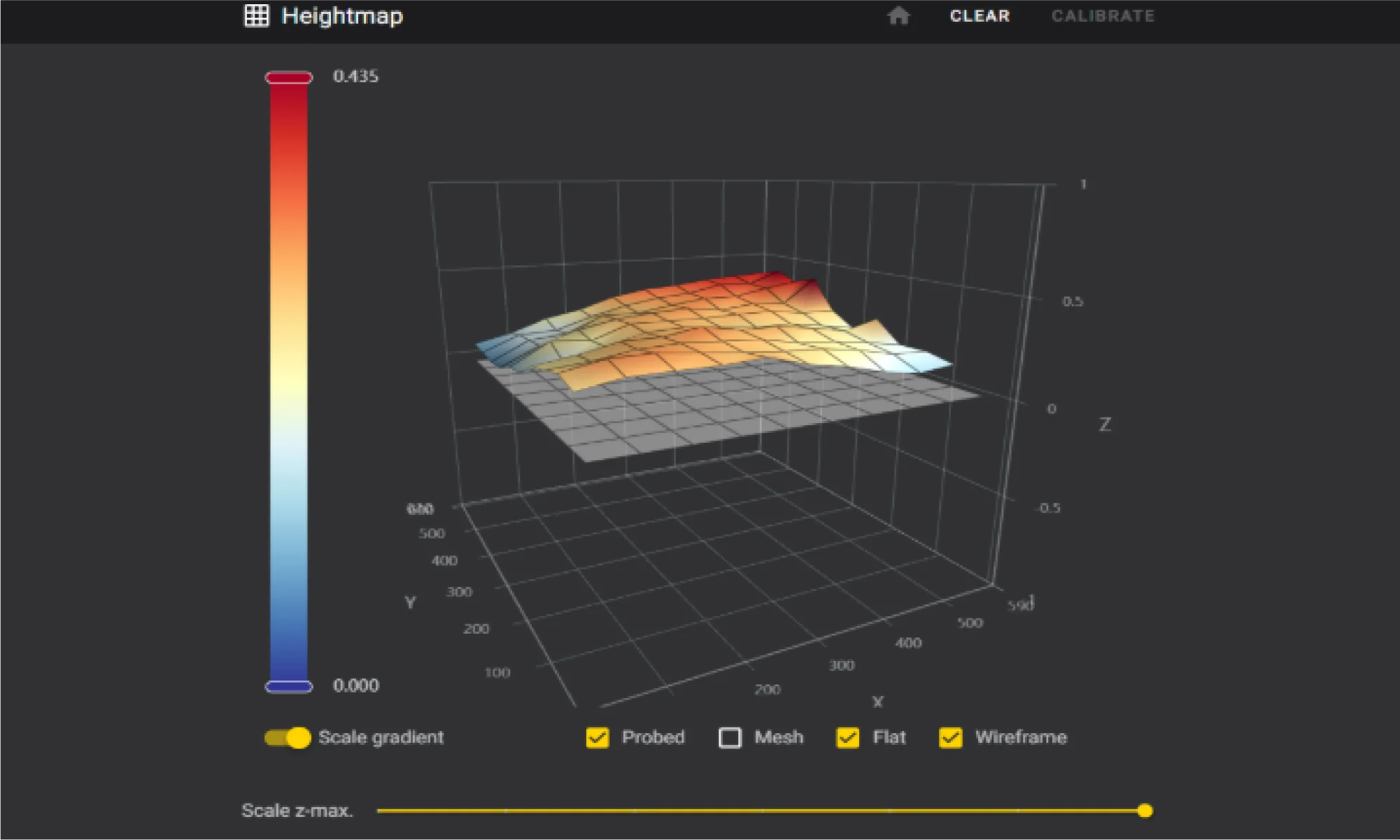
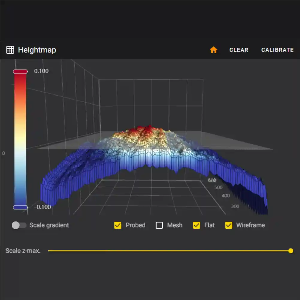
Bed Mesh Compensation
There was recent feedback on accuracy and standard operation being manually intensive. Updates have since been made on the mesh compensation workflow which will now carry out a startup procedure to automatically calibrate the Z offset, tram the Z lead screws, and adaptively probe only the area where the part is printing.
This new workflow is meant to keep manual efforts to a minimum during calibration. This procedure is written into Klipper as a comprehensive macro and can be called at the beginning of a print using a single line of Gcode in the slicer.
This master macro approach makes usage simple for the end user while also ensuring accurate and standardized results. There are also optional advanced parameters for users who want to fine tune and experiment with values.
- Procedures:
- Prime the extruder
- Clean the nozzle for accurate offset calibration and probing
- Model calibration
- Z offset Calibration
- Z tilt calibration
- Adaptive probing
We are actively seeking feedback through our beta testing program, and encourage new testers to contribute their insights to further refine and improve this workflow. You can learn more about re:3D’s Beat Tester Program below.
HELM
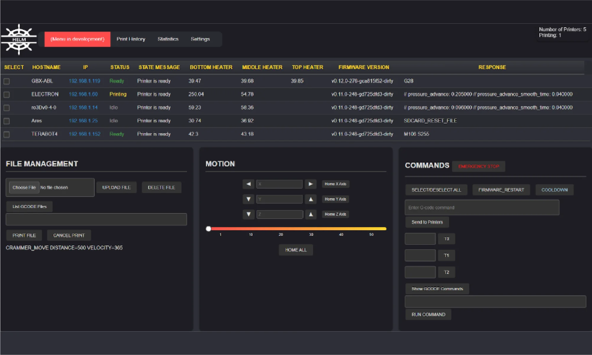
Work also continues on HELM, the printer fleet management software under development at re:3D. There have been some minor changes under the hood since the last update, but the most obvious improvement is the user interface – it’s cleaner and easier for casual operators to use (Figure 5). This is an open-source project, and you can try the application yourself, report problems, contribute, or follow progress here: Helm on GitHub.
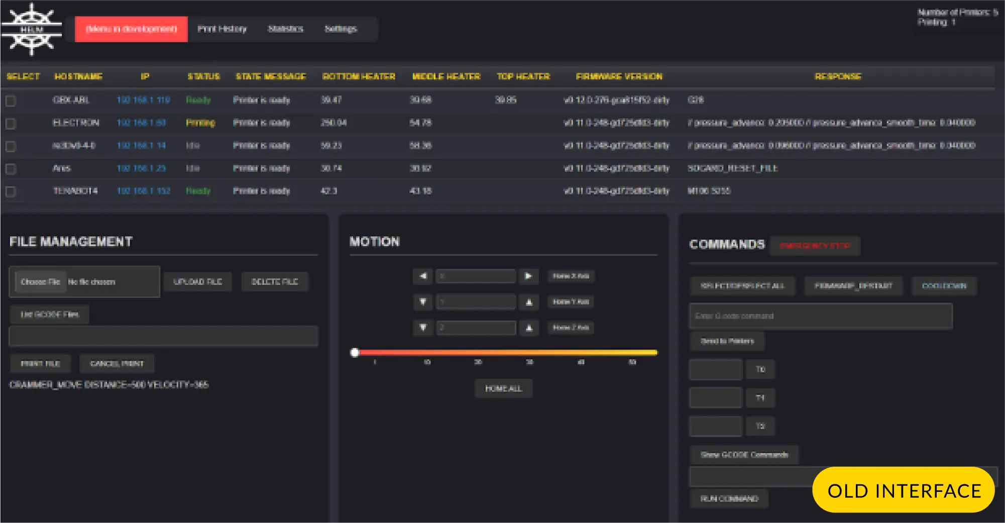
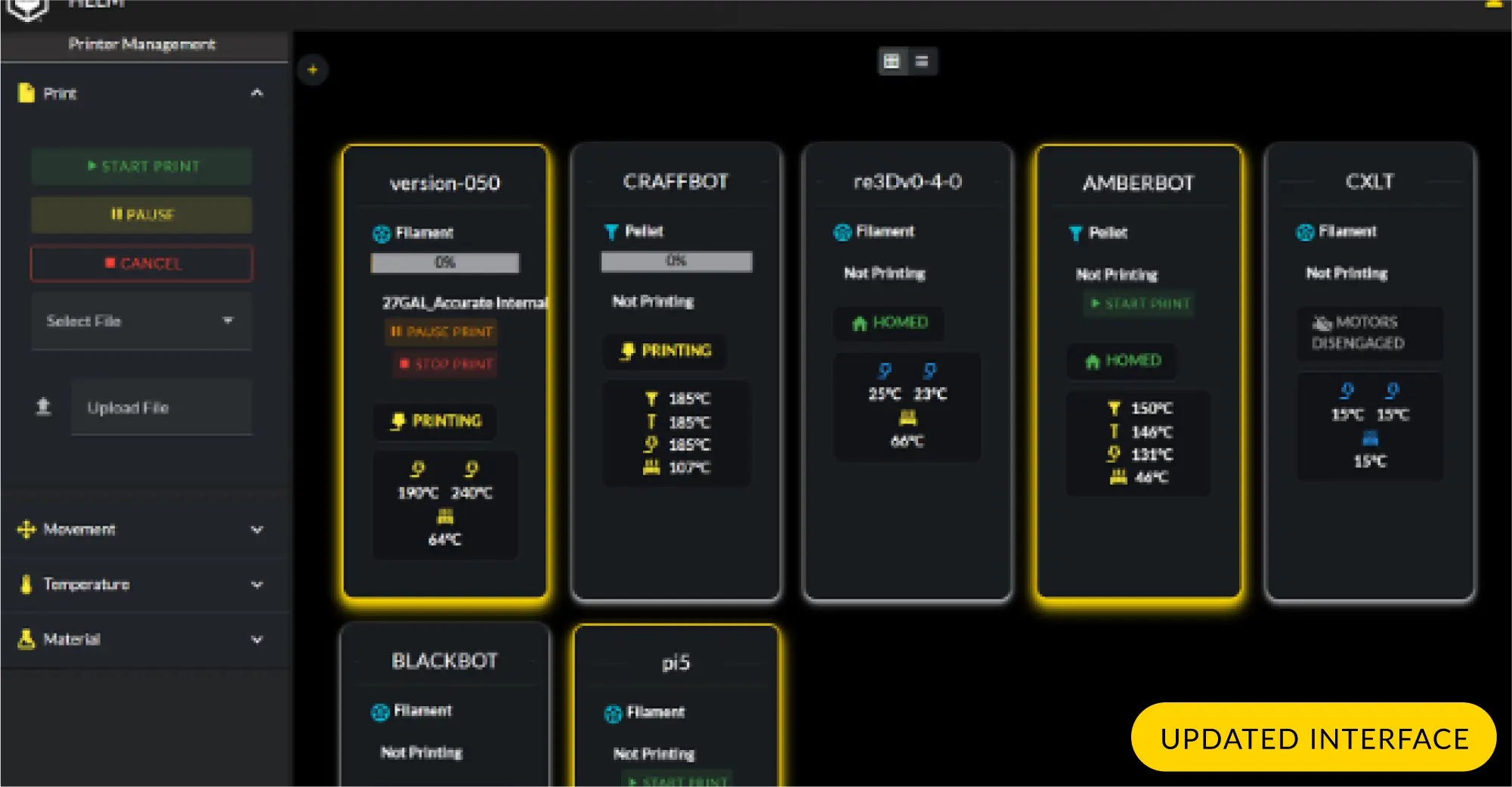
Figure 5: Comparison of the HELM GUIs - older version on top, updated version on bottom.
Beta Testing Programs
As an open source company, re:3D celebrates collaboration with our community of users, customers and vendors. Historically, select new changes or features were offered to existing customers for ‘beta testing’ as part of re:3D’s internal engineering process. The Beta Testing Program has since evolved and become more formalized with contributions from engineering, customer service and sales and marketing. An application form is now available on the re:3D website here where you can apply to be a beta tester through the following steps:
1. Choose Your Desired Beta Product/Software
Read a short summary of available beta products with how it will improve the Gigabot user experience. Ideally, applicants will have non-modified printers so that the performance improvements of the beta products can be accurately assessed.
2. Sign Up
Fill out a Google Form to express your interest in beta testing the selected product for which you’d like to be considered.
3. Confirm Acceptance
A notification email will be sent to confirm your selection as a beta tester. This will include a beta tester release agreement, a defined testing period, steps on how to submit feedback, and a link to the Forum for updates on these products. Invoicing and delivery information will also be requested, then the beta products will be shipped.
4. Begin Testing
An Instructional Guide with detailed installation instructions and troubleshooting tips will be provided with the beta products.
A Google Form will be sent to beta testers no less than monthly for each product to solicit feedback and recommendations.
5. Be a proud GigaTester!
For now, there are two beta test products available for consideration:
- Bed Mesh Compensation (Gigabot 4 only)
- Terabot Hot End Conversion (Terabot family)
Watch for these additional beta testing opportunities in the coming weeks:
- Bed Mesh Compensation (GigabotX 2 only)
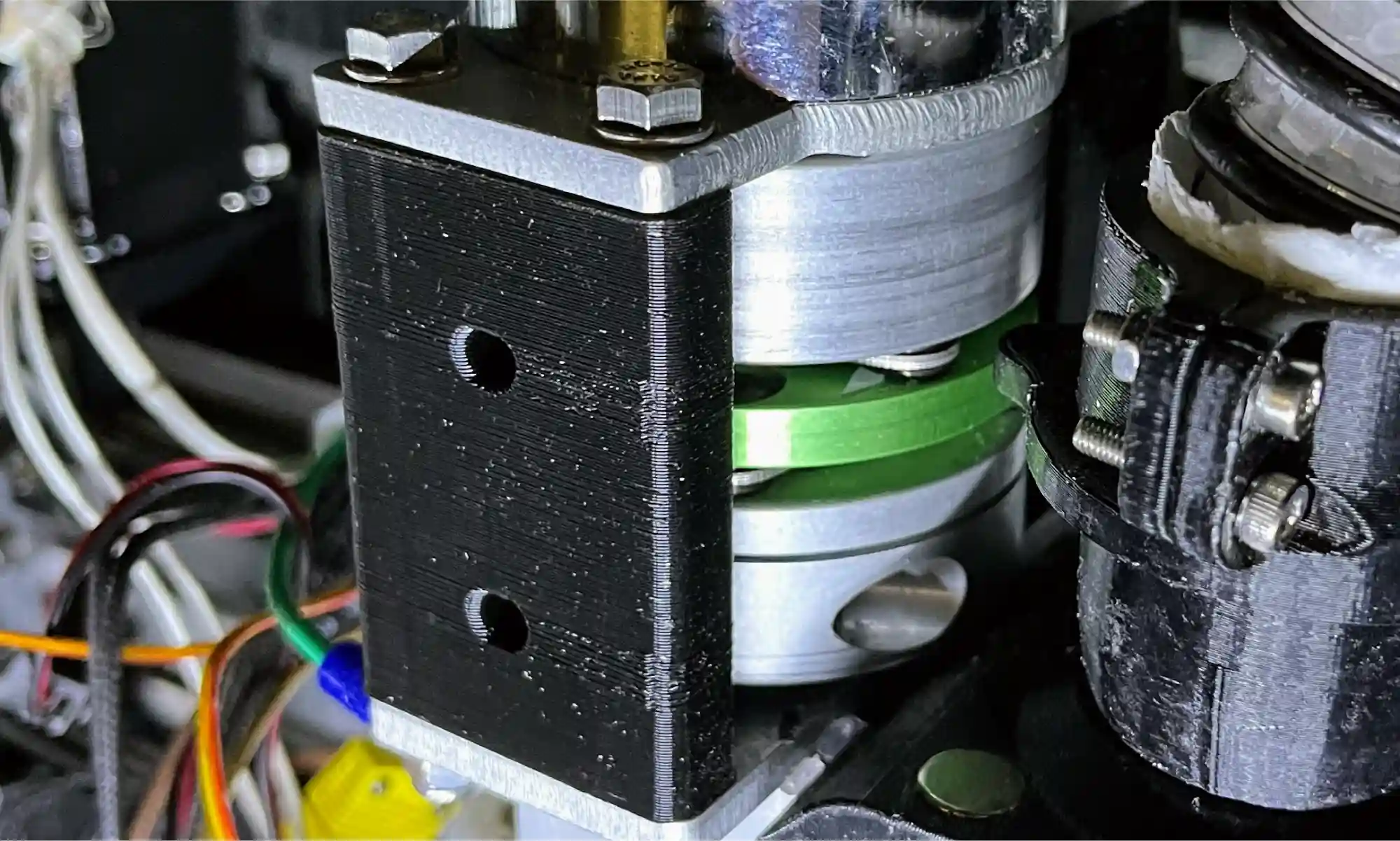
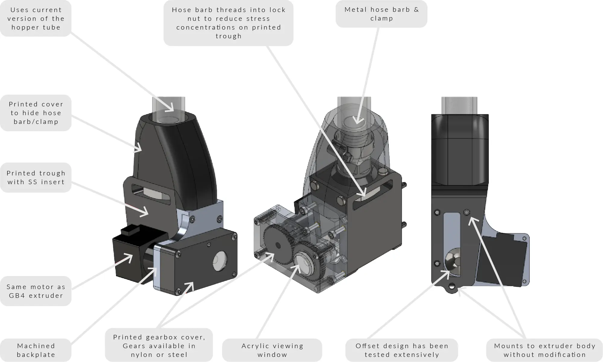
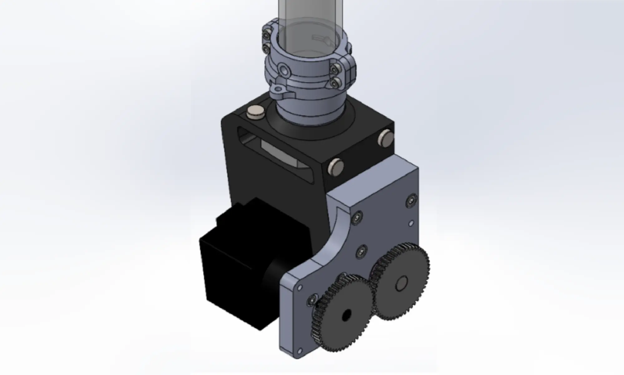
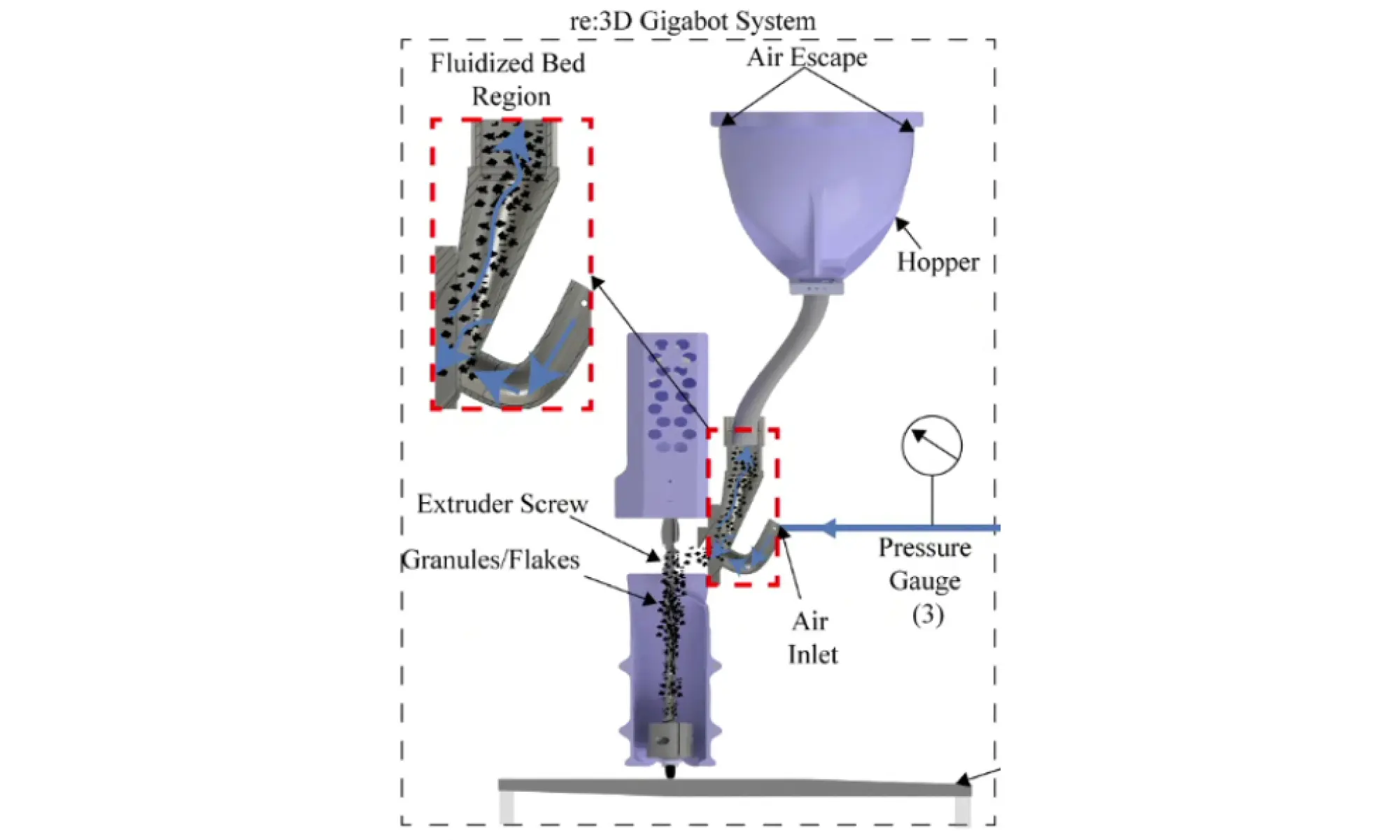
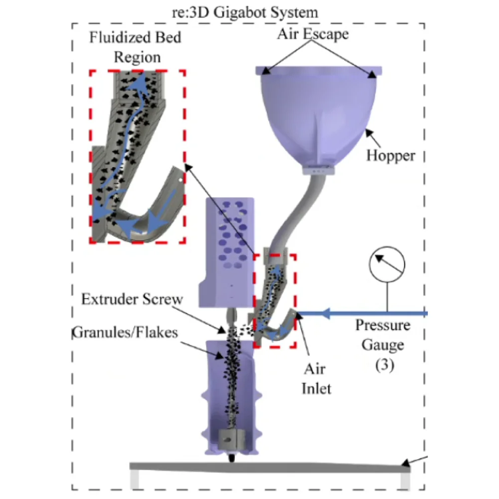
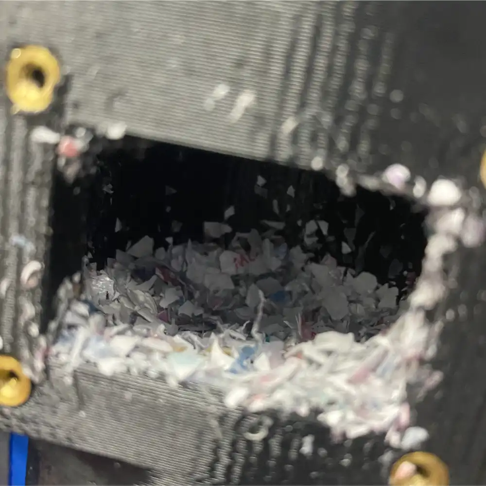
- Feedstock Crammer (GigabotX family)
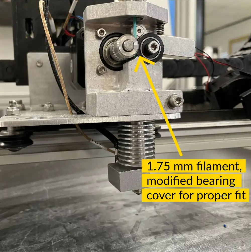
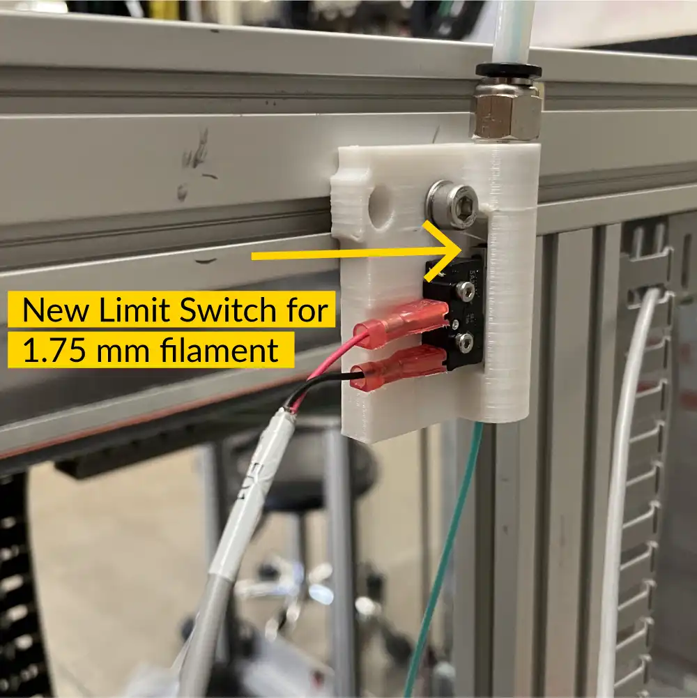
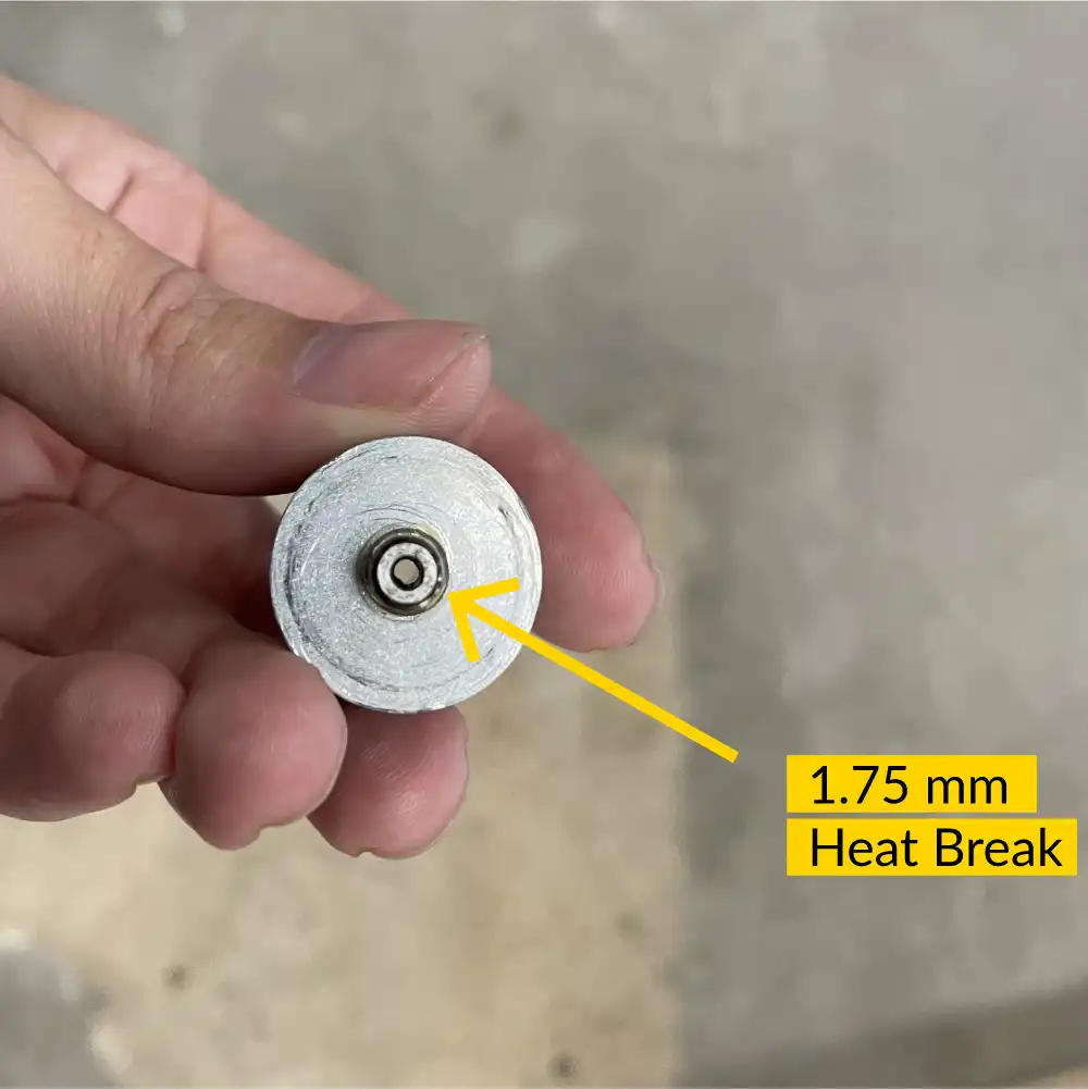
- 1.75mm Filament Conversion Kit (Gigabot / Terabot family)
- GBX Part Cooling (GigabotX family)
R&D Programs
Though there has been recent turmoil and uncertainty in the news about federal research grants, re:3D continues to support R&D contracts for the Department of Defense (DOD), NASA, the Department of Energy (DOE) and the National Science Foundation (NSF). Some of those projects went along on re:3D’s recent trip to Hawai’i, but the others have been making progress too!
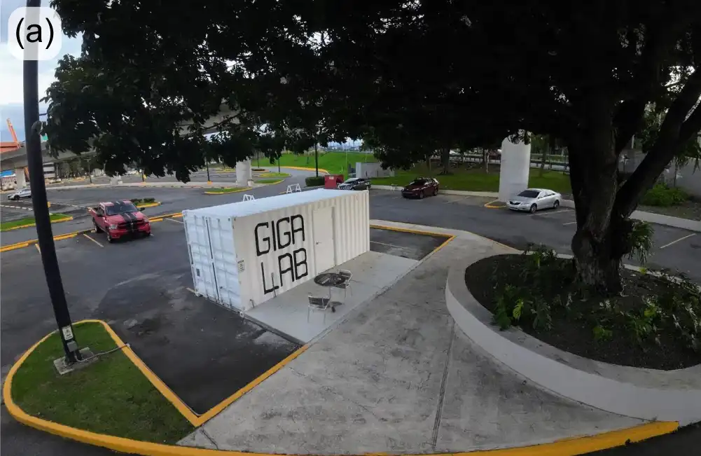
ReCreateIt (NSF)
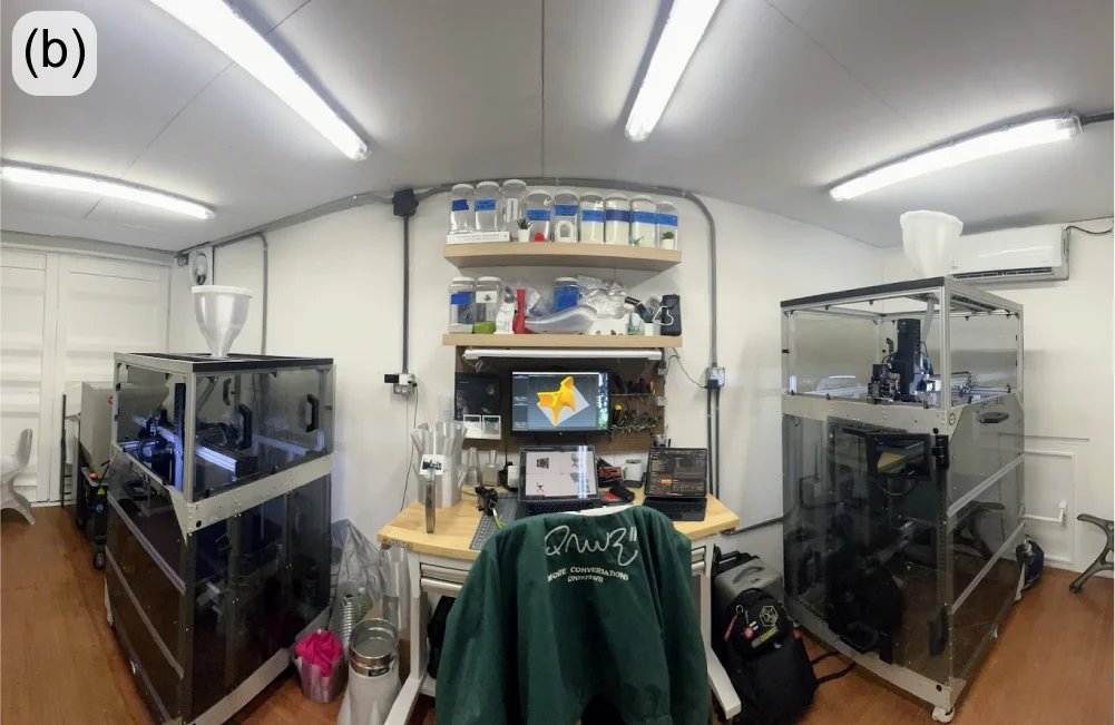
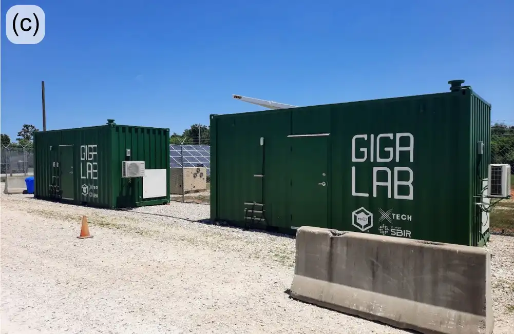
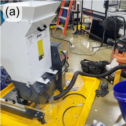
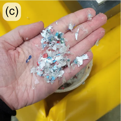
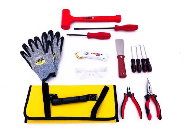
ReCreateIt is a multinational initiative led by re:3D, with a goal to transform waste plastic into valuable products through 3D-printing and community-led design. To achieve this mission, re:3D is collaborating with the Austin Habitat for Humanity ReStore, where a Gigalab was designed and delivered in December 2024. Since its delivery, the Gigalab has been outfitted with a granulator, pellet/flake dryer, a GBX2 XLT, all necessary mechanical and electrical tools, and personal protective equipment. The long-term goals of the ReCreateIt Gigalab is to recycle and reuse over 10,000 lbs of local plastic waste over its lifetime while being a net-zero energy manufacturing lab.
Compared to other Gigalabs, the ReCreateIt Gigalab will feature various additional sensors that monitor temperature, humidity, emissions, particulate matter, and energy usage. The sensors will allow the team to construct a comprehensive model of the Gigalab system and quantitatively assess the environmental impact of the Gigalab and the recycling efforts. This data may also provide the re:3D team with insights that may spur redesigns and improvements of future Gigalabs towards more energy-efficient and sustainable systems.
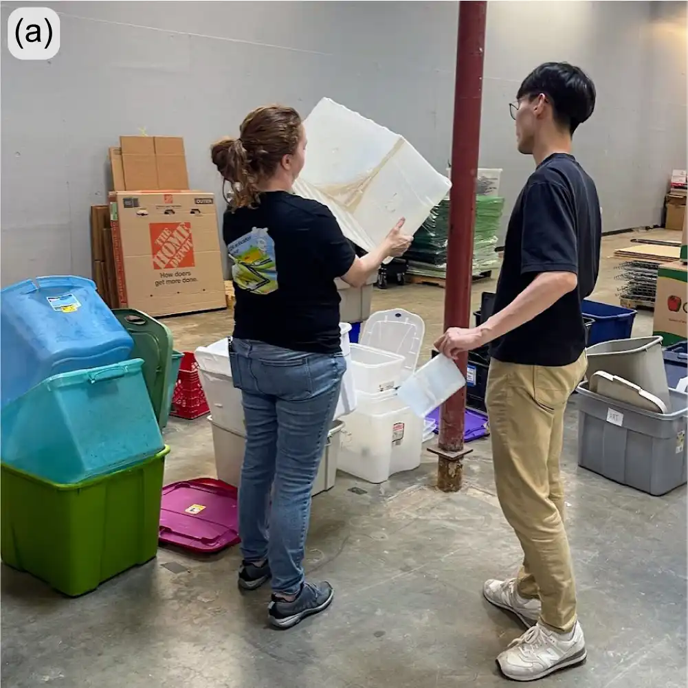
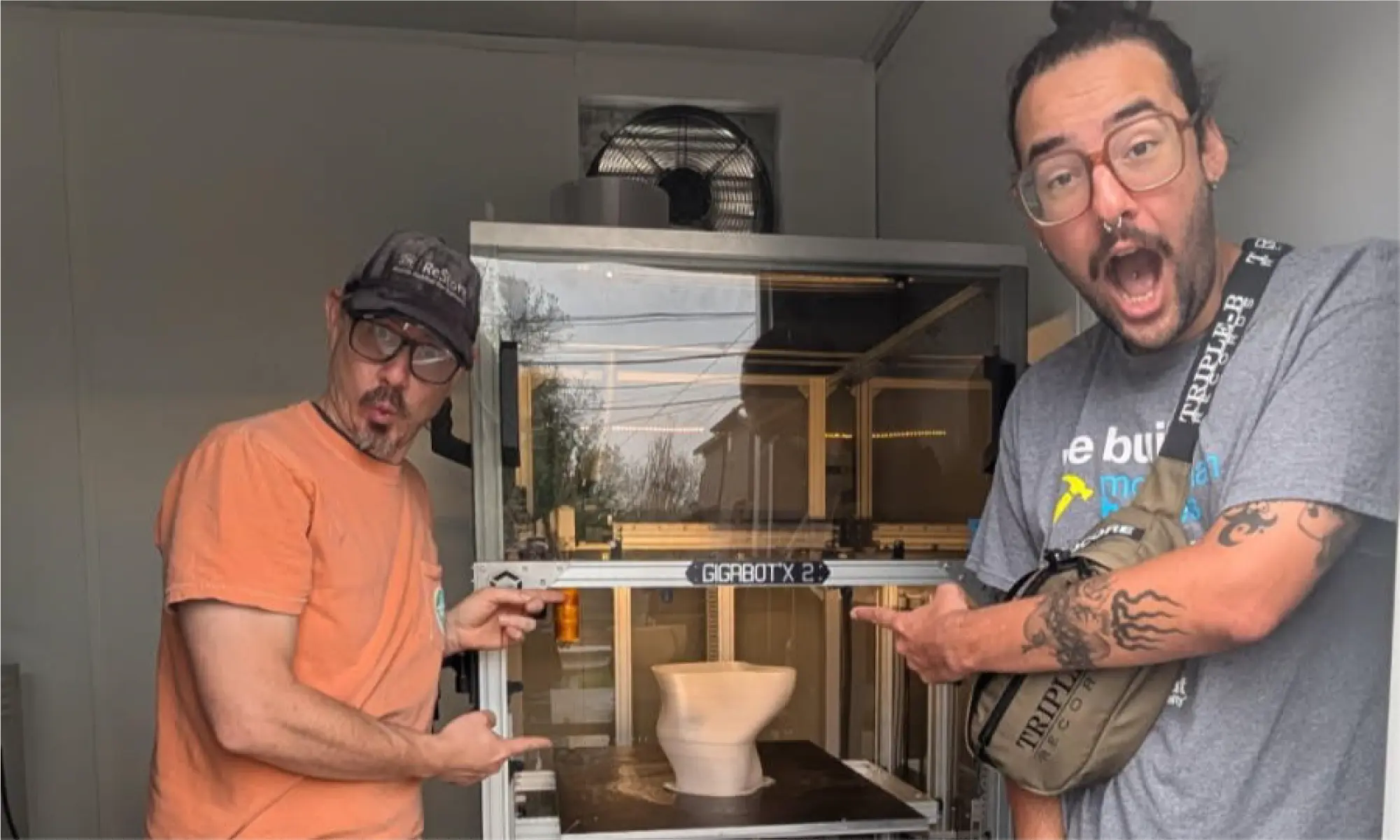
To support daily operations, three Gigalab associates have joined the team to collect and sort incoming waste plastics, and to operate the machinery that processes and prints with the recycled materials. The re:3D team is actively mentoring the associates to enable them to operate and troubleshoot the Gigalab equipment safely and autonomously (Figure 6).
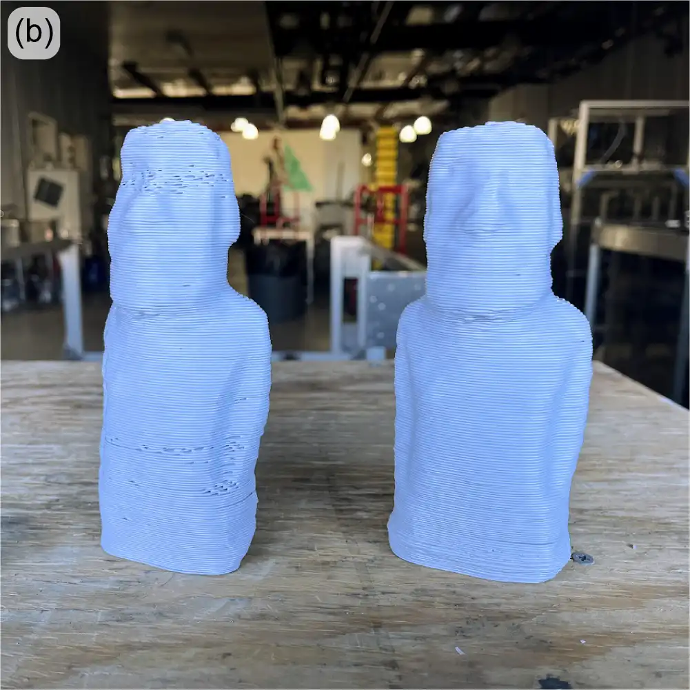
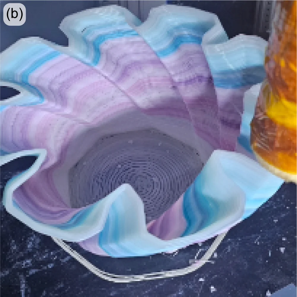
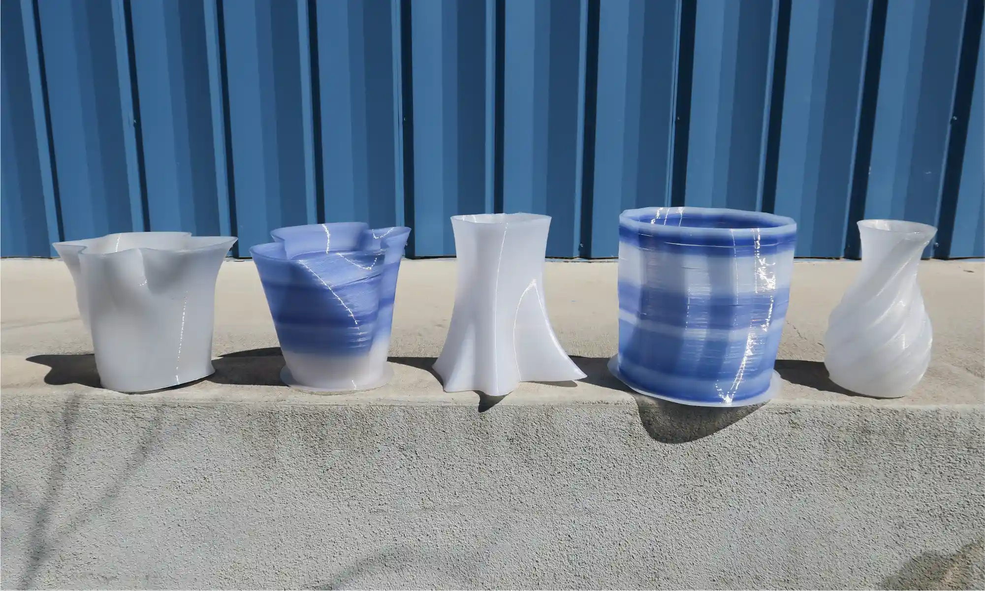
There have also been advancements in 3D printing with recycled polypropylene (PP) — the second most used commodity plastic in the world. In fact, the vases shown in Figure 7 below are printed from 100% recycled PP, which were originally storage bins collected at the ReStore that were destined for the landfill. While there still are challenges to scale up into furniture pieces such as end tables or stools, achieving successful and functional parts using 100% recycled material, without any additives or blending agents, is a significant milestone in sustainable manufacturing.
To showcase the progress on the project to the public and local media, the ReStore and re:3D teams co-hosted a soft opening at the ReStore on April 19. Well over a hundred curious customers stopped by to take a look at a large array of printed parts made from recycled materials. Attendees were invited to share their ideas for future products, offer feedback on existing prints, and learn more about the environmental and social impact of the initiative. The majority of visitors also expressed major interest in the behind-the-scenes of the project and participated in tours of the Gigalab, where they got a first hand look at the recycling and manufacturing process including the GBX2 in motion.

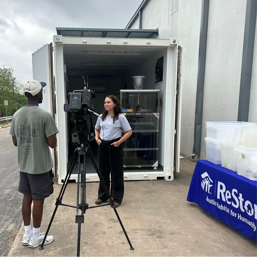
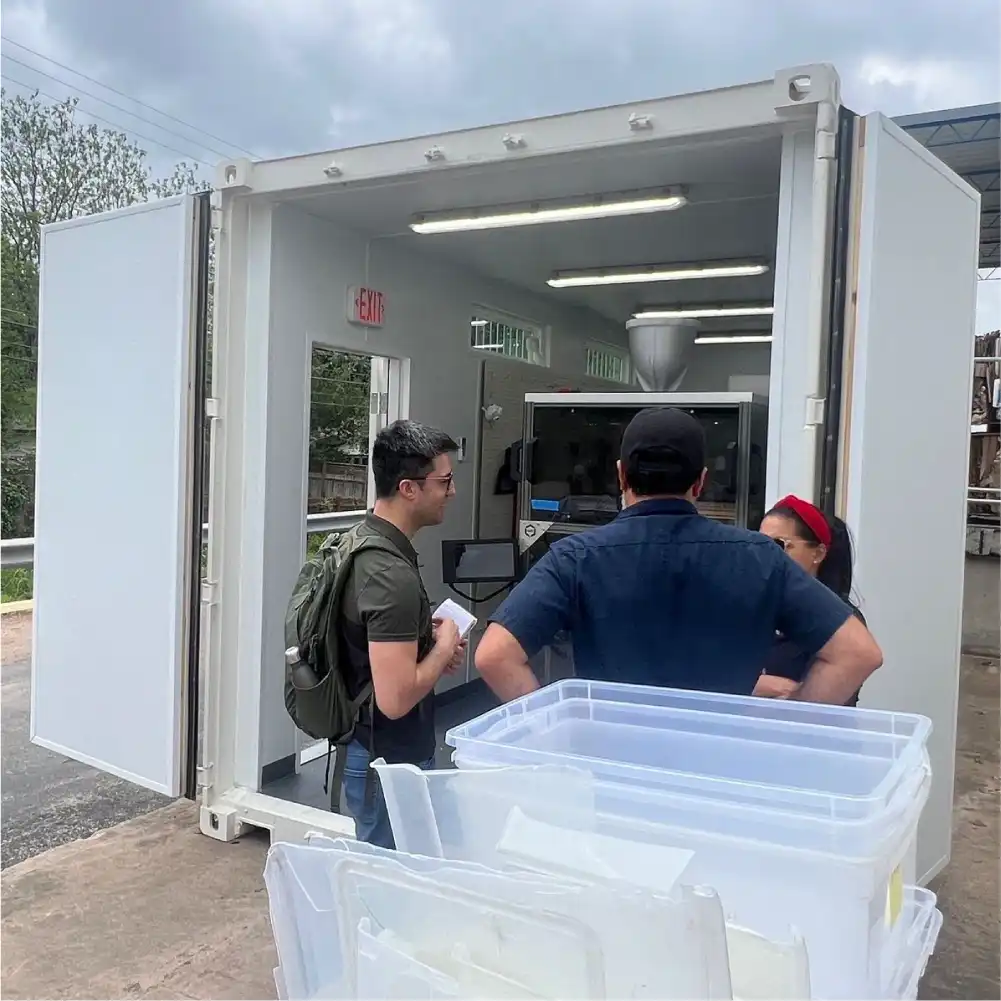
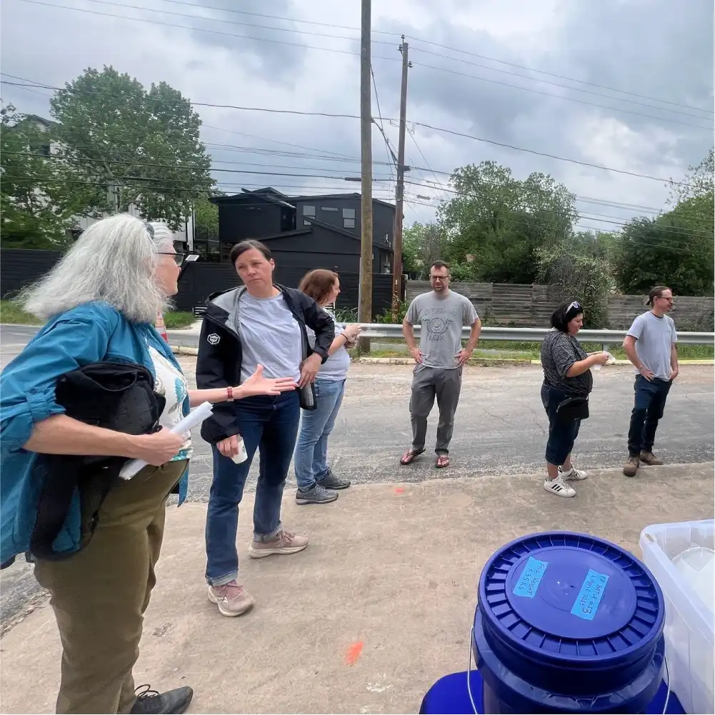
Figure 8: ReCreateIt Soft Opening at the AHFH ReStore.
If you’re in the Austin area, stop by the ReStore at 500 W. Ben White Blvd where you can check out the prints in person, buy a piece printed from recycled waste and directly participate in the circular economy yourself.
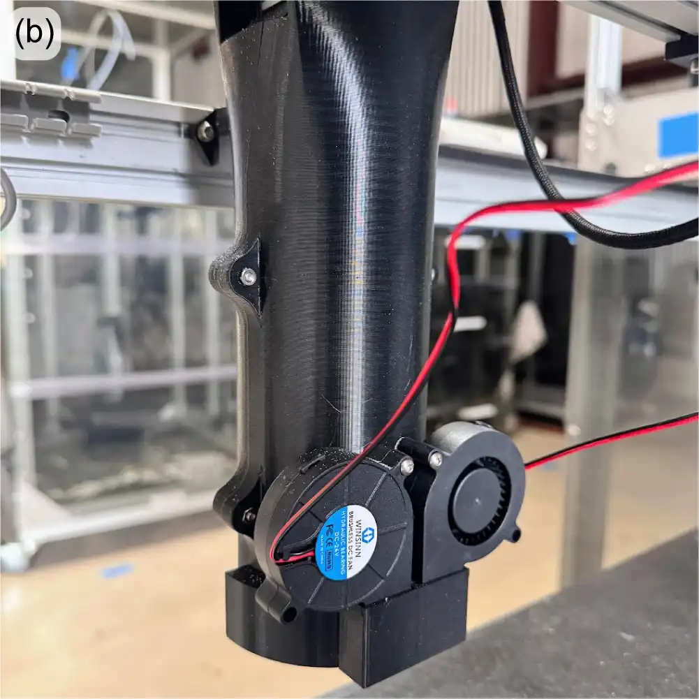
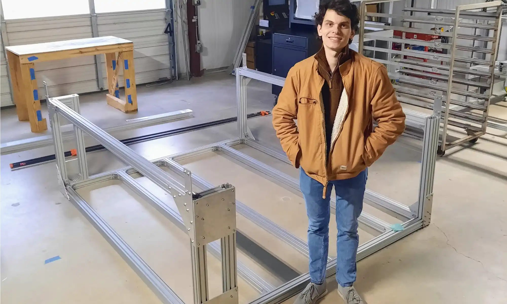
“Bigger, Better, Faster” FGF (DOD/US Army)
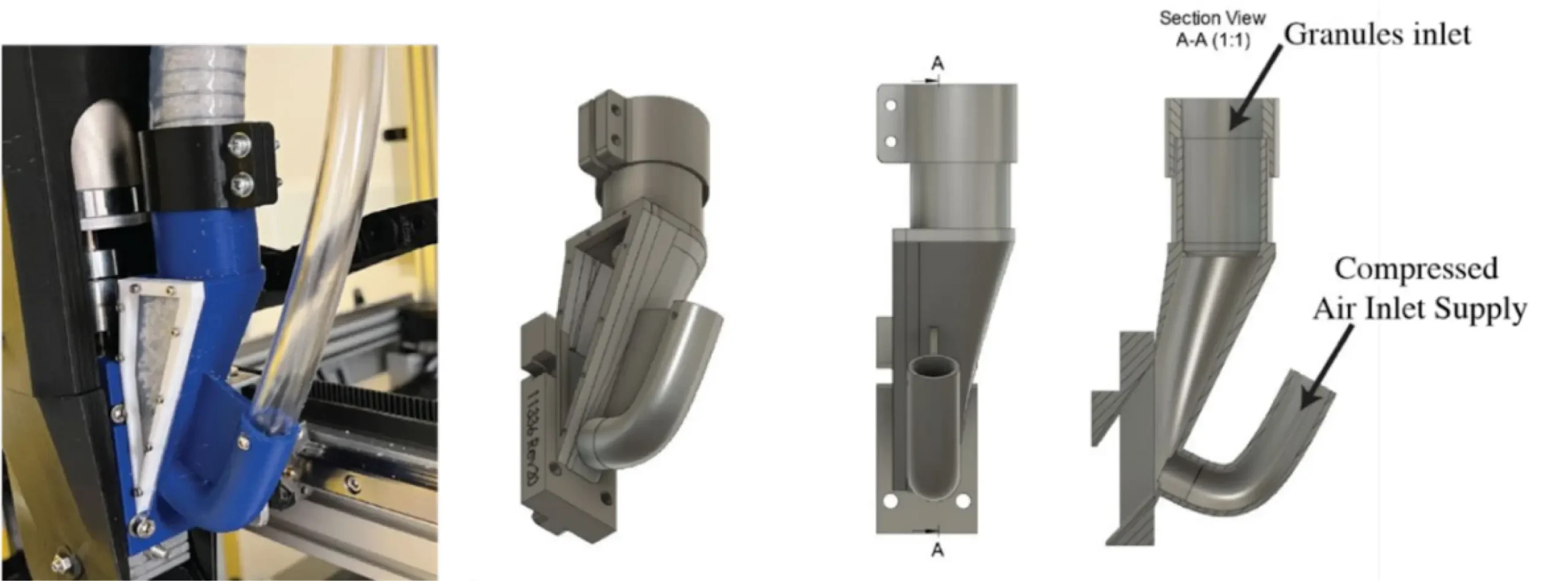
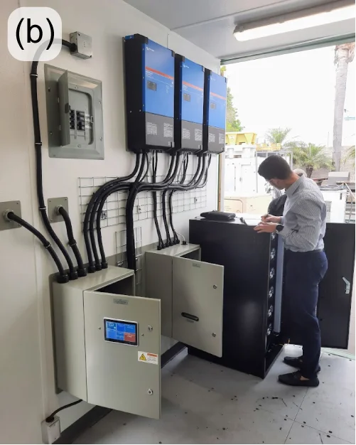
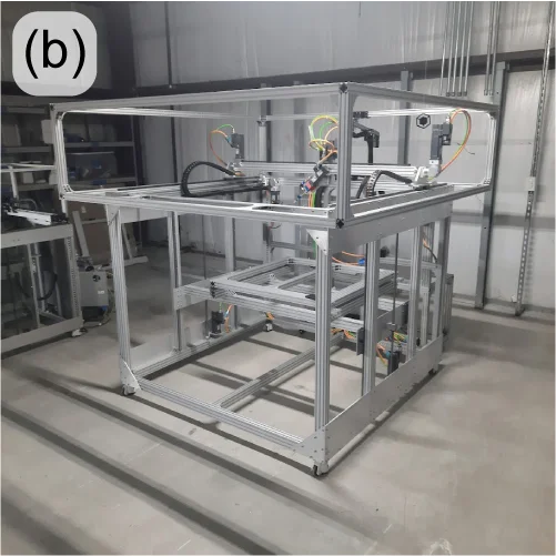
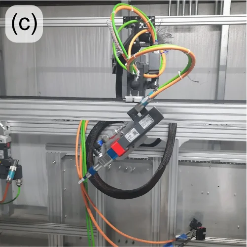
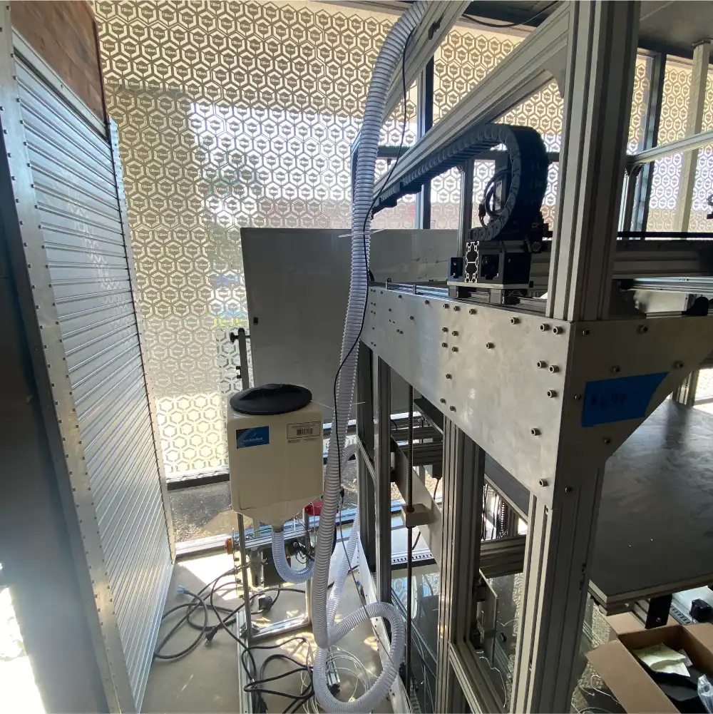
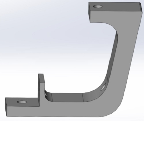
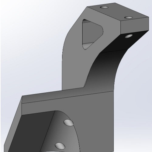
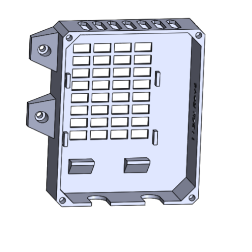
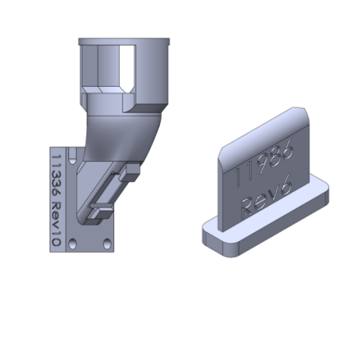
The large FGF printer being developed under a US Army SBIR R&D award has come a long way since the last update. The frame is complete, and the linear motion components – including ball screw actuators and servo motors – are installed and commissioned (Figure 9(a&b)). Another major change from re:3D’s traditional build style is the use of a separate HMI (human-machine interface) and control pedestal (Figure 9(a&c)), rather than having an electrical box and touchscreen interface mounted directly to the printer’s frame. Not only does this change allow for the room needed for added servo motor controllers and power supplies, it makes the electrical and control components more accessible for service. Having a full computer built into the HMI pedestal will allow users to access third-party software when necessary for servo motor diagnostics, along with providing opportunities for performing CAD and slicing tasks at the same workstation as the printer operation, without requiring network access – which is not available or desirable in some situations.
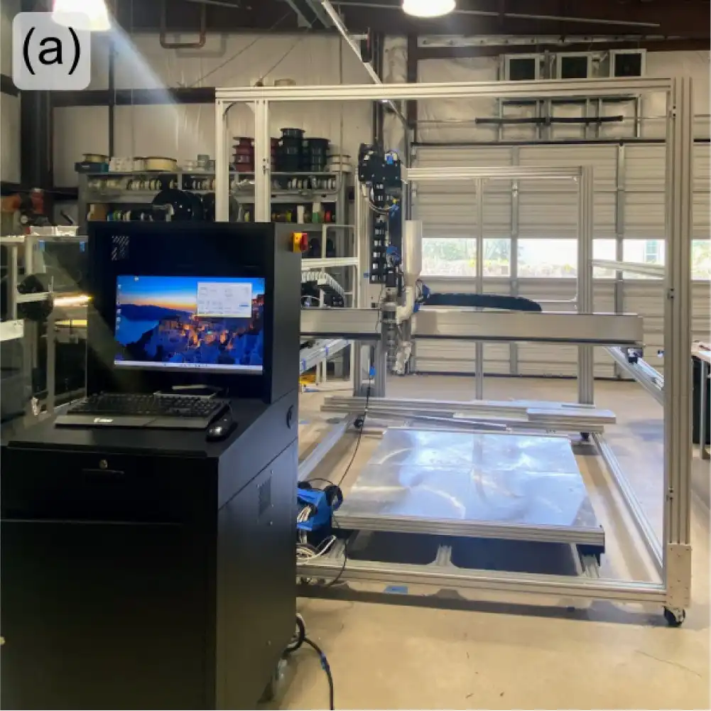
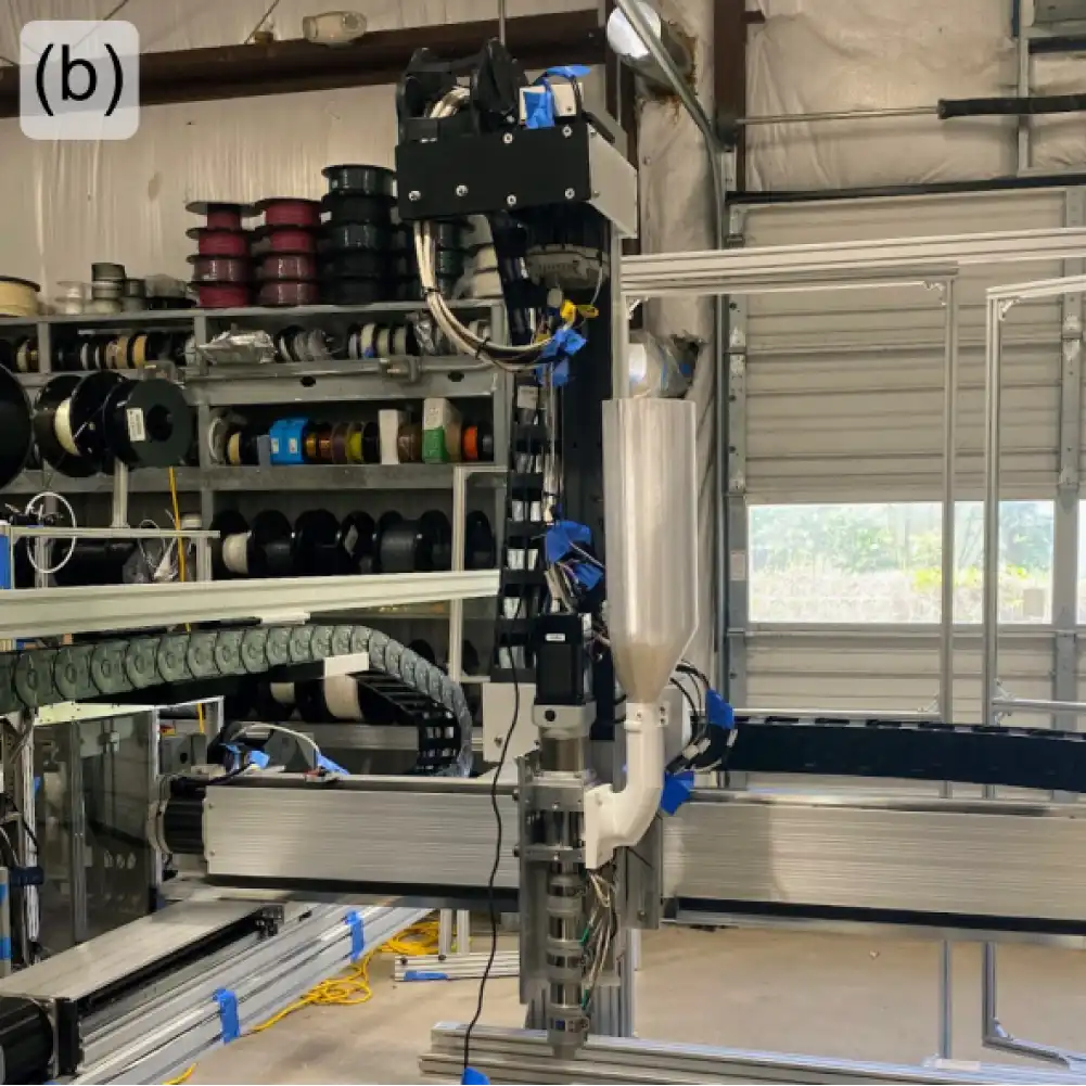
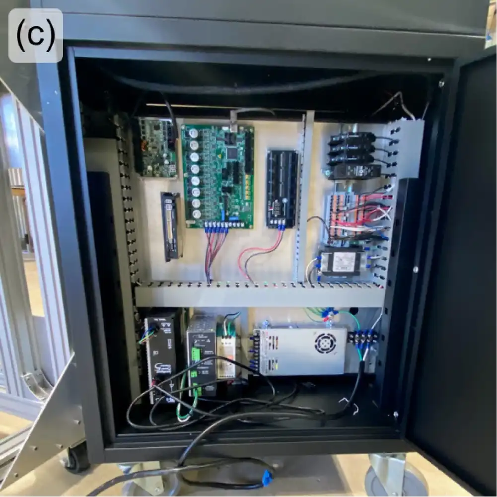
Figure 9: Printer frame with HMI/control pedestal (a); extruder mounted on z-axis actuator with temporary side hopper (b); inside view of HMI/control pedestal during initial wiring (c).
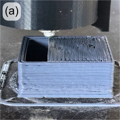
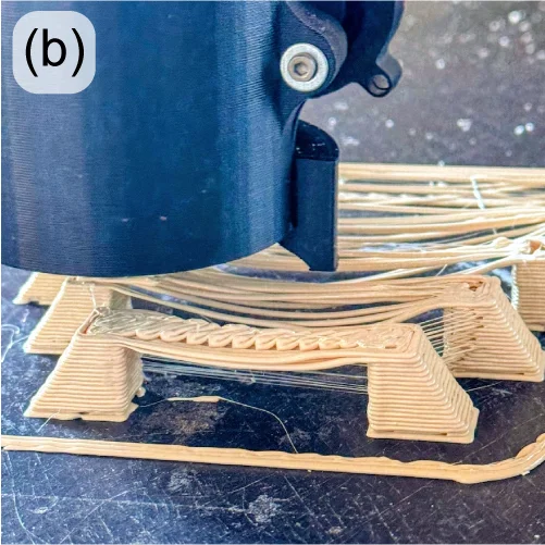
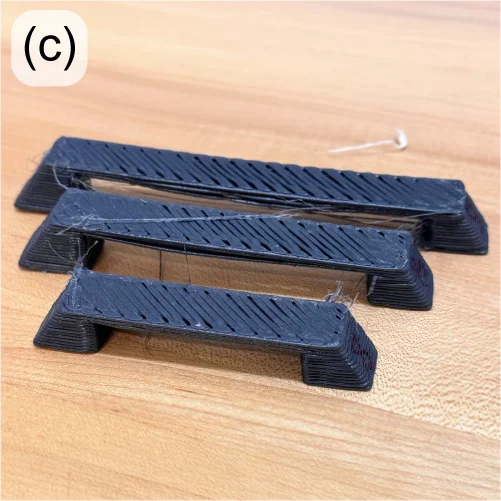
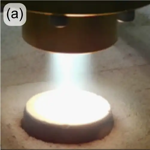
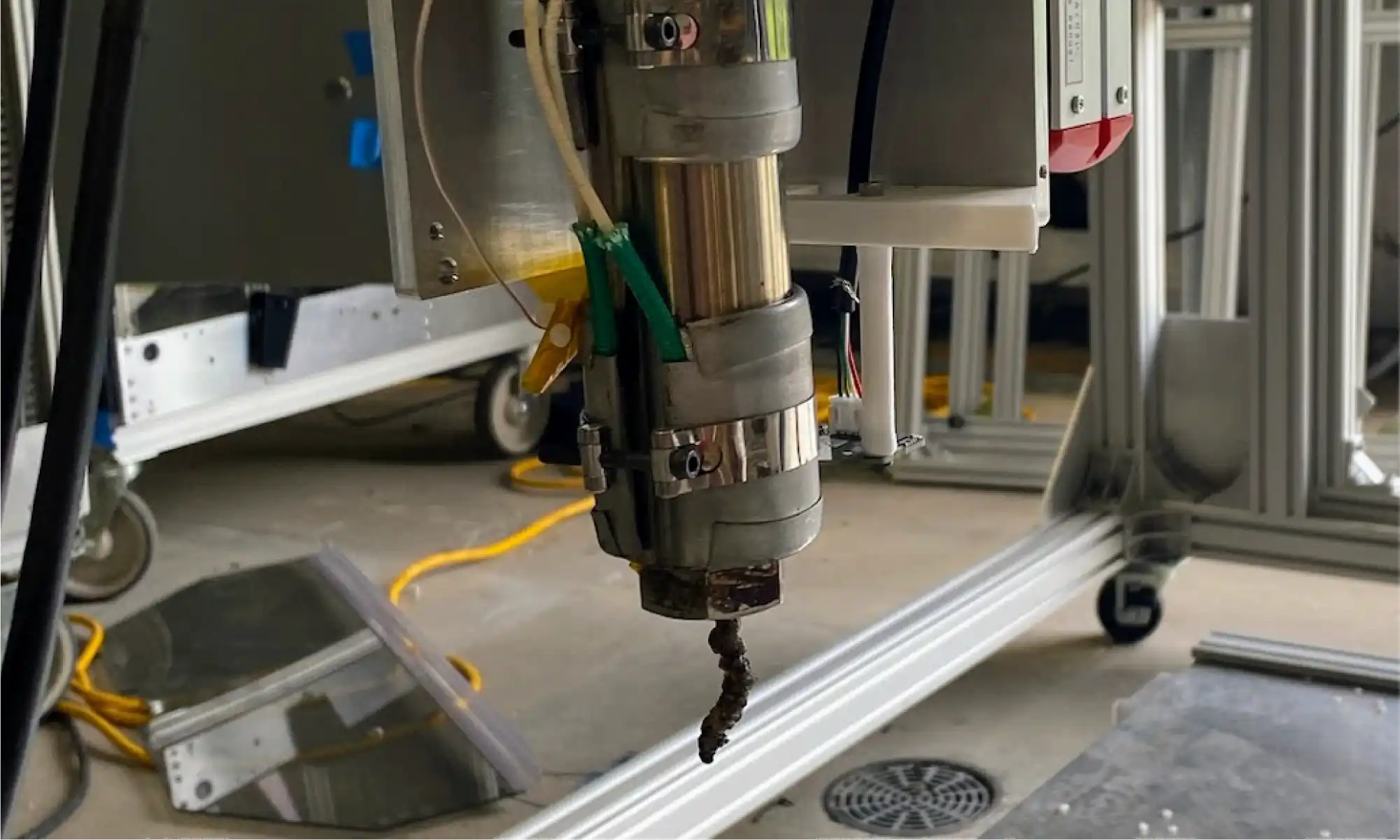
After commissioning and initial tuning, the printer’s extruder was finally tested. This is a novel and exciting new design from Dr. David Kazmer’s group at the University of Massachusetts Lowell, who are collaborating with re:3D on this effort. After a few hiccups caused PLA to thermally degrade inside the barrel, DynaPurge became the first material extruded through this system. As shown in Figure 10, the first extrusion looks like – well, you know. But it’s a first extrusion nonetheless, and the team is excited for the rapid progress of this project.
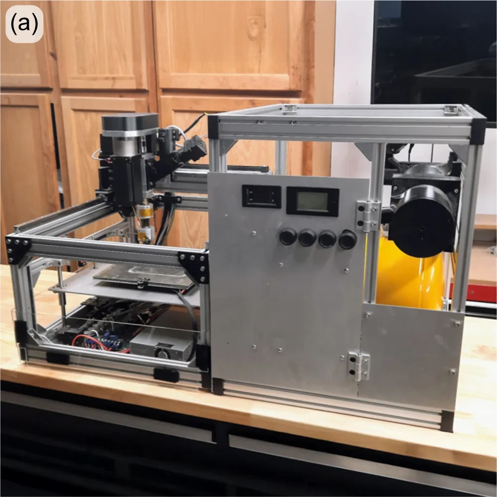
Additively Manufactured Thermal Protection Systems (NASA)
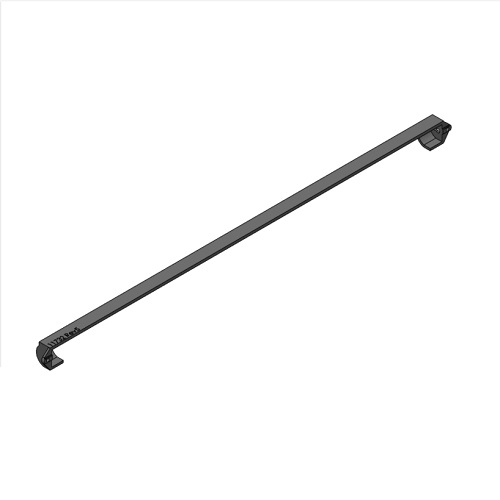
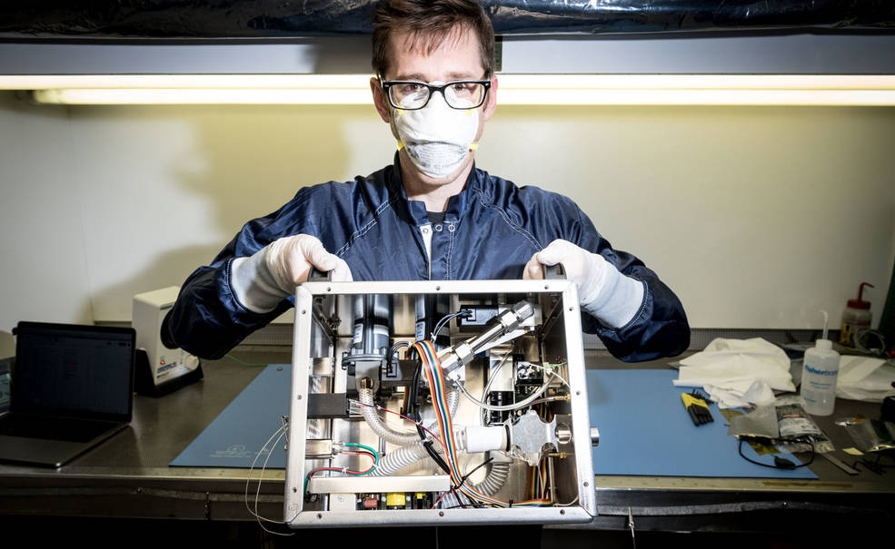
re:3D’s R&D team designed and built a 5-axis printer to deposit ablative foam materials onto non-planar surfaces. This has been done before using robotic arms, but this is a unique design based on a gantry system, intended to investigate the economy of a different kinematic approach to conformal printing. The frame and x, y and z axes systems are similar to re:3D’s Terabot printer. But to add the extra degrees of freedom, the extruder (a ViscoTec volumetric deposition pump) rotates about the Y-axis, and the whole bridge rail rotates about the X-axis (Figure 11(a&b)).
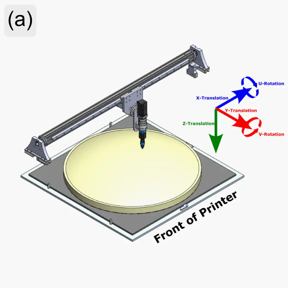
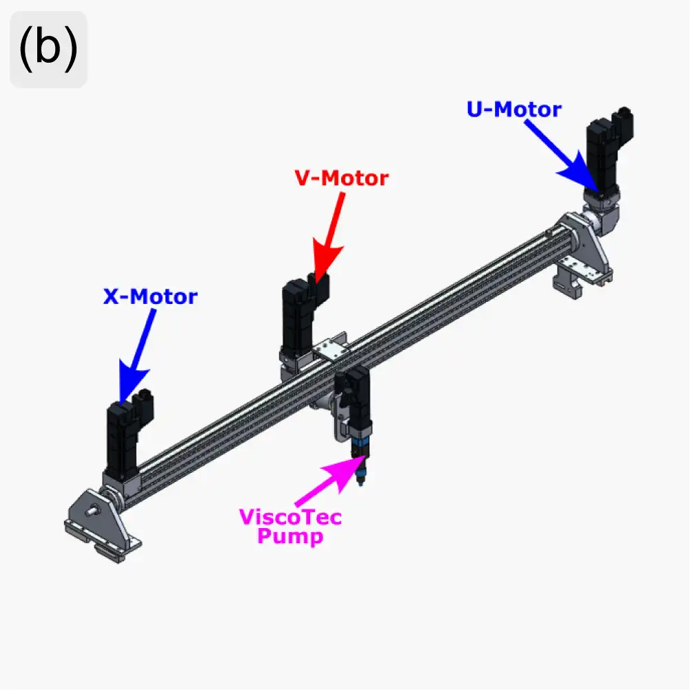
Figure 11: AMTPS printer axes definitions (a) and motor locations (b).
Rather than adapt the Archimajor motherboard for 5-axis control, re:3D collaborated with the Siemens team at the Charlotte Advanced Technology Collaboration Hub (CATCH) to implement an advanced industrial control system. The CATCH team helped identify appropriate servo motors and control hardware for the printer, and also provided training both at a partner solution provider’s site in Houston and at their own Machine Tools facility in Elk Grove Village, Illinois.
For the final touches and commissioning of the printer, the system was sent to Bobby Cole and his team at Think-PLC in Lexington, North Carolina. Think-PLC is a Siemens Solution Partner, and Bobby is highly regarded in the world of industrial controls and automation for his work with machine builders and manufacturers, and re:3D’s experience bears this out. Think-PLC identified and corrected some deficiencies in the AMTPS printer after they received it, then worked to understand the system requirements and implement control kinematics to achieve optimal performance within the limitations of the printer’s mechanical design. It has been great working with them and watching the printer come to life (Figure 12). The AMTPS printer will soon be returning to re:3D in Austin for the installation of the deposition system and the beginning of print testing.
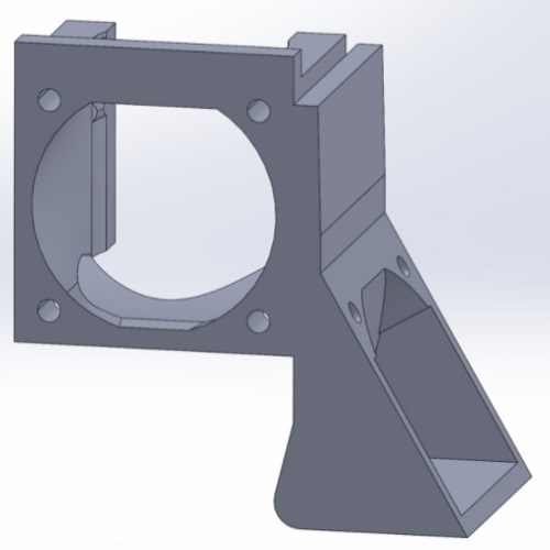
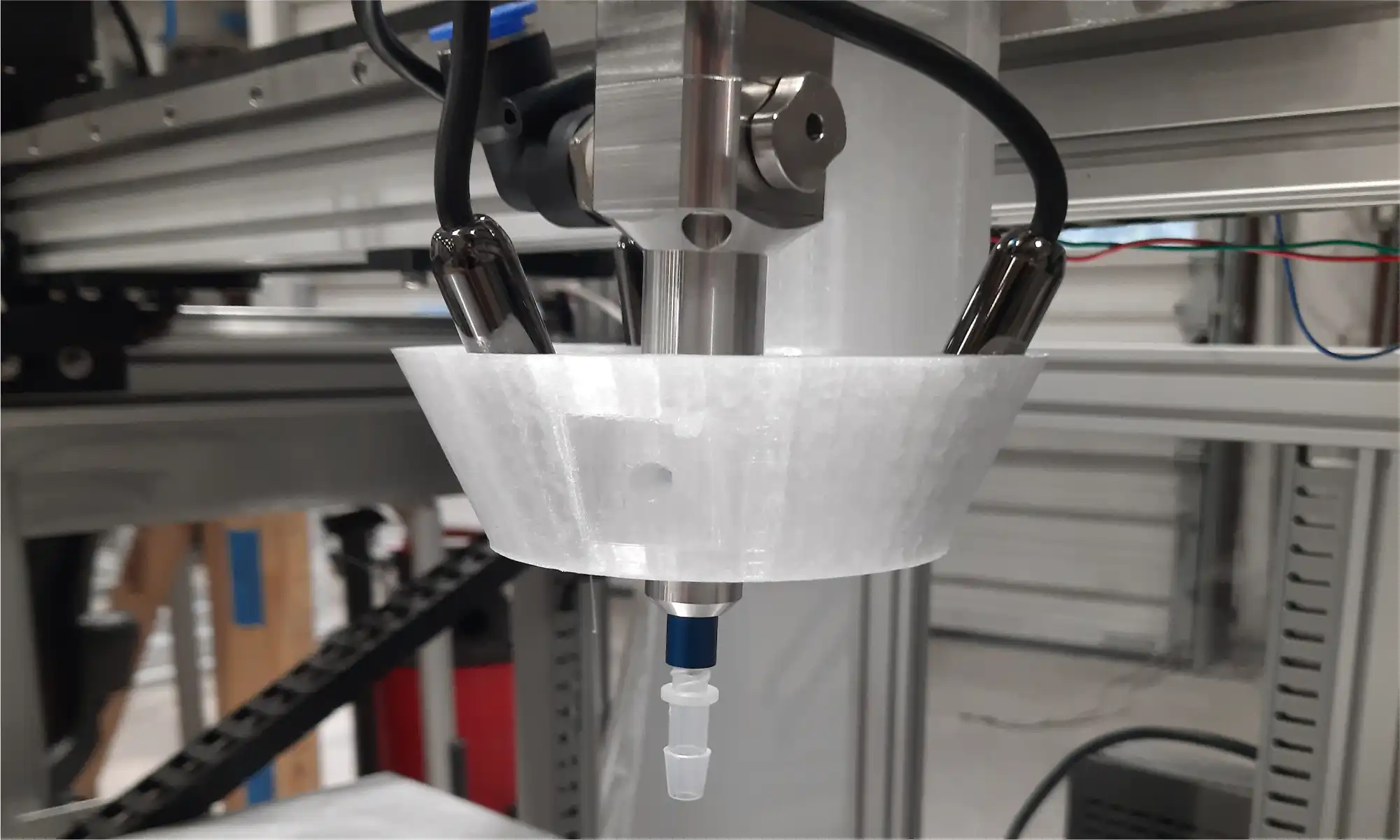
Another collaborator on this project is Addiguru, a software company that specializes in in-situ monitoring technologies for additive manufacturing processes. While re:3D is designing a mounting system for multiple cameras to monitor the deposition of the TPS foam onto the substrate (Figure 13), Addiguru is developing the software to measure the width of the extrusion and flag excessive variances in volumetric deposition in real time. Although it won’t be implemented within the scope of this effort, future work on this project could incorporate Addiguru’s software to provide feedback into the Siemens system for closed-loop control of the deposition process.
Water Bottle Granulation (DOE)
The collaboration with Oak Ridge National Laboratory (ORNL) continues with a focus on separating the recycled PET (rPET) flake from granulated water bottles out of the flake/water slurry coming from the granulator. ORNL is procuring a hydrocyclone for the separation step. Hydrocyclones produce opposing vortices within a chamber which force large, heavy particles out through a reject port and lift lighter fines and liquid out through the overflow. The physics of hydrocyclones is quite interesting and watching YouTube videos about them can easily burn a couple of hours from your day.
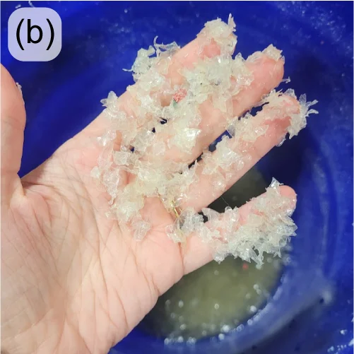
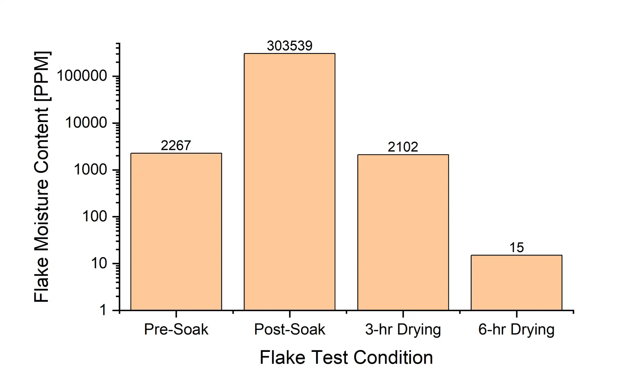
Once the rPET flake is separated from the water it must be dried, and re:3D has been studying the efficacy of desiccant drying on wet flake. A sample of granulated water bottles was soaked in water overnight, then dried in an industrial recirculating desiccant dryer at 70°C. The moisture content of the flake was measured using gravimetric analysis (i.e., loss on drying) at multiple steps throughout the process. As shown in Figure 14, as little as three hours is required to dry the flake back to its original, equilibrium condition, and an additional three hours may be sufficient to dry the flake sufficiently for immediate extrusion processing (below 200 PPM). These results are consistent with re:3D’s previous tests on “Drying rPET Water Bottle Flake”.
It’s a bit of a chore to collect, edit and format the information and photos telling re:3D’s behind-the-scenes technical stories, but it’s also incredibly fulfilling to be able to share the good work going on here and appreciate the cool factor in what we get to do every day. All in all, it’s worth the time.
Thanks for reading along, and as always… Happy Printing!
Patrick, Chris, Mitchell, Taylor
Blog Post Authors