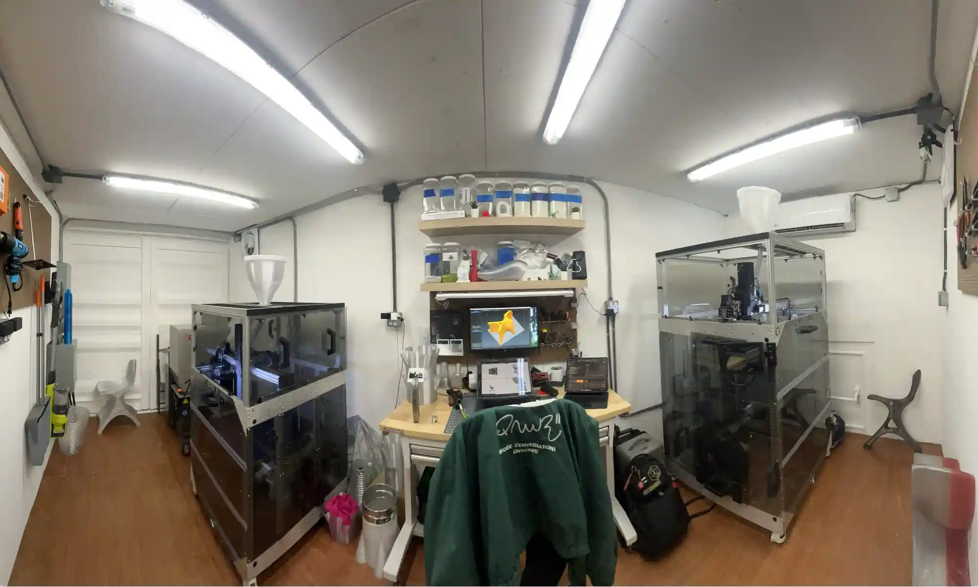


When we set up the Gigalab in Bayamón, Puerto Rico, alongside our neighbors and partners at Engine-4 Foundation, we weren’t just building a container lab. We were planting a seed, an idea that digital fabrication should be for everyone, and that creative tools should serve the people around us.
So we started small. One design, every Friday. Free. Useful. Sometimes funny. Sometimes experimental. Always open.
What started as a small weekly gesture quickly grew into something bigger, a rolling catalog of open-source designs, community responses, and whimsical one-offs that anyone can download, print, and build on. While we’ll be highlighting a few of our favorite moments here, there are plenty more where these came from. So if something catches your eye, or if you’re just curious, we invite you to dive into the rest of our #FreePrintFriday designs on Thingiverse and Cults3D.
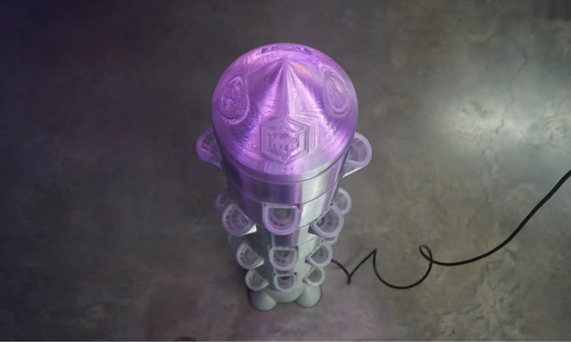
Our 3D printable kite experiment. Still very much a work in progress, but easily one of the most fun things we’ve ever designed. Building something that’s meant to flex, fly, and occasionally crash (gracefully) has pushed us to think differently about material use, weight, and structure—all while showcasing the beauty of recycled 3D printing.
Working alongside our neighbors at Engine-4 Foundation has been core to Gigalab’s mission. Many of the ideas we’ve printed came directly from conversations at Engine-4 with Co-Founder, Luis Torres, whether it was a passing comment, a workshop brainstorm, or someone pointing at a problem and asking, “Can we 3D print a fix for that?”
Some standout collabs include:
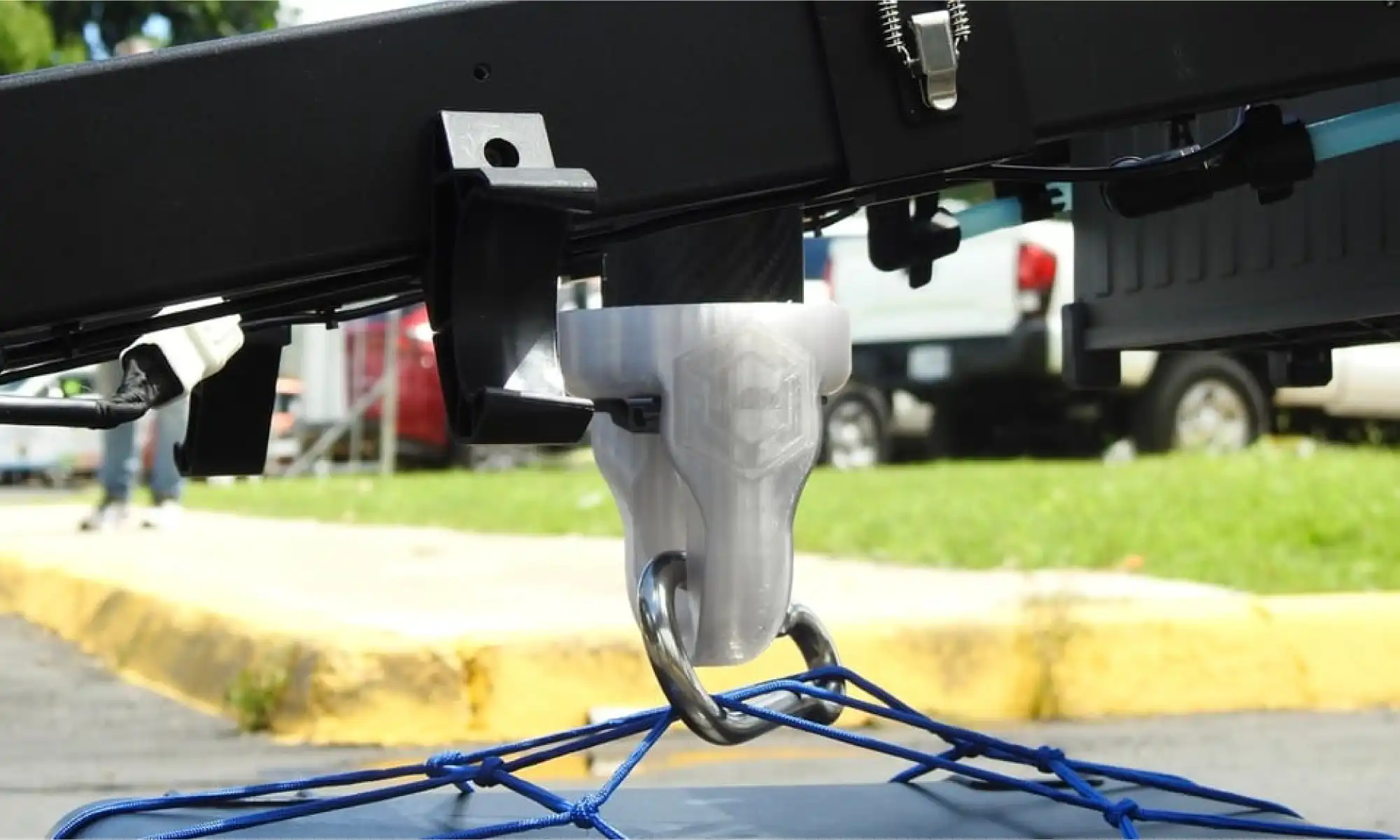
The drone care package hook, a collaboration with both Engine-4 Foundation and the Municipio of Bayamón, used in earthquake simulations to deliver supplies via agricultural drones.
More on the simulation from Puerto Rican local news:
Primera Hora | Telemundo
These kinds of projects remind us that when we design with our community, we design with purpose.
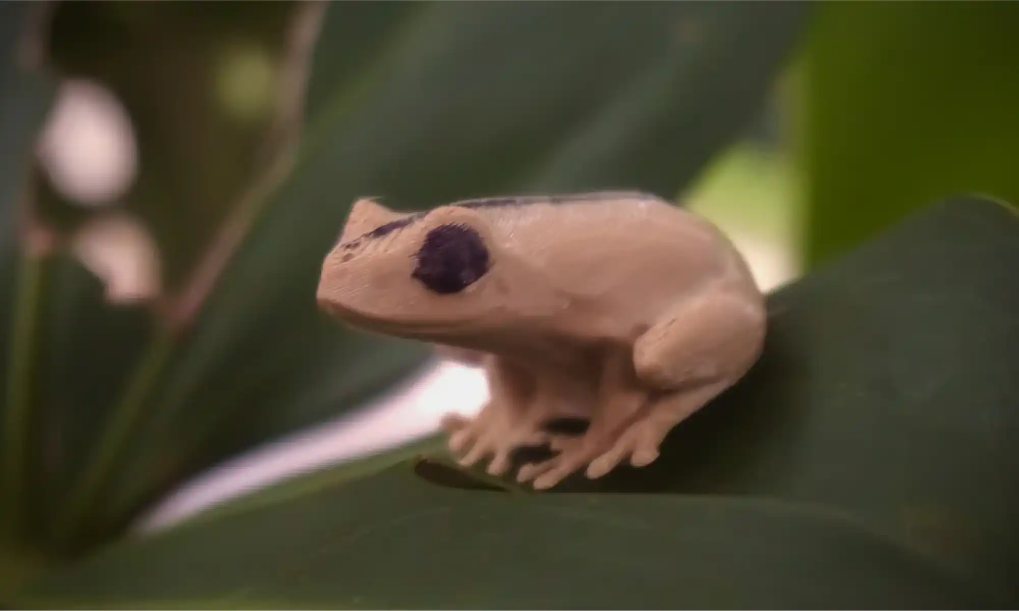
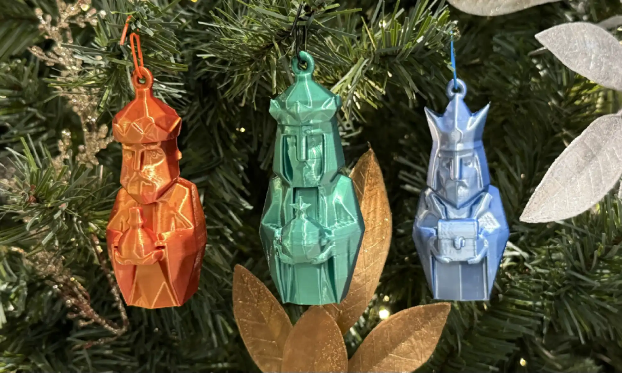
Some of my proudest open-source designs that connect with my Puertorrican identity:
Our photogrammetry model of the Monumento al Jíbaro Puertorriqueño, scanned, modeled, and shared to honor Puerto Rican heritage in a tangible way.
These designs always spark conversation, everything from an “aw” to an “I want one” to someone recognizing their own story in it, saying, “I used to drive past that monument every day. The view was breathtaking.”
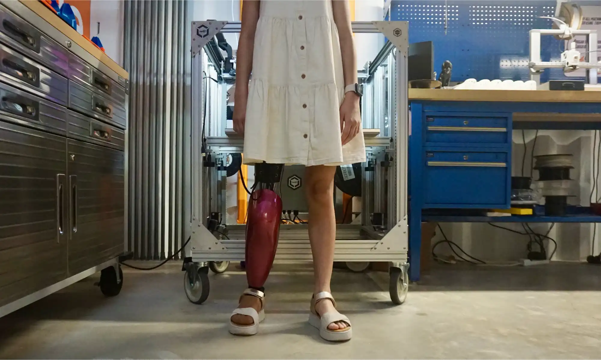
The most personal of our projects came through the Rotationplasty Prosthetic leg shell designs.
It started with a visit. Wilfredo Rodriguez and his daughter Emily came to Engine-4 with a bold question: could we design something that didn’t just cover for her unique rotationplasty prosthetic leg, but make it look and feel amazing? Something Emily could wear with confidence, something that felt like hers.
We scanned her leg using photogrammetry, modeled around it with Rhino and Fusion 360, and started prototyping with rPETG, Nylon, and TPU. Eventually, we found the right balance, lightweight, flexible, and durable enough for everyday life. The final shell was finished with automotive-grade paint for a smooth, protective finish.
But the story didn’t stop there.
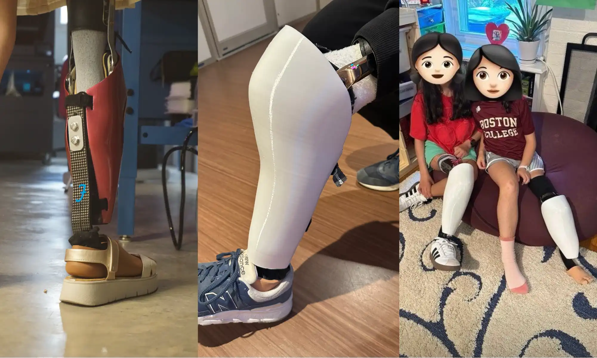
Left is the back of Emily’s cover, middle is daniels cover and right is Emely and Anya
Emily’s friends Anya and Daniel, all the way in Boston, got scanned too. We designed and printed their custom shells right here at the Gigalab in Puerto Rico, and sent them north, each one uniquely shaped and styled for them.
This wasn’t just about aesthetics. It was about saying, with a smile, “I want that leg”
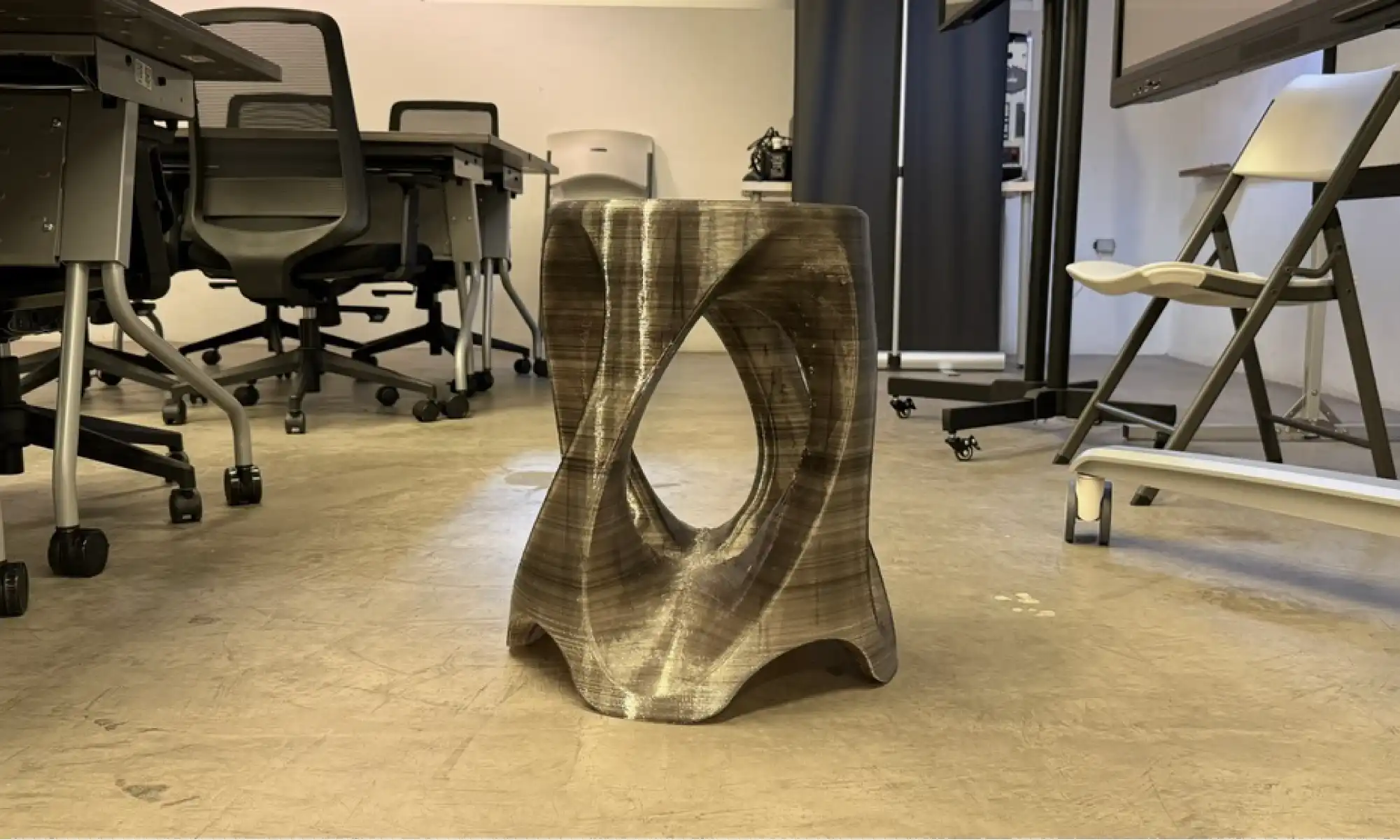
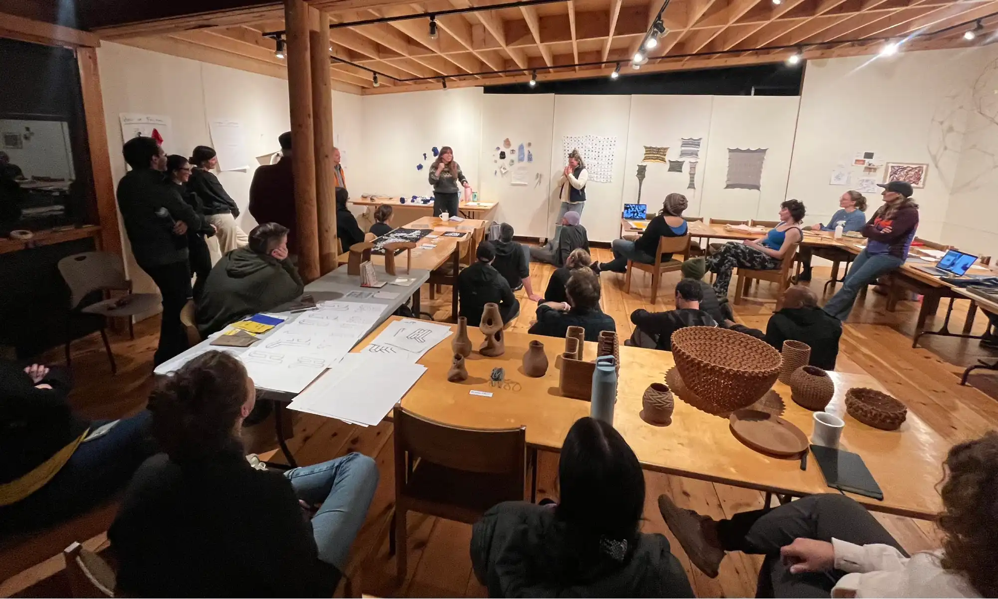
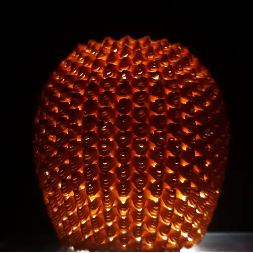
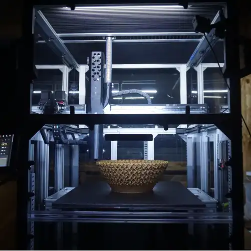
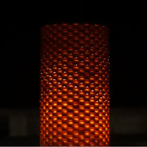
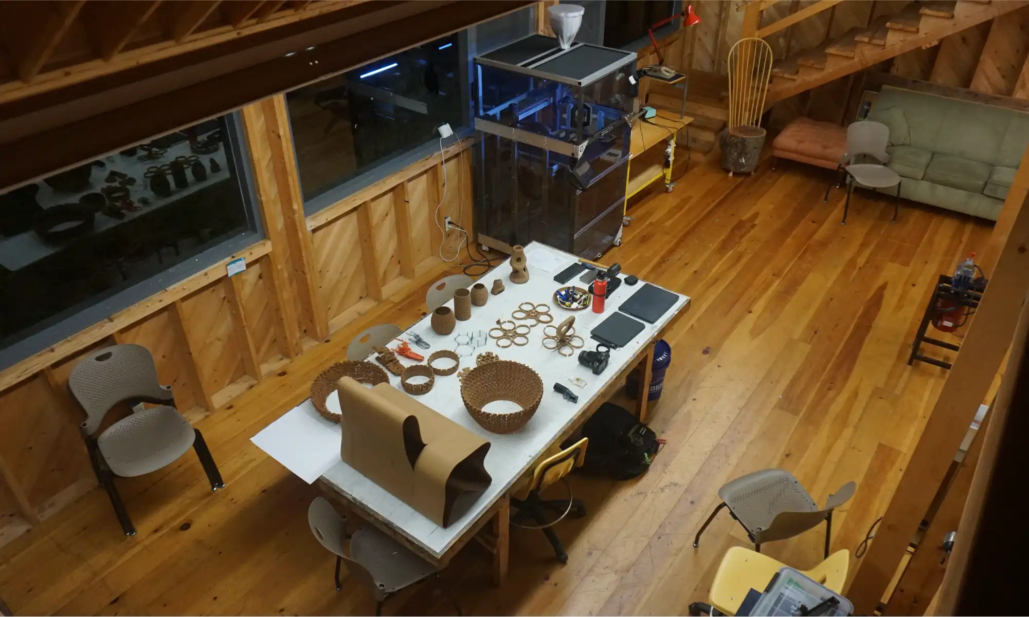
Located on the rugged coast of Deer Isle, Maine, Haystack Mountain School of Craft is a legendary space where artists, designers, and thinkers come together to push creative boundaries. We were lucky enough to be invited to spend a week there with the GigabotX 2 XLT for Haystack Labs, joining a wild mix of tinkerers and craftspeople for a creative tech residency.
At Haystack, we experimented with University of Maine’s wood pulp PLA feedstock, tested out sculptural forms, tricky overhangs, and parametric designs that challenged our printers and our imaginations. We had the pleasure of learning with Shelby Doyle, AIA, an Associate Professor of Architecture at Iowa State University and co-founder of the ISU Computation & Construction Lab. Her expertise in digital fabrication and design-build education brought valuable insights to our explorations, pushing the boundaries of what we could achieve with recycled materials and large-format 3D printing.
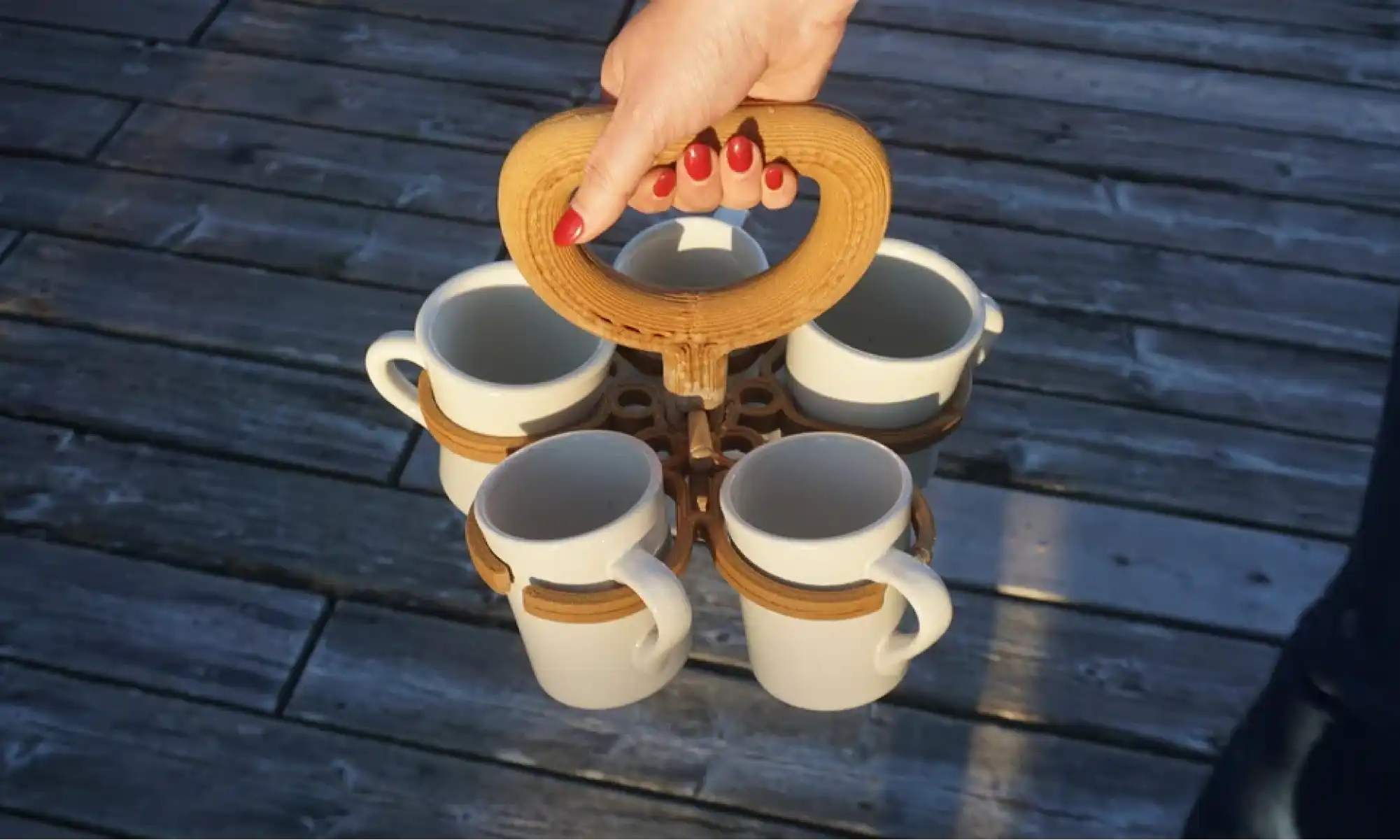
But one of our favorite prints? A five-mug coffee caddy we designed because we were too lazy to take our mugs back to the kitchen one by one. Turns out the kitchen staff liked it too as it’s a recurring problem!
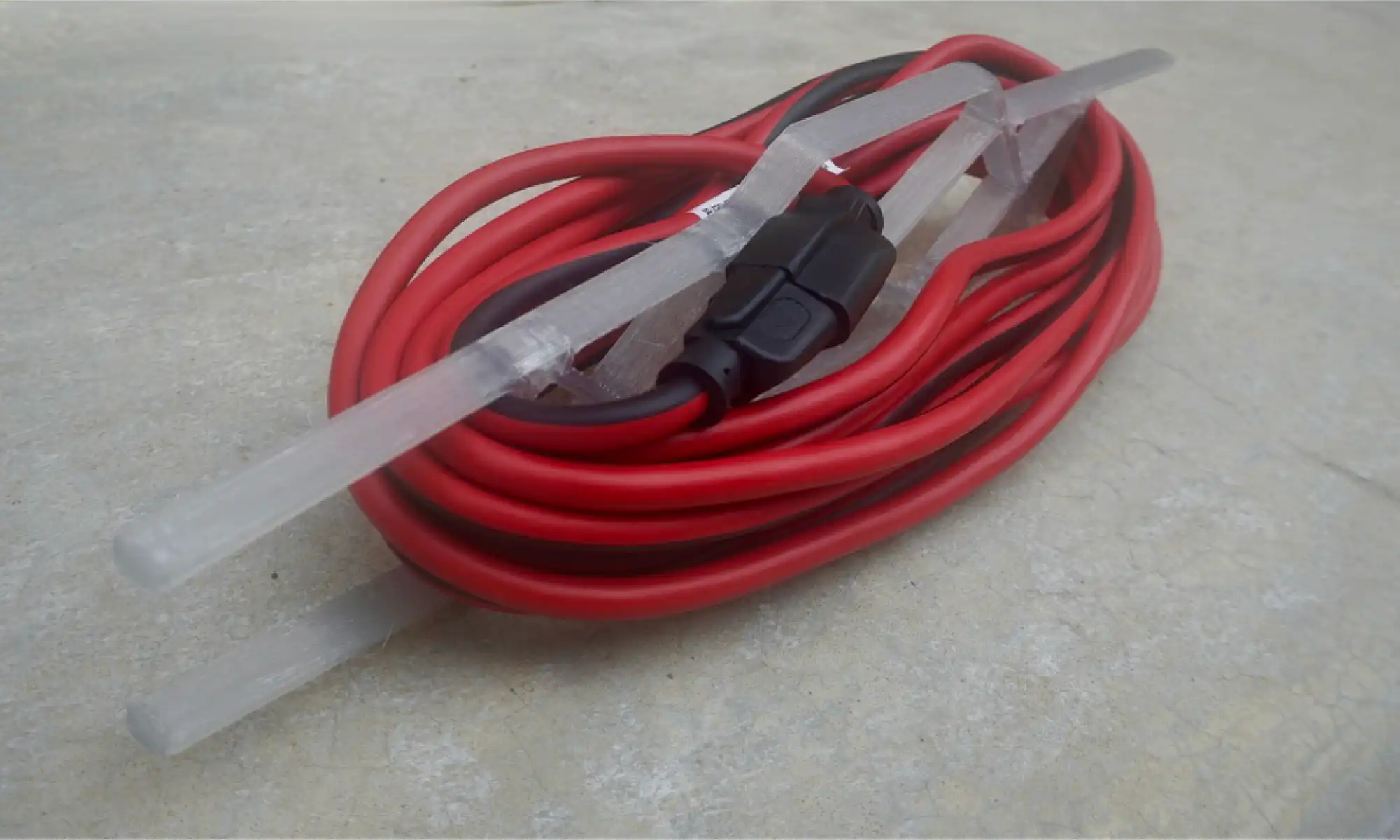
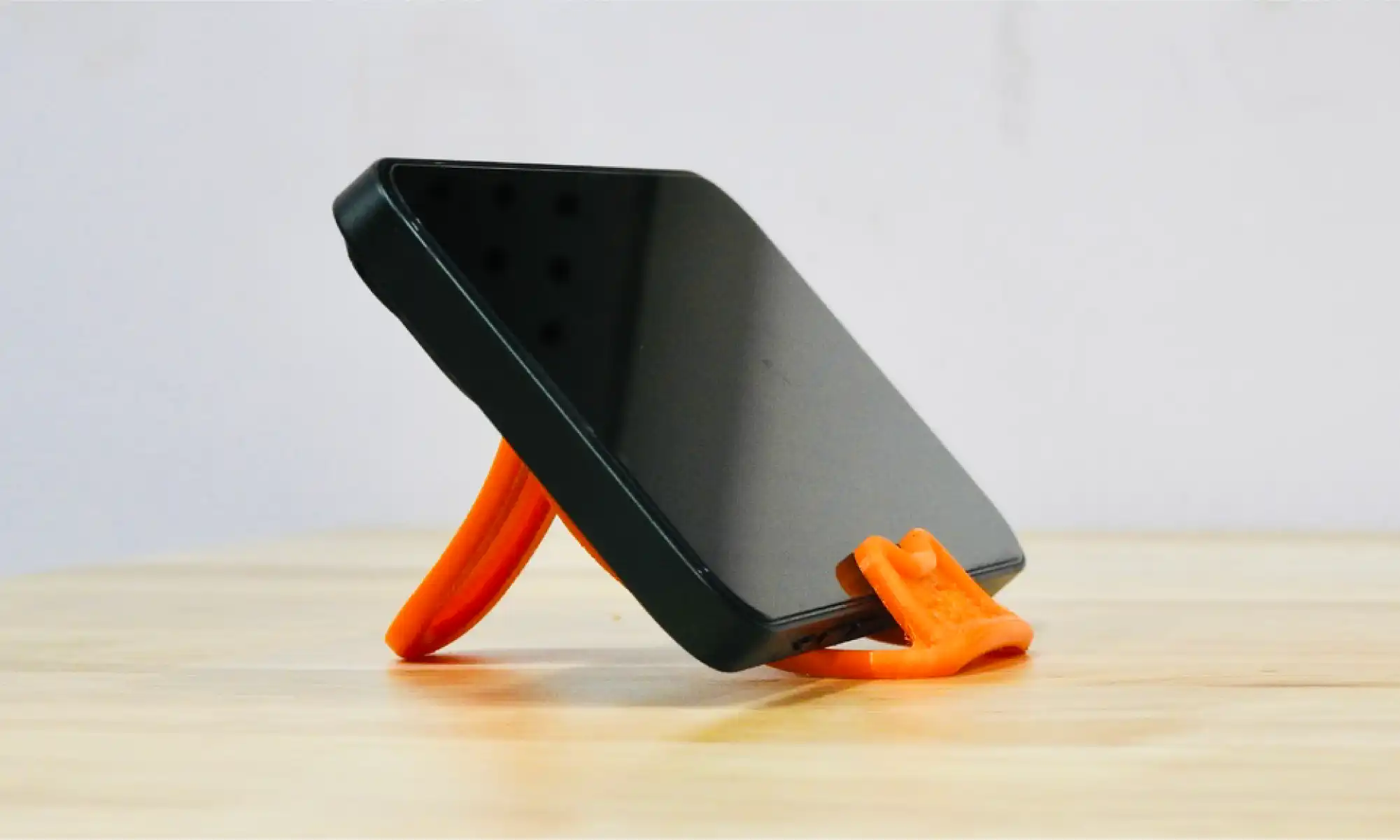
A lot of our most downloaded open-source designs are little things that solve specific, everyday problems stuff that just makes life smoother:
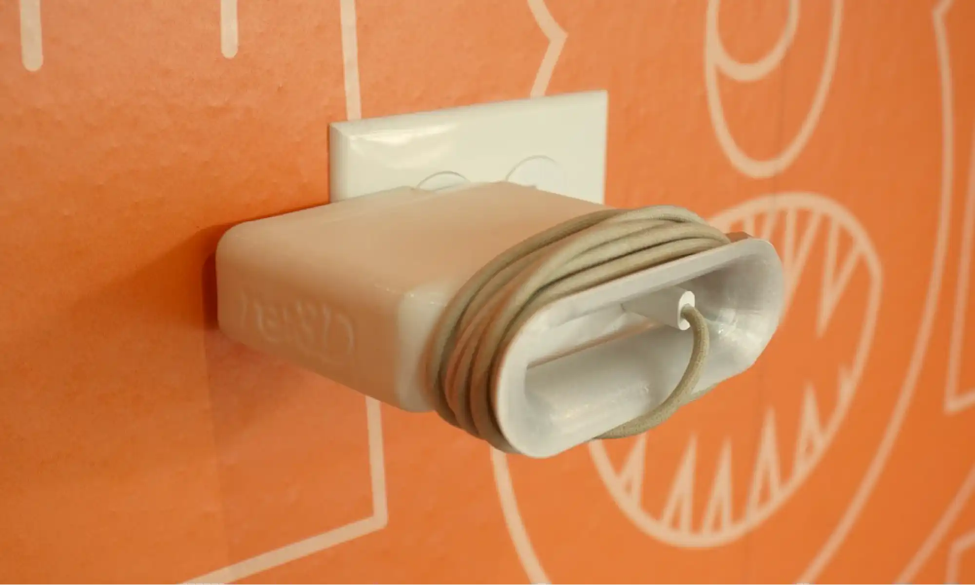
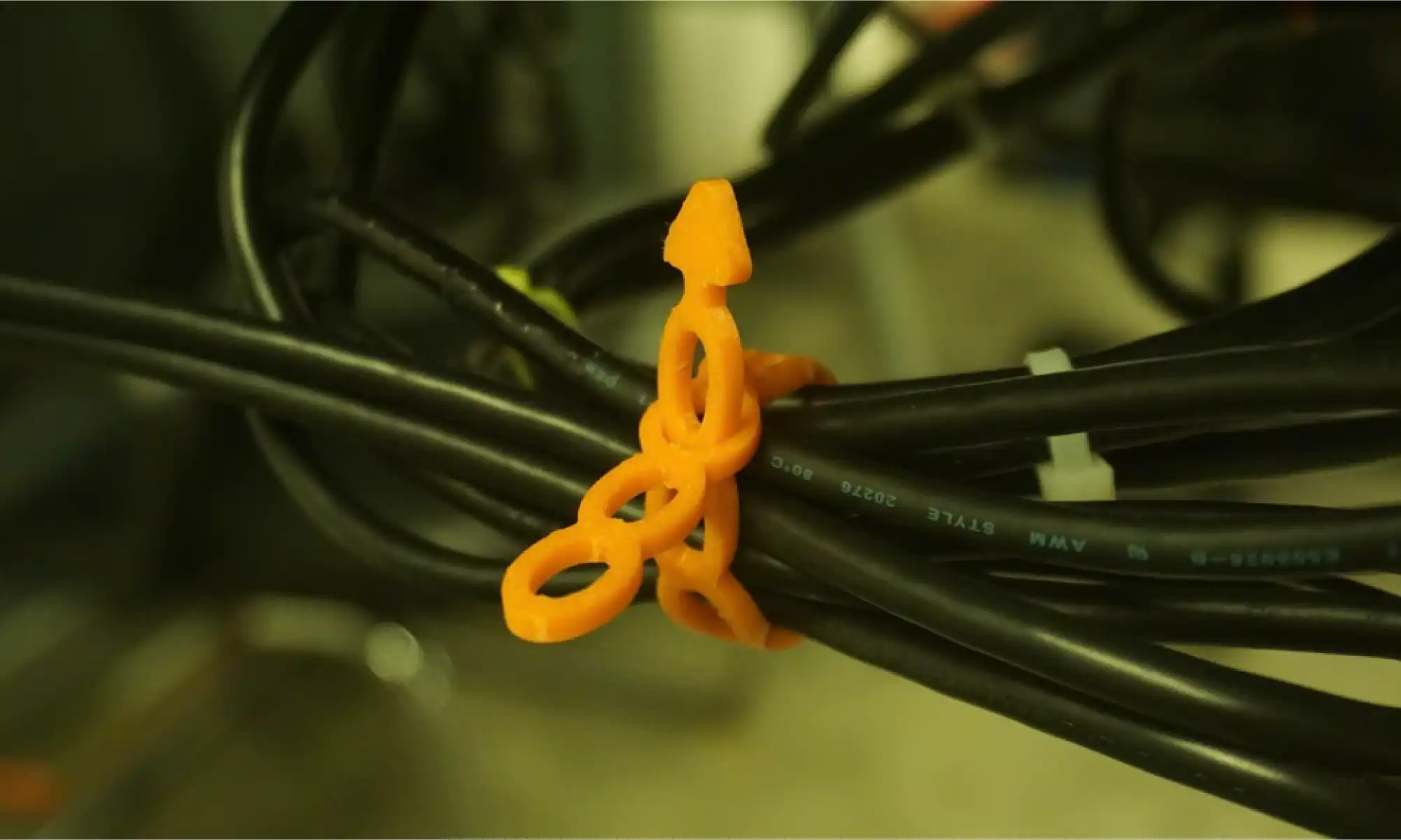
Inspired by SSgt Hart during our Gigalab demo at Cannon Air Force Base, she needed a better way to manage cables, had a great idea, sketch it out for us and we helped turn that need into a print anyone can use!
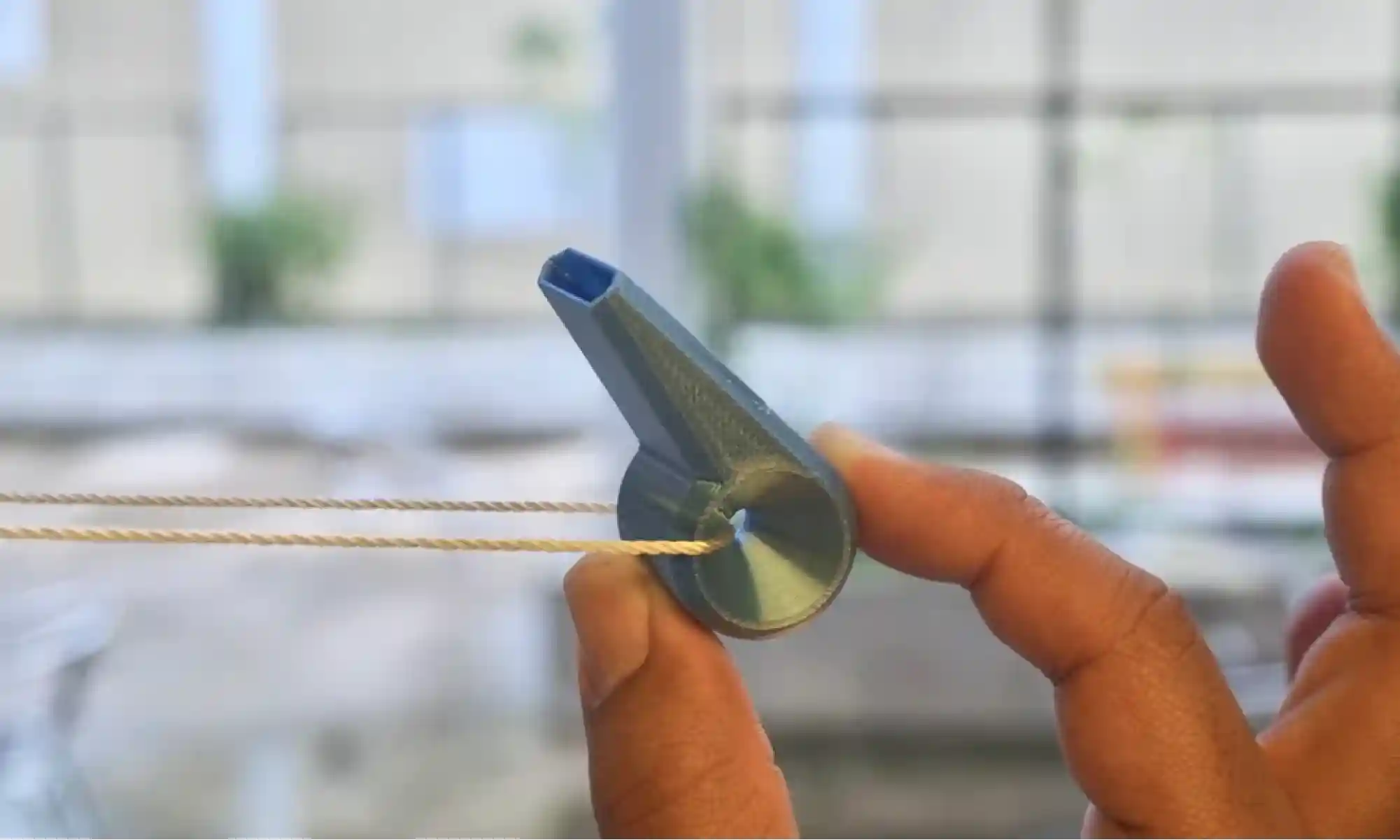
These weren’t built for retail. They were built for daily use, most came to life in under an hour, sparked by someone asking, “Hey, can you print something for this?” or even just a playful thought like, “What if we 3D print a whistle?”
Over the past year, we’ve shared over 50 open-source designs. Some are silly. Some are super niche. Some are actually really useful. Most are a little of all three.
What they all have in common is this: they came from the community, and they’re going back to the community. Free. Open. Ready to print.
Whether it’s a bookmark, a birdhouse, or a prosthetic leg cover, every design came from a simple idea: listen, learn, make, and share.
We believe 3D printing isn’t just a trend. It’s a tool for local problem solving, education, expression, and play. That’s why we do #FreePrintFriday .
We’ve still got a backlog of unreleased prints. Expect more cultural remixes, more functional tools, more weird stuff. Maybe even more community collabs!
Got an idea? Shere it with us by filling out our #FreePrintFriday form, we’d love to hear it!
Here’s to another year of printing what matters (and what’s fun). See you Friday and happy printing!
– Michael C. Pujols Vázquez and re:3D team
Michael C. Pujols Vázquez
Blog Post Author

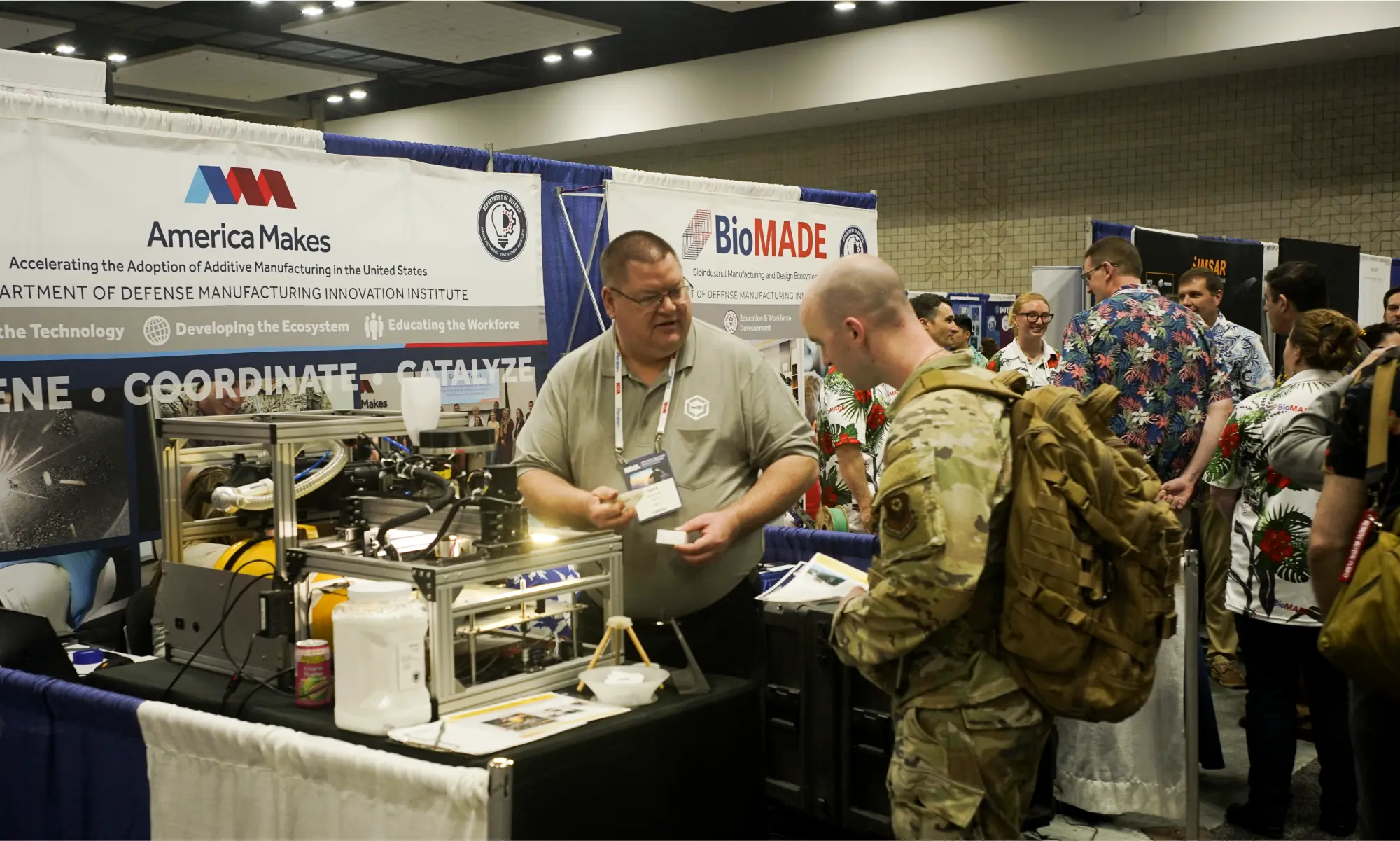
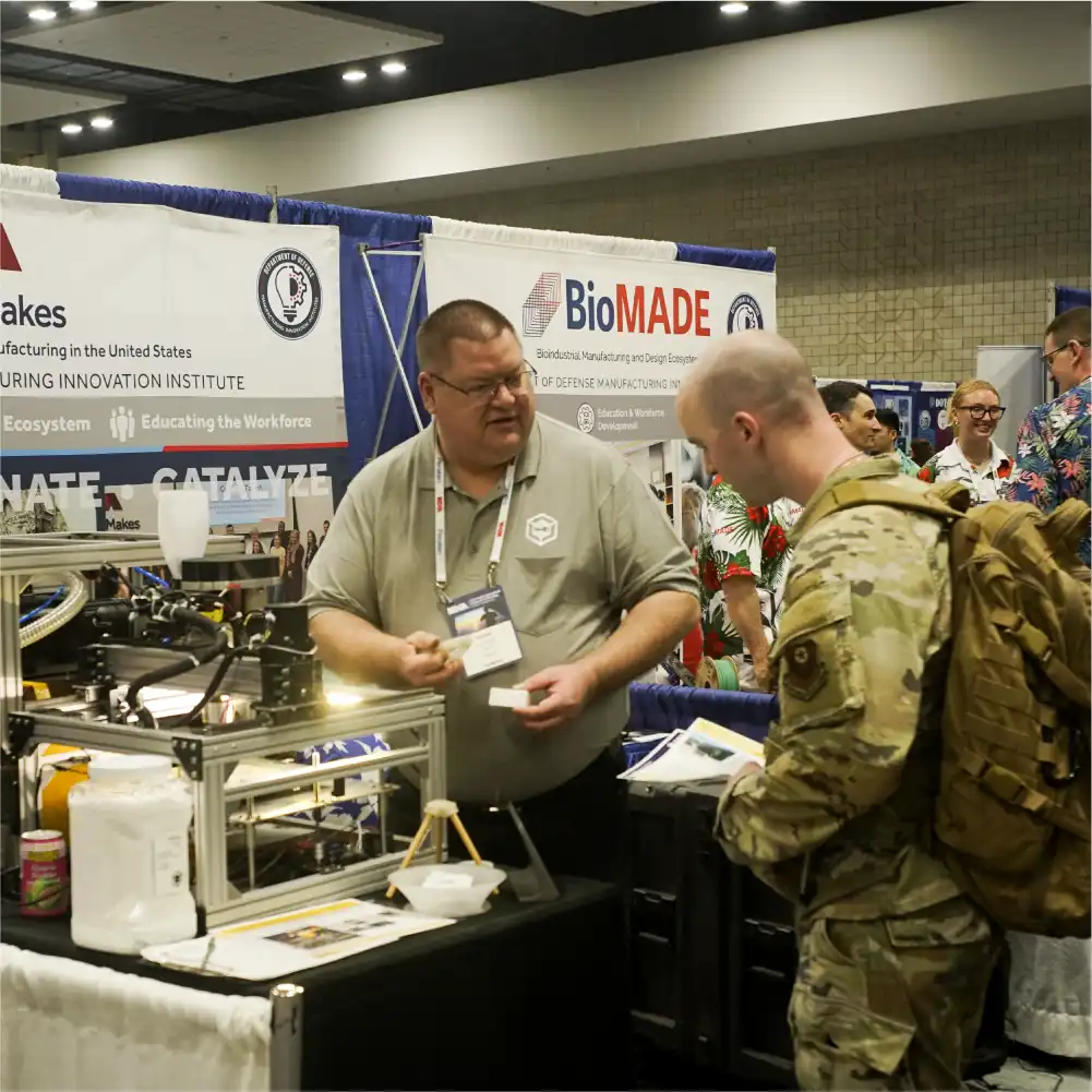
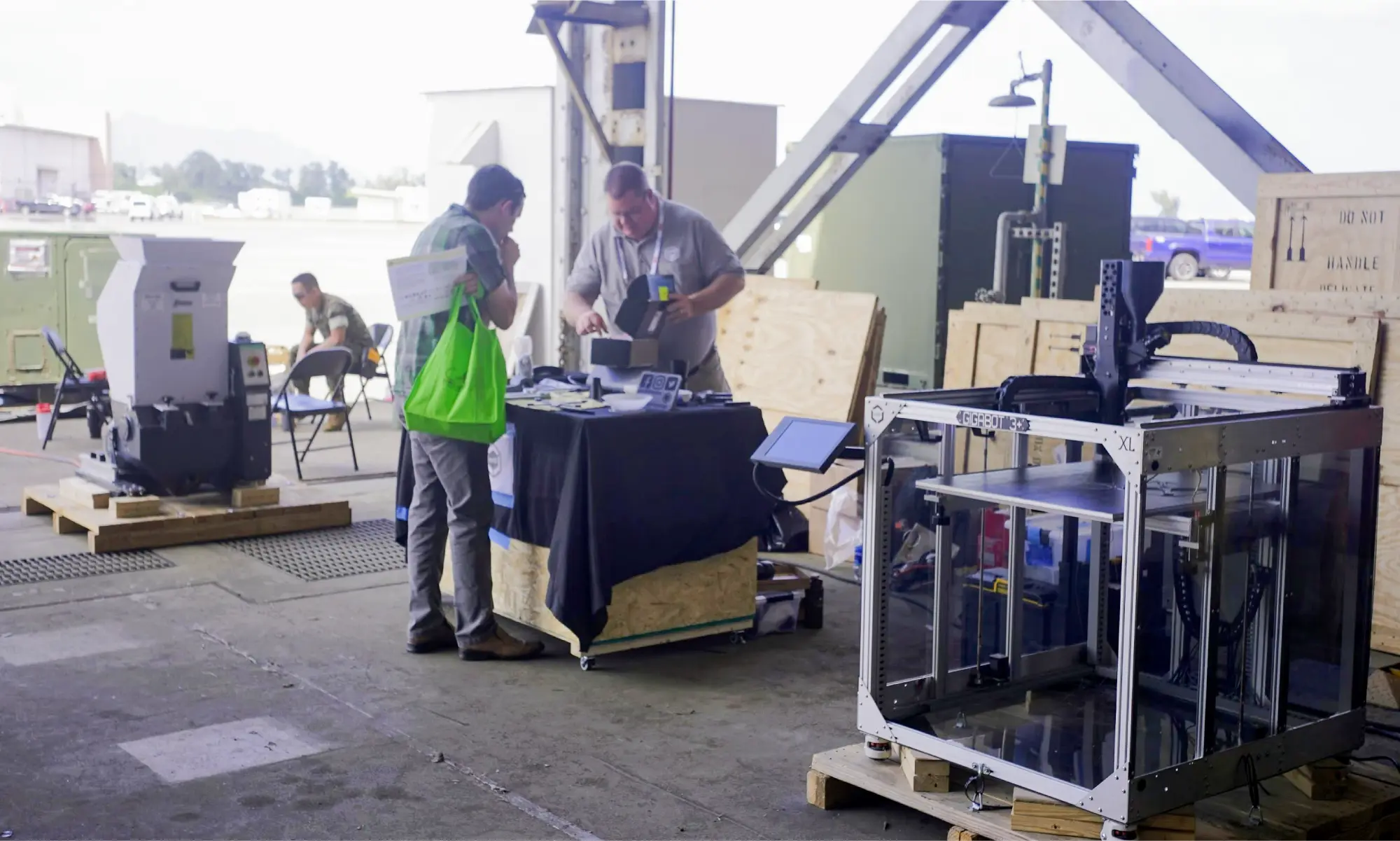
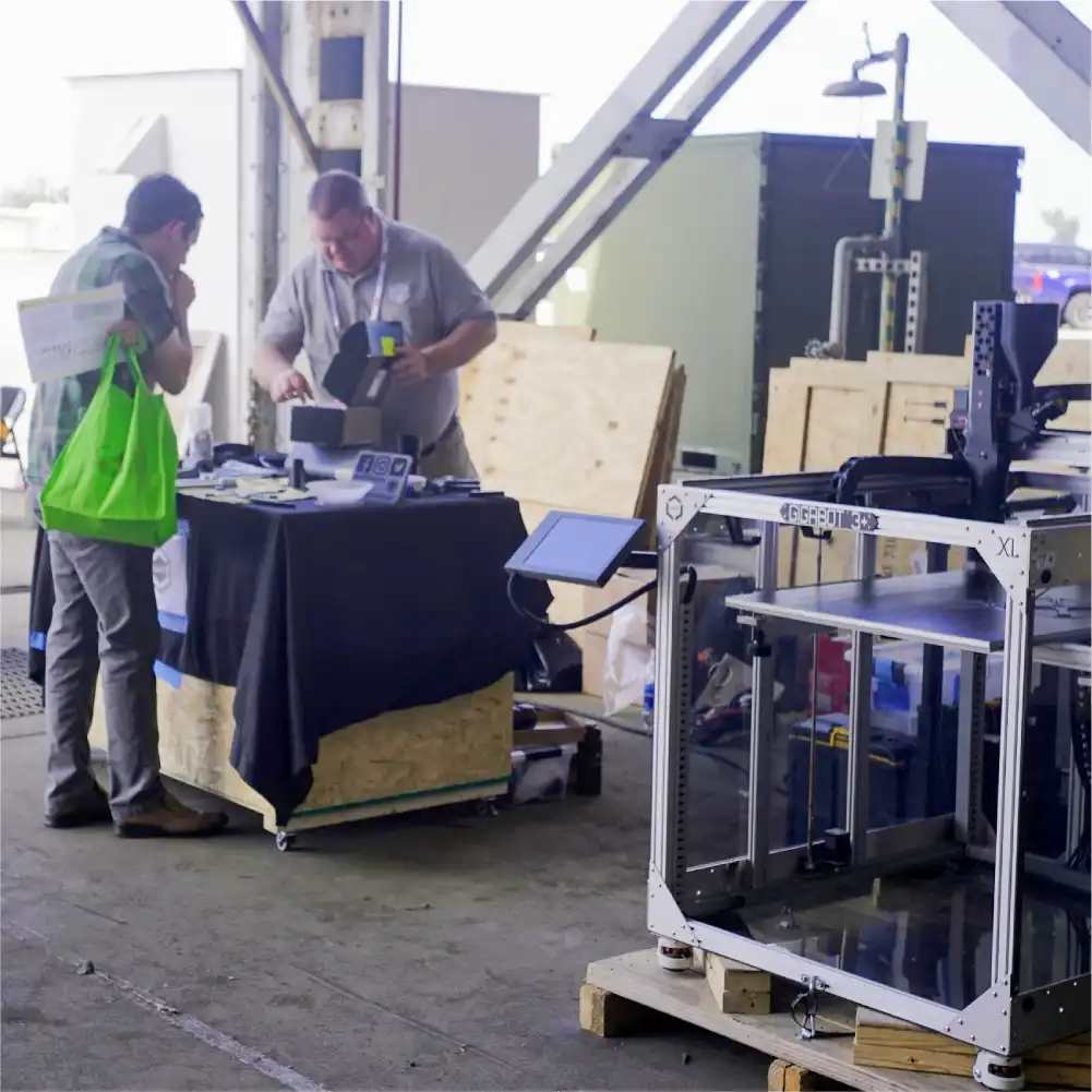
re:3D is a proud and active member of America Makes, an organization which works to accelerate the adoption of additive manufacturing (AM) and supports global U.S. manufacturing competitiveness as one of nine Manufacturing Innovation Institutes (MIIs) operated by the Department of Defense (DOD). re:3D was invited by America Makes to join them in their expo booth at the 2025 Pacific Operational Science and Technology (POST) conference, recently held in Honolulu, Hawai’i. POST, hosted by the National Defense Industry Association, provides a venue for collaboration between the DOD, academia and industry to address challenges within the Indo-Pacific theater.
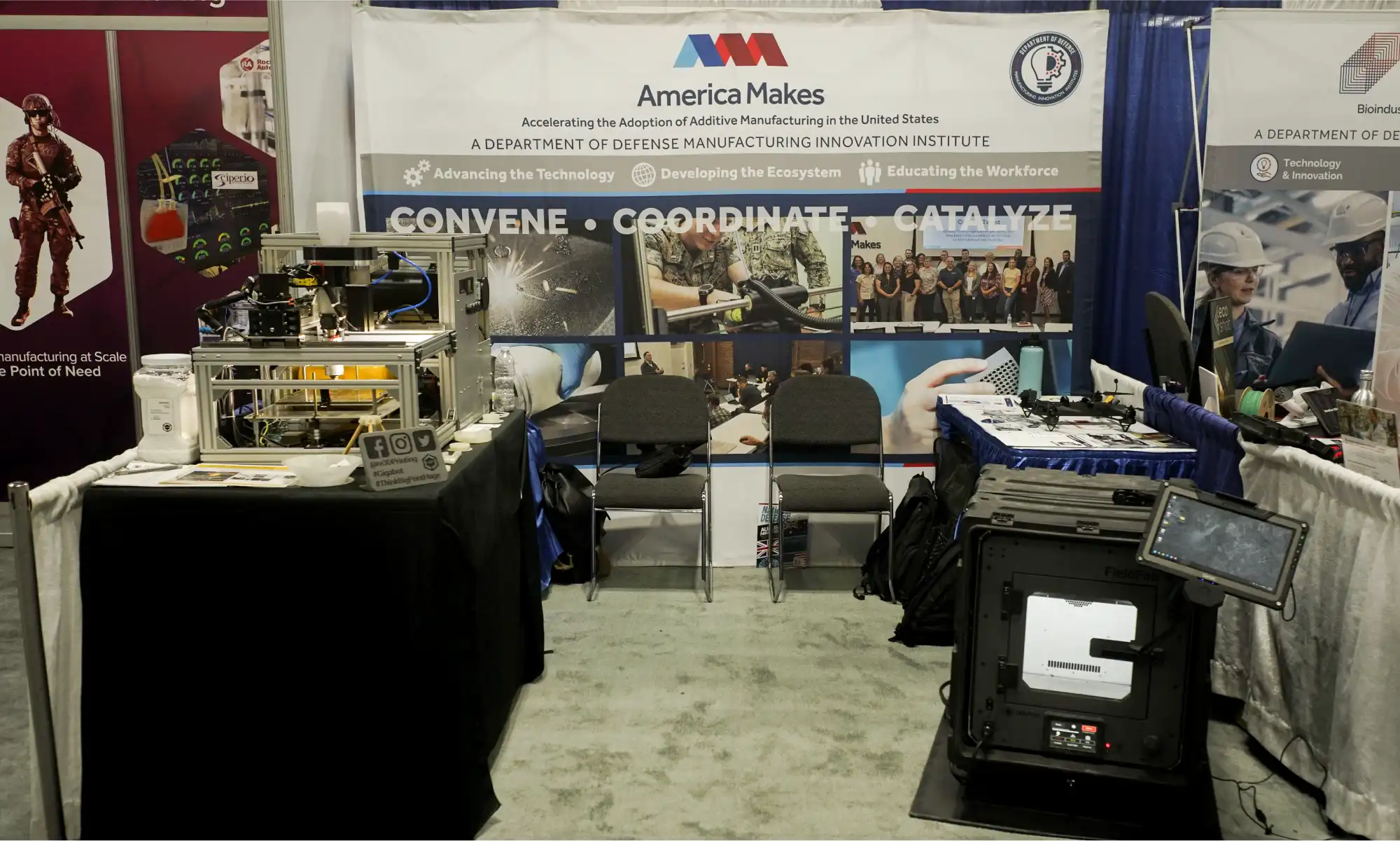
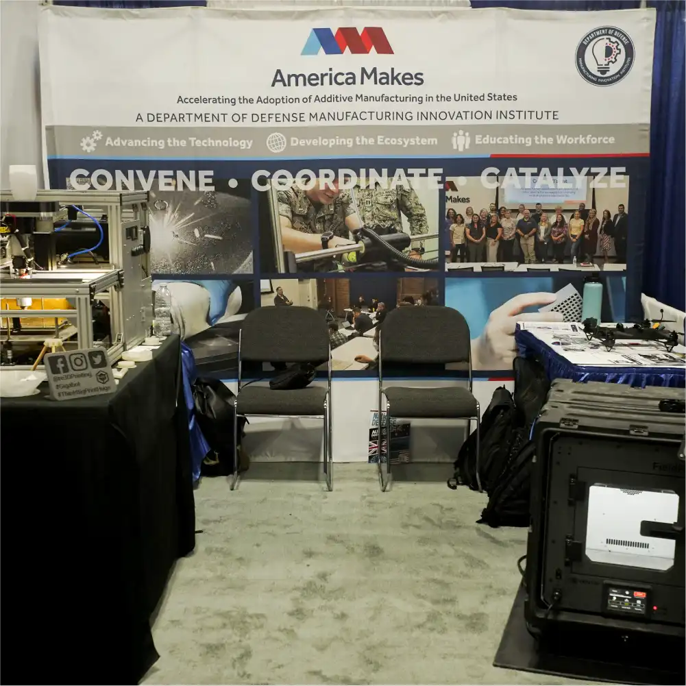
During the expo, re:3D displayed and demonstrated a system under development for NASA to convert logistics waste into articles of need in space, along with discussing the company’s several Gigalab projects. (You can read a bit more about those projects in a previous blog post here.) There was a positive response to these projects with good feedback and some new contacts and references to follow up with for future collaborations. The America Makes team, including their representatives at POST, Ed Herderick and Kimberly Gibson, were fantastic partners and hosts.
Also sharing the booth was another America Makes member company, Craitor. The team at Craitor has worked closely with units across service branches to develop an expeditionary 3D printer capable of operating in extreme environmental conditions. Their FieldFab printer can keep printing while being violently jostled in the back of a moving truck, caught in a -40°C blizzard or drenched in a tropical monsoon. Their booth display has the FieldFab mounted on a wobble-table so you can kick the printer while it’s running – something we’ve probably all wanted to do at one time or another. It was great meeting Eric Shnell, Dan Valdes and Will Landry at the event. The re:3D team wishes them all continued success.
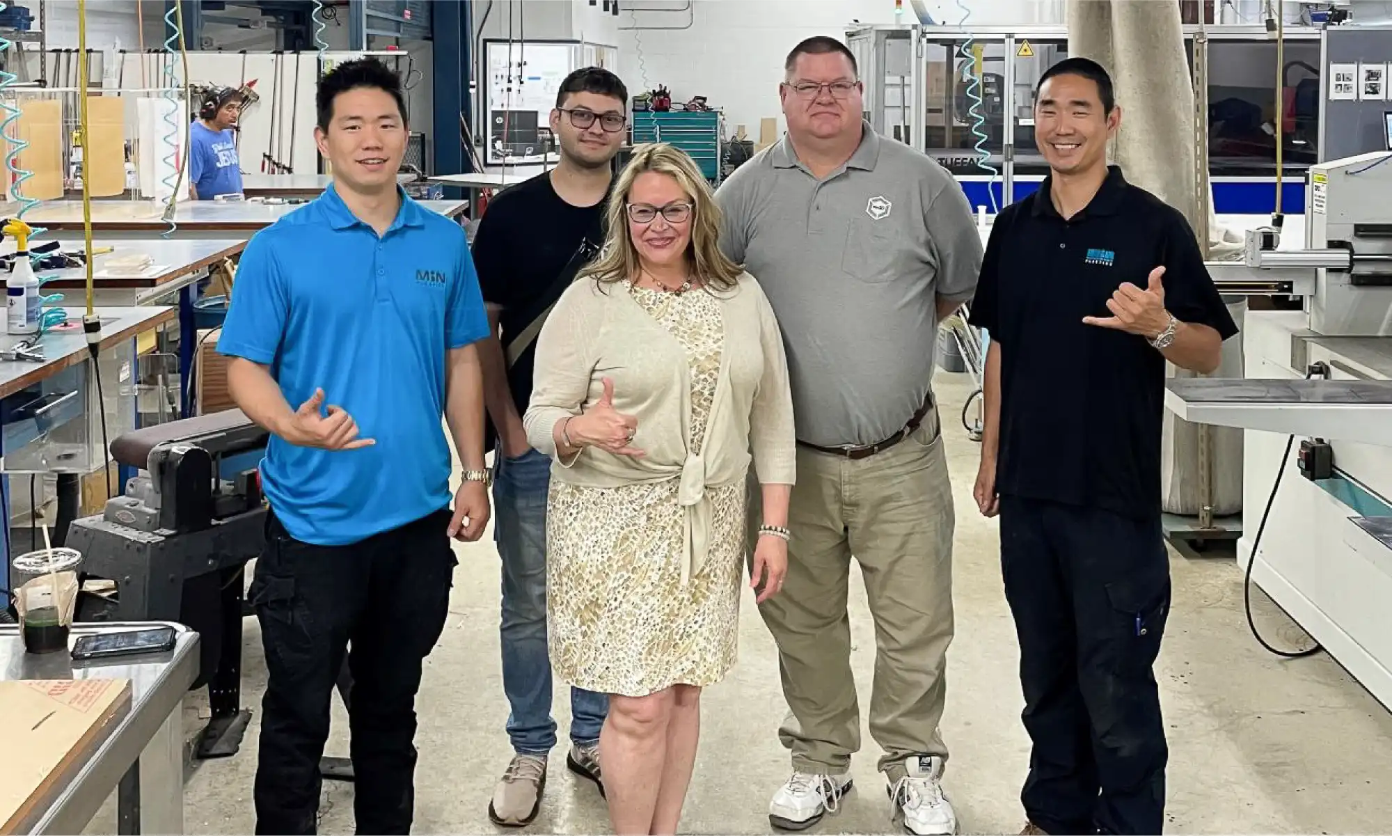
Midweek, after the expo was over, Kimberly Gibson arranged for re:3D to visit Min Plastics & Supply, a family-owned sheet plastics distributor and custom manufacturing company. Andrew and Aaron Min were gracious hosts and discussed possibilities for recycling drops and swarth from their manufacturing processes and using additive for creating custom sign mounts, skylights and tooling. Manufacturing and distributing in the middle of the Pacific Ocean has a whole range of challenges and opportunities to explore, and we look forward to further discussions with the Min Plastics family.

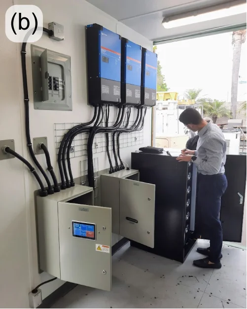
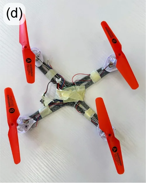
re:3D was also honored to be selected as a demonstrator for the POST Field Experimentation (POST FX), held at the end of the conference at the Marine Corps Base Hawai’i, Kane’ohe Bay. The purpose of POST FX is for demonstrators (mostly government organizations, military units and private companies) to demonstrate technologies or capabilities which support the Indo-Pacific area of responsibility, including priorities for advanced manufacturing and contested logistics which are addressed by re:3D’s Gigalabs and other point-of-need tools using recycled materials. We shipped a granulator and a GigabotX printer to Hawai’i for the POST FX event and demonstrated printing mini drone bodies from reclaimed drones. “Drones from Drones” was an attractive concept to the attendees who stopped by to observe and learn more, including Mr. Michael Holthe – Performing the Duties of Assistant Secretary of Defense for Science and Technology, Office of the Under Secretary of Defense for Research and Engineering.
While in Hawai’i, we were obligated to do a little sight-seeing, and of course we went to a luau. Mike is never one to stop working, so he took the opportunity during the show to scan a large tiki near the stage at the Aloha Tower in Honolulu. He cleaned it up and posted it for all to share and print as his weekly “Free Print Friday” on Thingiverse. You can find the model file here. Mike also scanned the anchor from the USS Arizona on display at the Pearl Harbor National Memorial and has it published here.


The island of O’ahu presented jaw-dropping views everywhere, and the people there really do have a special ‘aloha spirit’, all of which made the looong plane ride worth it. It’s no wonder that Hawai’i is such a popular vacation destination.


Until next time, Happy Travels and Happy Printing.
Patrick Ferrell & Mike Pujols
Blog Post Author

re:3D was on the move last year – literally. But the crew has settled into the new Austin facility with a continued passion for tackling the challenges of additive manufacturing. New faces have joined the Engineering and R&D Teams, and they have all been making impressive progress during the sometimes messy results of a relocation. This is a long-overdue look at some of their recent work.
Early last year there was a company-wide exploration of how and why ‘filament grinding’ was affecting our customers. Follow-up work has focused on cooling methods – both for the extruder mechanism and for part cooling. Improvements in cooling the extruder heat break reduces filament softening (i.e., “heat creep”) in low-temperature materials such as PLA which is a contributing factor to grinding and ultimately print failure. Other thermo-mechanical properties of the extruder are being evaluated as well, with the goal of better thermal management of the filament for more reliable extrusion. Upgrades to part cooling are also being tested. For many thermoplastics, the goal is to extrude above a certain temperature and let the polymer bond to the previously deposited layer (if there is one), and then solidify to maintain the desired geometry as the nozzle travels onward. The rate at which the plastic hardens affects how fast the nozzle can travel without compromising the quality of the print. Often, by appropriately cooling the extruded plastic with forced air, the plastic still bonds, but the geometry is rapidly set and the nozzle can travel faster – ultimately completing the print more quickly. Rapid setting of the polymer also allows for improved performance when printing bridges or overhangs.
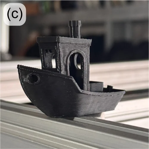
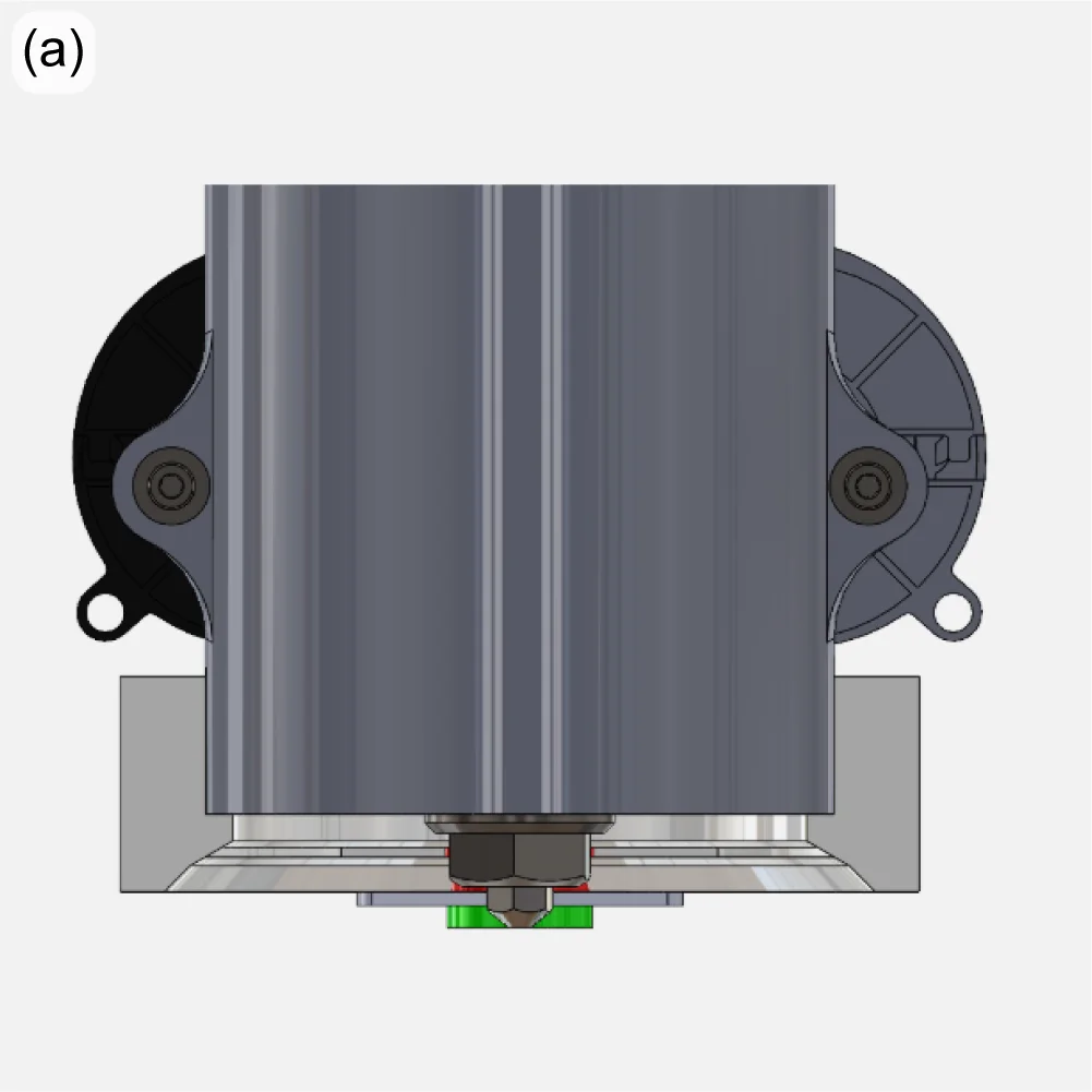
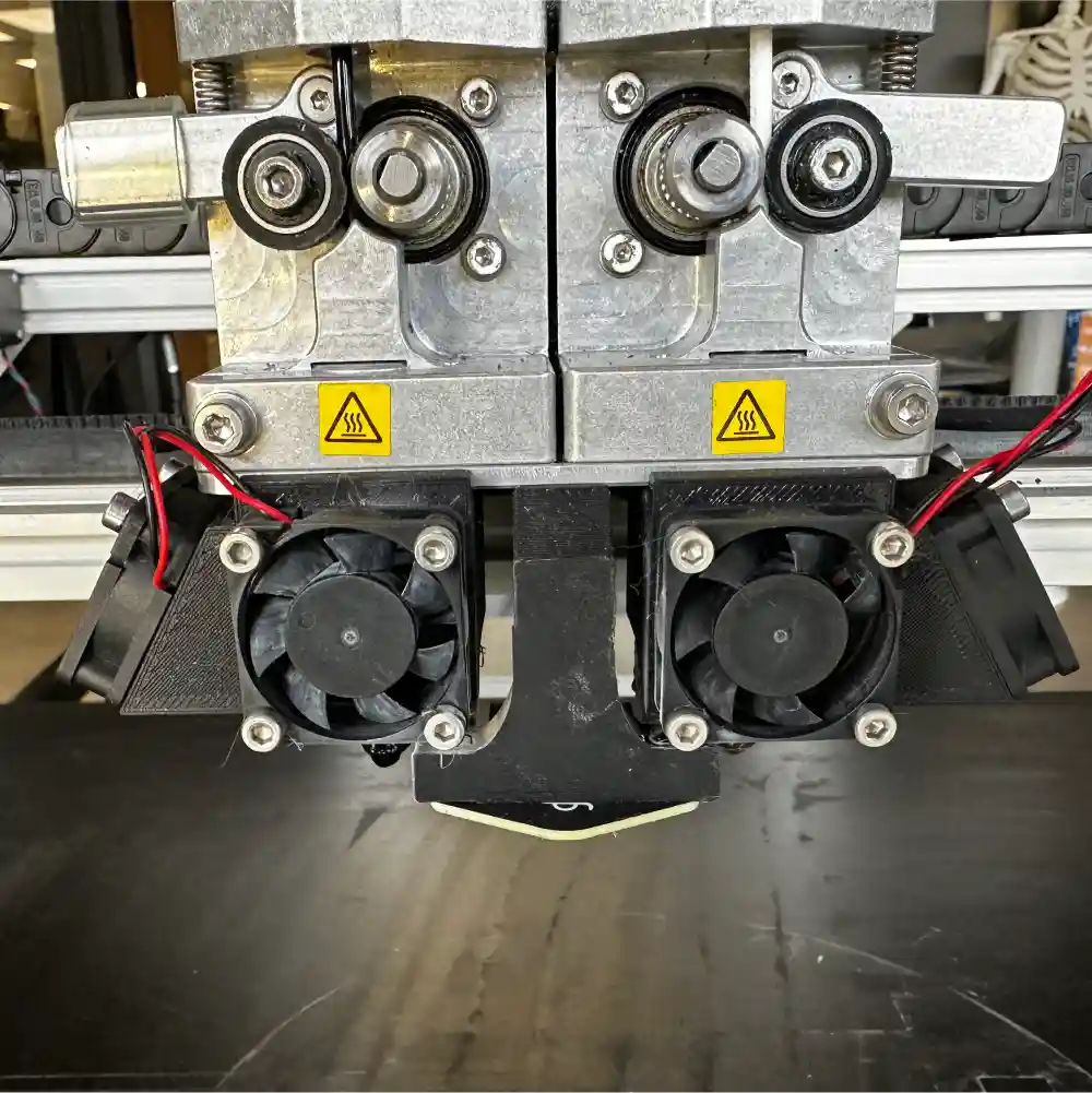
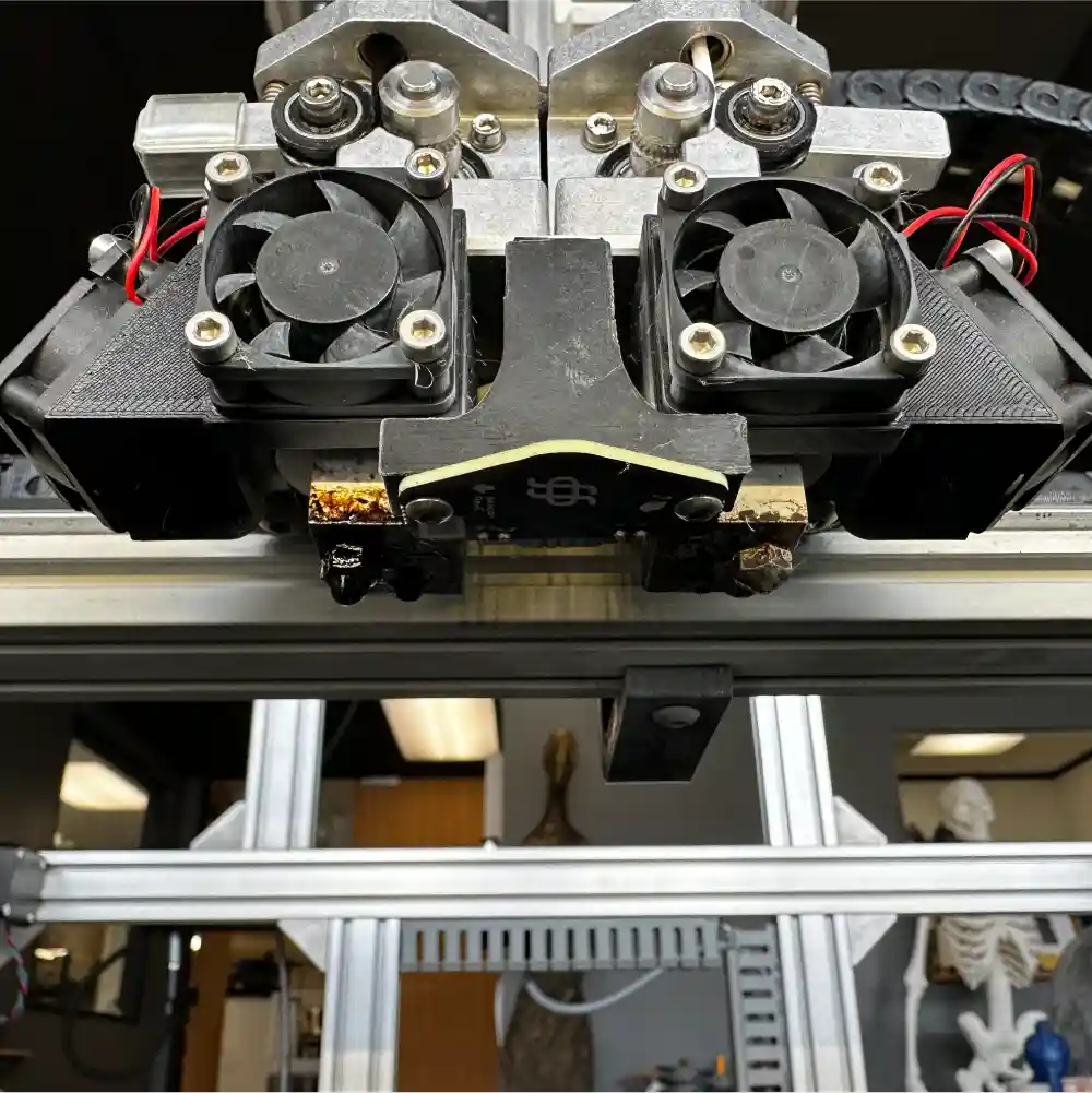
With a new approach to thermal management, small, square axial fans are still used to cool the extruder heat sinks, but radial blower fans are used to provide higher-velocity air at the nozzle tip for part cooling (Figure 1, left and center). With this approach, unsupported overhangs of up to 70° are achieved before scoring “poor” using standard overhang print tests. Print speed can also be dramatically increased. The cooling upgrade allowed a standard 3DBenchy model [1] to be printed in 32 minutes with good quality (Figure 1, right) – down from 70 minutes.
The Engineering Team is also responding to the re:3D user community’s request for a conversion kit to use 1.75mm filament on their Gigabot printers. The new dual-extruder design has been extensively tested on multiple materials internally and will be sent to external beta testers soon.
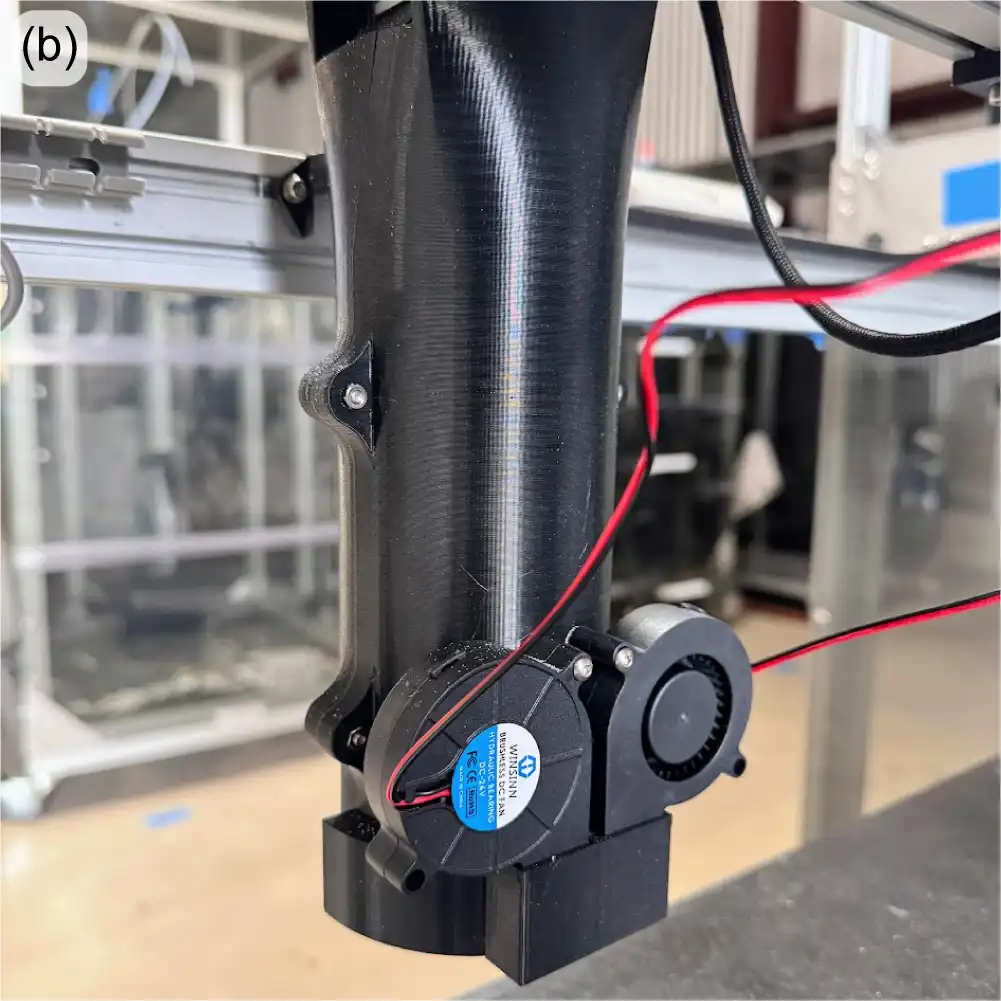
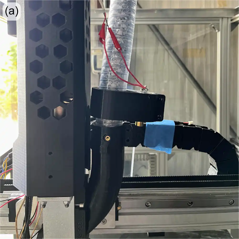
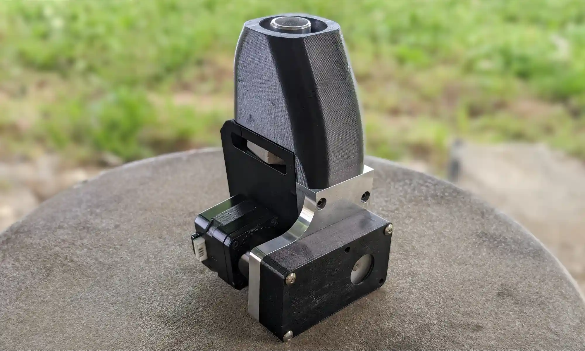
Product development on the GigabotX (GBX) in recent months has been focused on a mount for a bed sensor to incorporate bed mesh compensation software correction, along with an implementation of part cooling for the GBX extruder. Bed mesh compensation will be performed with the same eddy current sensor now under beta test on the Gigabot filament machines, but the design challenge is to create a mechanically stiff mount at the end of the long extruder system. As part of this mount, cooling fans and ducting are being incorporated to provide forced-air part cooling. The reasons for part cooling are described above, but with the larger bead sizes on the GBX, the thermal mass of the extrusion is generally larger, and the need for part cooling is even more critical – especially for bridging and overhangs. It can also promote easier breakaway of support material from the print.
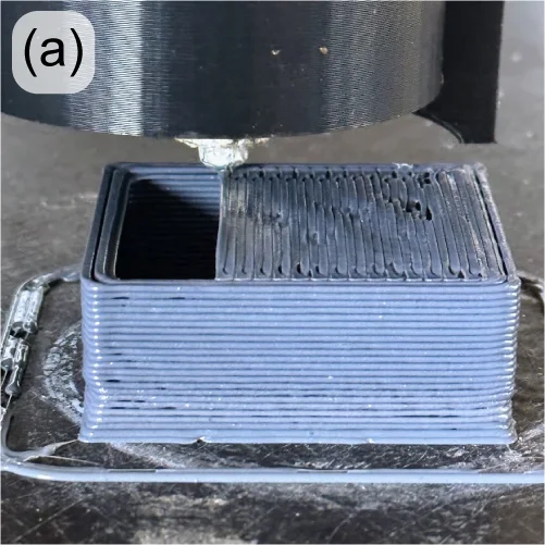
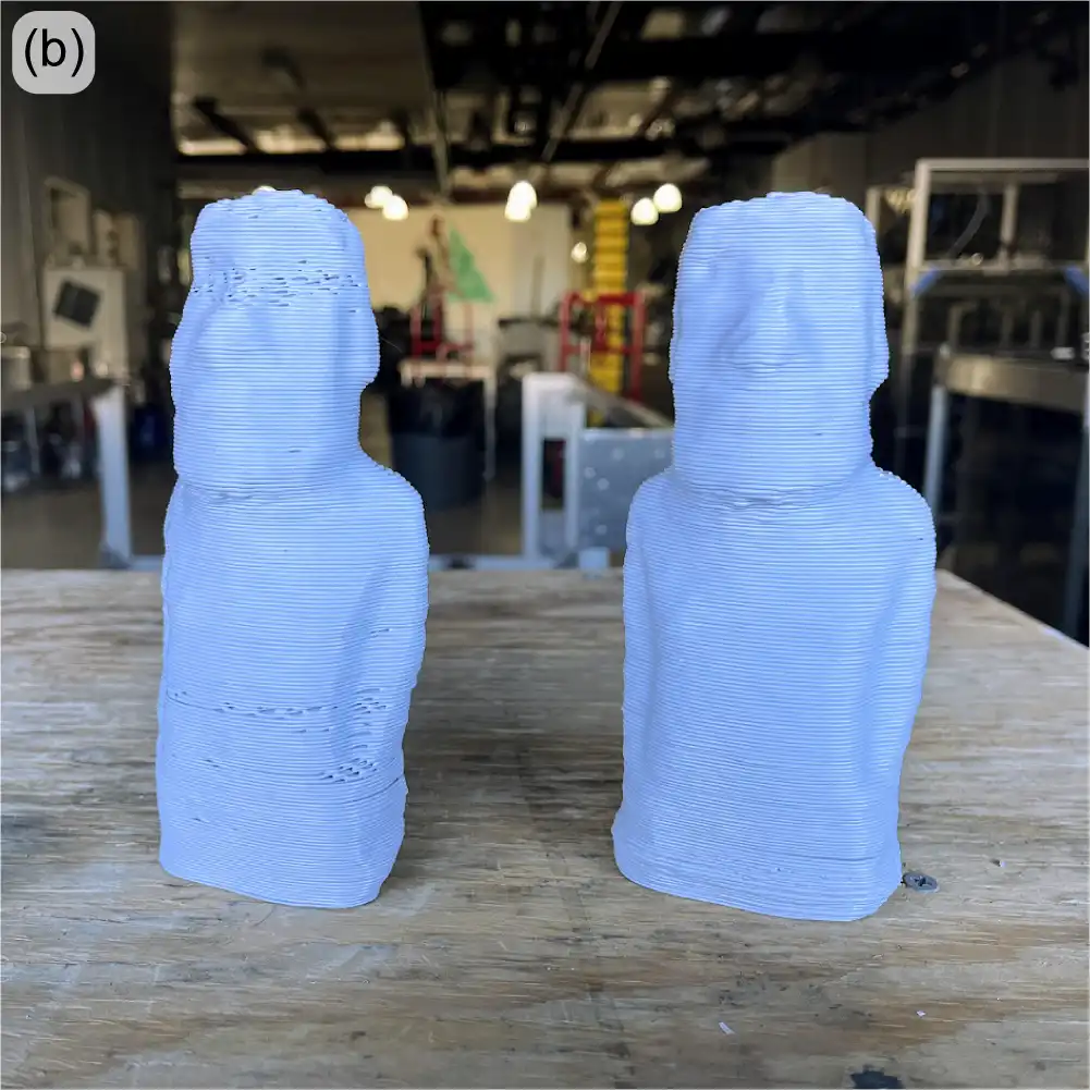
With the part cooling design now under test (Figure 2), PLA is bridging over 40mm with minimal drooping (Figure 3, left) and able to create acceptable bridges and spans over 100mm (Figure 3, right). Overhangs are also improved, and support structures more easily break away by hand, leaving clean parting surfaces.
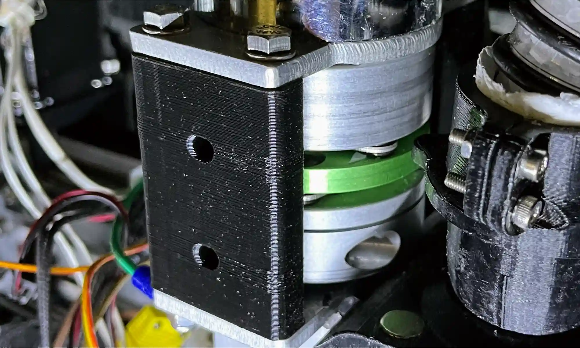
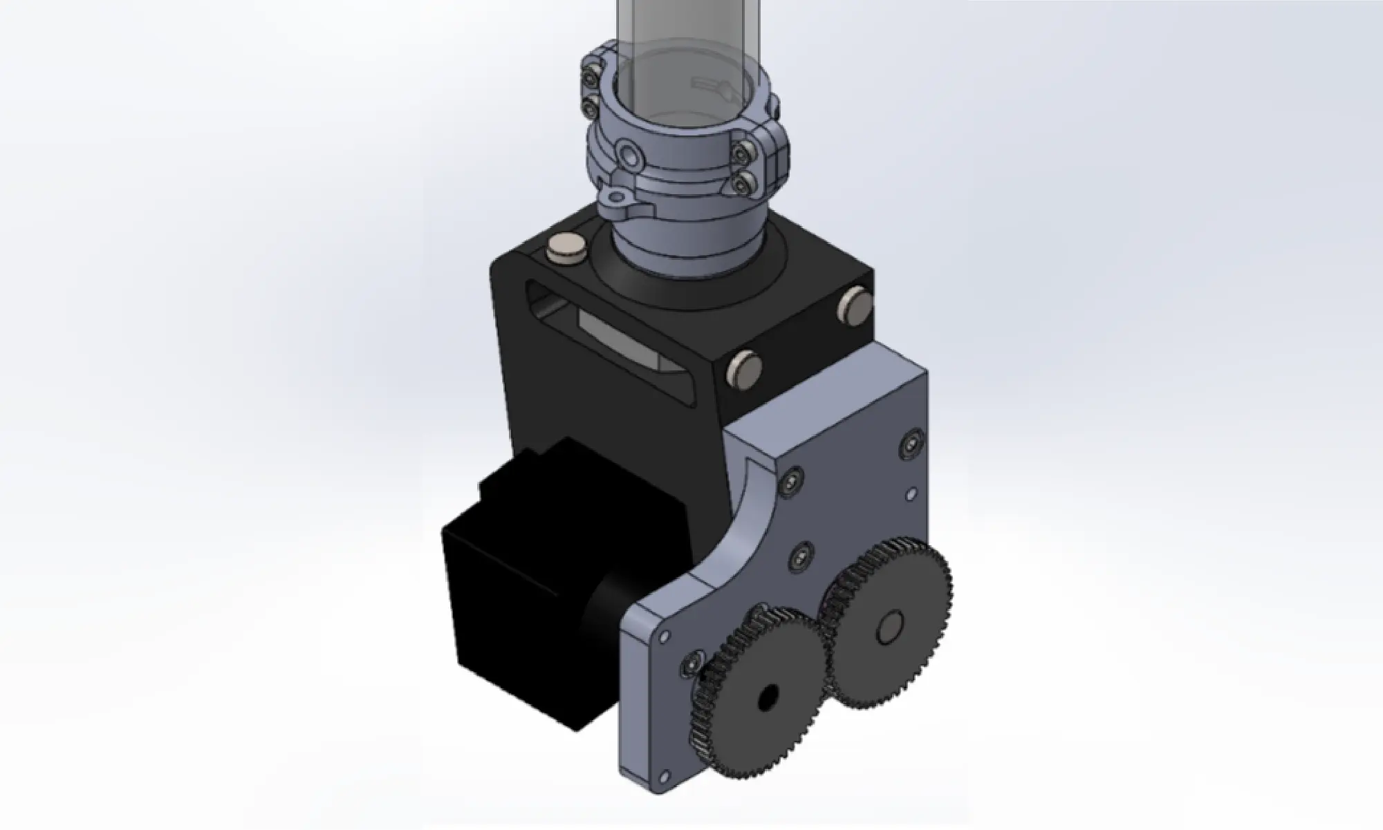
At the other end of the extruder, improvements are underway to improve the reliability and consistency of material throughput. The extruder motor is connected to the extrusion screw through a jaw coupler, which uses a polymer spider interface between two hubs. If overheated or over-torqued, this spider can become deformed, potentially affecting extruder performance. This style of couple also allows for undesirable axial motion of the extruder screw. A new disc coupler is being tested with good results (Figure 4).
Throughput problems can also be caused when the feedstock (pellets or flake) bridges within the input to the extruder. This material bridging (buildup, jamming, etc) introduces inconsistencies to the flow of material into the extruder which results in underextrusion.
This is more pronounced when using feedstock with irregular morphology and low apparent density (e.g. granulated water bottles), which do not pack tightly or flow well into the extruder under gravity alone.
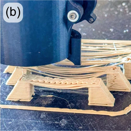
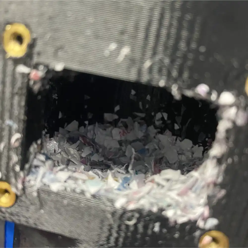
To address this, over 40 versions of a “crammer” that actively feeds material into the extruder have been tested over the years, with the current version called the “beta” crammer (Figure 5). This crammer successfully reduced inconsistencies in the extrusion rate, successfully printing rPET flake at the same rate as rPET pellet. While the crammer showed great potential for printing with irregular flake, unfortunately material bridging still happened upstream from the crammer (at the hopper-hose and hose-barb connections). To take full advantage of the crammer’s abilities, it is important to design a system to reliably resolve material bridging in the feed tube.
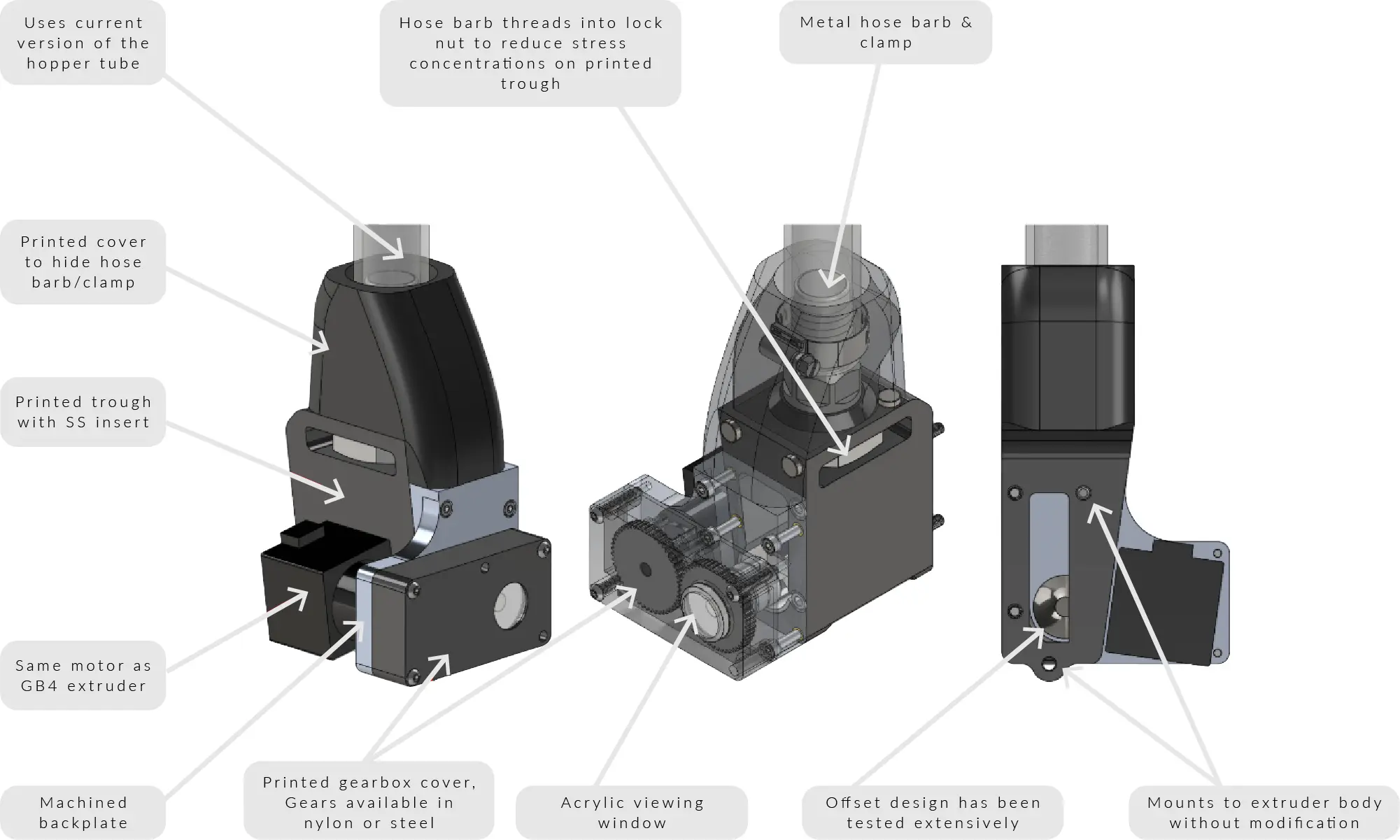
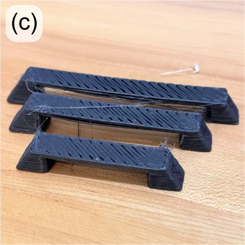
The most important recent design change to the crammer has been to the feedstock hose clamping mechanism. The tubing was originally connected using a metal hose barb and a worm gear hose clamp, similar to garden hoses. Because the hose barb fits inside the hose, the diameter of the feed path decreases at the interface, creating a stepped region that is very prone to material buildup. To address this issue, the hose barb has been replaced with two printed parts that secure the hose from the outside using screws (Figure 6). The new hose clamp design has been tested for well over 100 hours, and showed zero cases of material bridging with all pellets and most flake feedstocks. The flakes that still showed some trouble, including granulated plastic ID cards and shredded water bottles, had particularly irregular morphology due to its original thin thickness.
For feedstocks with more extreme morphologies, multiple solutions have been considered, including fluidized beds and vibration motors.
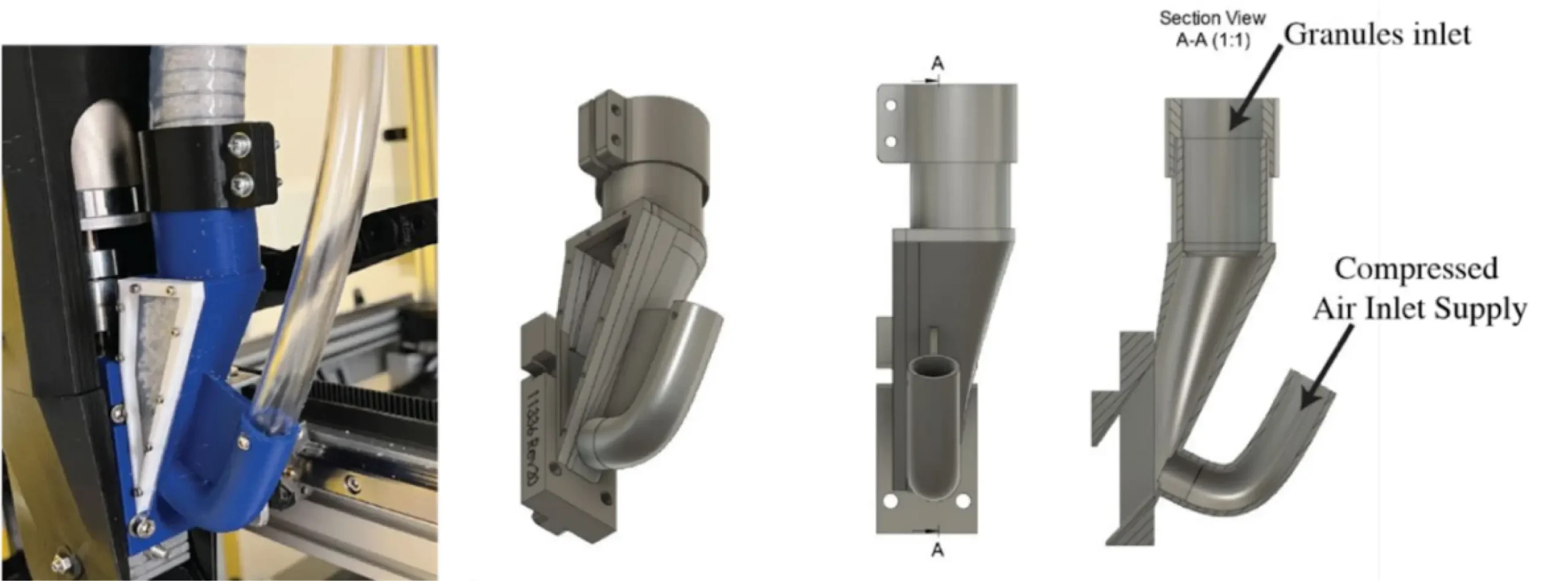
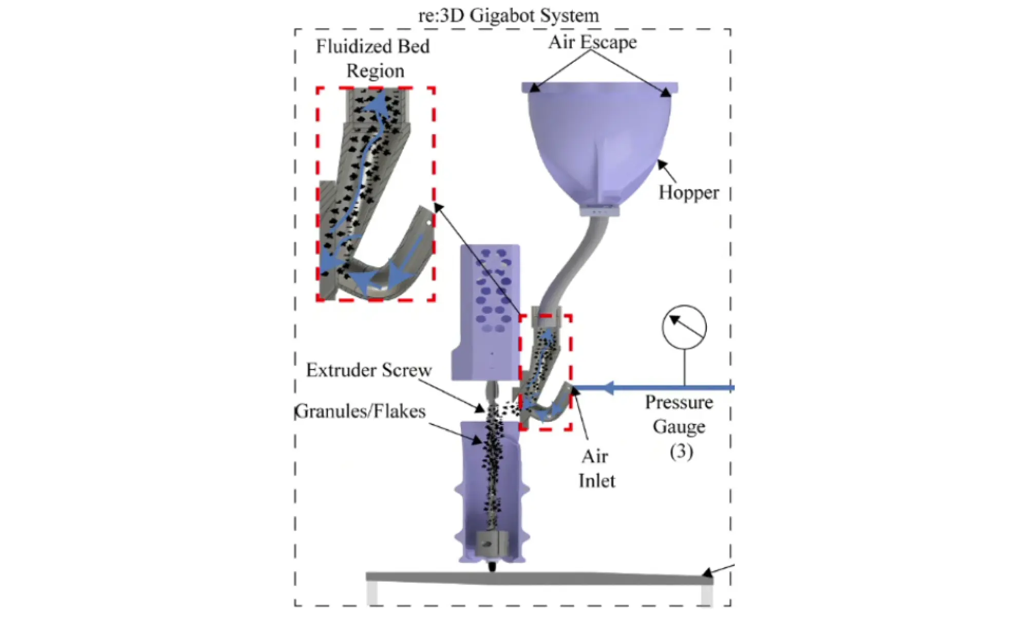
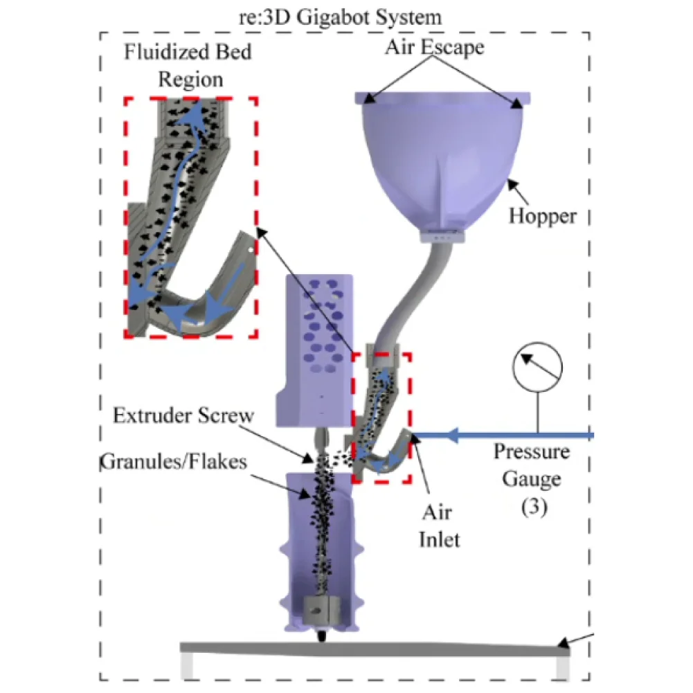
The fluidized bed system designed by Dr. Christopher Pannier’s team at the University of Michigan-Dearborn [1] sends compressed air upstream from the feed throat (Figures 7 and 8). With the right combination of air pressure and flow rate, it is possible to create an environment where solid particles behave like a fluid – a “fluidized bed”. Under this condition, flakes can flow freely through the path without building up on top of each other. Dr. Pannier’s team has tested this system to identify appropriate combinations of air pressure, air flow rate, and duty cycle that produce ideal fluidized bed conditions. However, as of today, only one material of controlled sizes (granulated rPLA, sifted 2~3mm) has been tested. To replicate similar results and identify combinations of parameters for other materials and feedstock morphologies, extensive testing is required.
Another option to reduce bridging is simply attaching one or more motors to the feed tube, generating vibrations or impact to remove buildups. There have been previous investigations into this solution at re:3D between 2021 and 2022, but the team faced issues including vibration-induced fatigue failures in wires and the printed feed throat. Eventually, this idea was abandoned as the team started to focus on the development of the crammer, which increased the throughput of the machine considerably. The vibration motor system helped with the consistency in extrusion rate by breaking up material buildup, but had little to no effect on the extrusion throughput. The vibration motor system could potentially be a great partner for the current crammer system, as they complement each other and address separate issues. The vibration motor system is not only a simple and cheap implementation, but also does not require major modifications to existing parts.
In a recent re-investigation of the vibration motor system, the motor was mounted directly onto the hose – independent from the extruder body or the crammer – such that the vibrations do not affect other systems negatively. Because constant operation of the motor may cause overheating and also accelerate vibration-induced fatigue, the motor was operated with a duty cycle using custom G-code or external python scripts. Quick testing showed promise, as even short bursts successfully broke up any material buildup along the hose. While no quantitative tests were conducted, the effect of vibrations were easily visible through the transparent feed tubing and also on the printed parts that lacked telltale signs of bridging-induced underextrusion (Figure 9). For the vibration motor system to be implemented, it will require a more robust mount design that reduces the noise (currently 50-60 dB) and secures the motor while sustaining vibrations over an extended period of printing time.
For now, a few minor tweaks to the ‘beta’ crammer have resulted in reliable and consistent extrusion performance for most feedstock materials and morphologies. But it’s good to have experience with additional options should the need for additional bridging mitigation arise.
The software team at re:3D is incredible. Their most recent work to improve customer experience with the Gigabot and GigabotX printers includes bed mesh compensation, the new Klipper stack V0.5.0, improved print recovery, and a new web application: Helm.
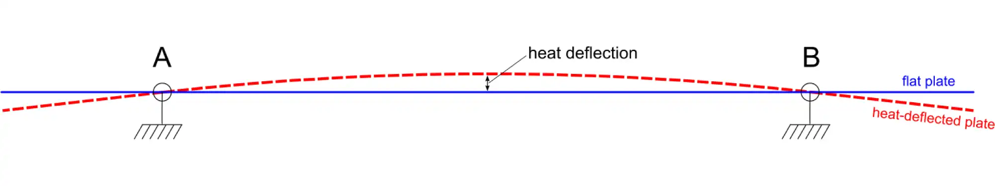
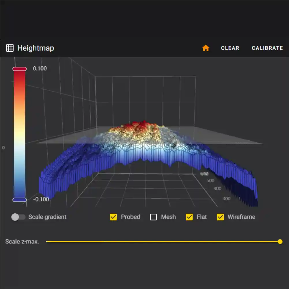
Reliable printing requires reliable, high-quality first-layers. One key factor to a successful first layer is proper bed leveling, or more properly, bed tramming. Manually leveling the large print beds on the Gigabot and GigabotX printers might take a bit of practice, but the system does remain stable – until heat is applied. When materials (especially metals) heat up, they tend to expand. Depending on the mechanical constraints on the object, its shape will change. In the case of a flat metal plate with fixed constraints as shown in Figure 10, heating a print bed can cause bowling or warping at these elevated temperatures. No matter how much you try to “level” the bed, the print nozzle will not remain a constant distance from the bed surface without active correction.
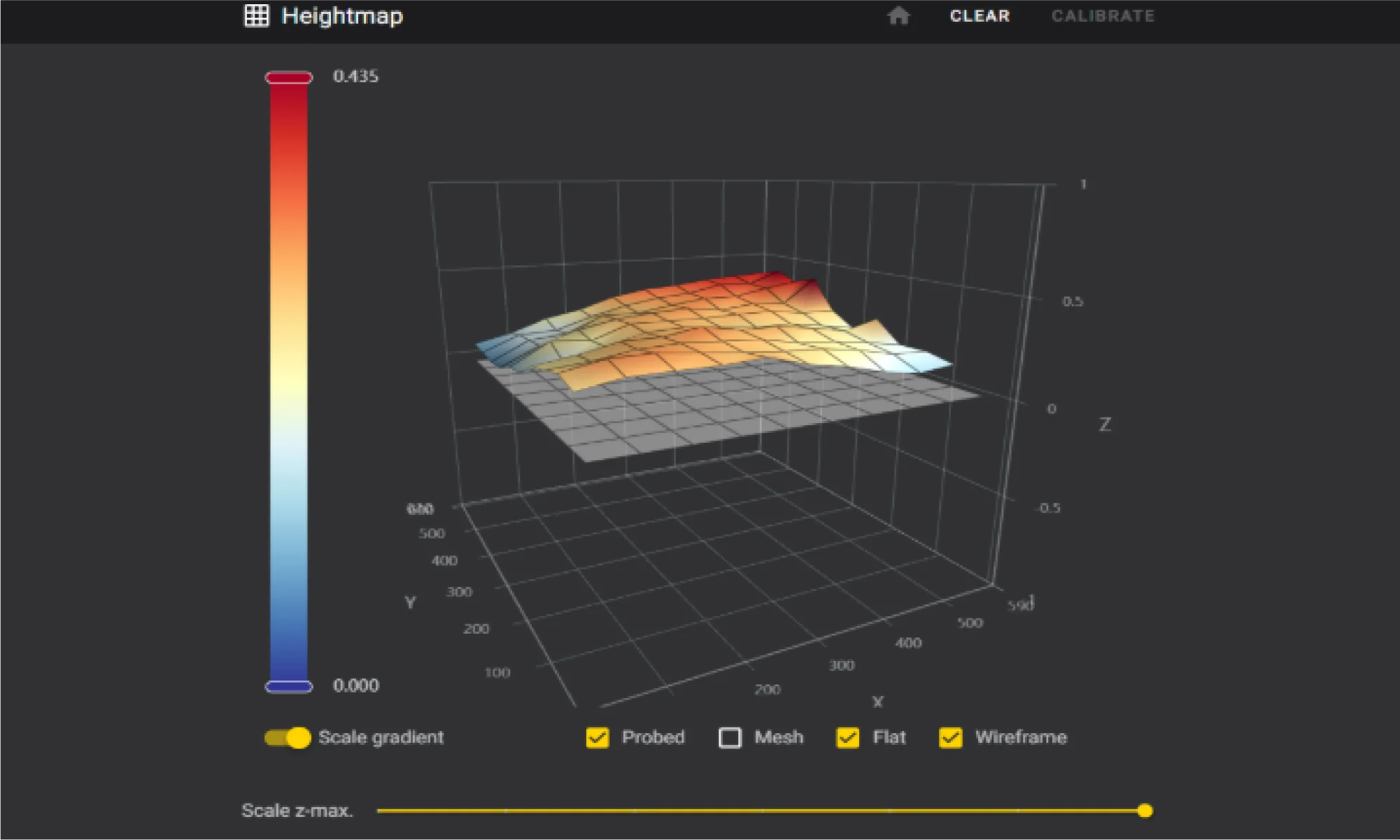
Enter “mesh compensation”. In this method, a map, or mesh, of the now-warped bed is measured with a sensor. This heightmap (Figure 11) can then be used in a mathematical algorithm to correct for changes in distance between the nozzle tip and the bed surface, and the firmware will automatically adjust the z-axis height to maintain the appropriate “height”, leading to improved first-layer adhesion, consistency and overall quality.

The team has been working hard to perfect mesh compensation to ensure it’s ready for release. An eddy current scanner was selected for its high precision, performance, and rapid data collection. Despite the clear benefits, the scanner’s reliability was a concern for users. Disconnections during a print would trigger an error and cause the print to fail, as the scanner is recognized as a main control unit (MCU), and Klipper naturally shuts down when an MCU is unresponsive or disconnected. During initial beta testing, about 33% of machines experienced these disconnections, which was consistent with in-house testing.
The software team conducted thorough investigations with the manufacturer and explored how Klipper handles MCUs – ultimately deciding to implement a feature in Klipper to declare and allow non-critical MCUs. This change prevents print stoppage if a disconnection occurs, as the scanner is not essential during an ongoing print. After this adjustment there were significant improvements in testing. This enhancement ensures that mesh compensation is not only accurate but also reliable, laying the groundwork for its upcoming release.
The release of Klipper stack V0.5.0 was delayed in 2024 due to the move but is now available to download from re:3D’s Github repository. This update introduces fine-tuning for machine parameters, new features, and fixes for existing issues. Currently, the process involves building the operating system, configuring dependencies, and settings, and then creating a copy of the entire OS, which is compressed into an image file for SD card deployment. This method is slow and cumbersome, requiring a near-perfect system state before imaging.
While the Klipper configurations are stored in a GitHub repository, allowing remote updates for machine configurations, system component updates are not possible remotely. V0.5.0 extends the ability to modify certain components, but system-wide modifications remain out of reach. The best approach may be a shift to variant creation of the distribution that grants total control over the OS and its dependencies. This would enable nightly builds and allow every system component to be modified remotely.
There has also been a lot of work improving the print recovery workflow. The current recovery tool, while useful, requires manual efforts and often results in noticeable layer artifacts. The new method, which is native to the Klipper stack, is fully autonomous and more accurate. It monitors a print in progress, constantly recording the current position of the G-code file by byte. If a stoppage occurs due to an error or other causes, the file is automatically copied and parsed to the exact last G-code line, while preserving the start G-code. This ensures that the print resumes exactly where it left off without creating a layer artifact. This new print recovery feature will significantly reduce the need for manual intervention, making the printing process smoother and more reliable.
The only caveat is that this method doesn’t cover power interruptions. To recover from a power outage, an uninterruptible power supply (UPS) would be required to send a signal to the printer’s Raspberry Pi, triggering a script when a power failure is detected.
Managing multiple printers in the factory was becoming a challenge, so re:3D’s lead software engineer developed a simple script to query devices on the network and find connected printers. This script has now evolved into a full-fledged web application for printer fleet management, aptly named Helm. Helm offers many features to enhance monitoring and synchronous communication across the network.
Helm is similar to Mainsail in that it uses the Moonraker API to communicate with Klipper, but it automatically detects Klipper printers on the network and displays detailed, dynamic information on a single page (Figure 12).
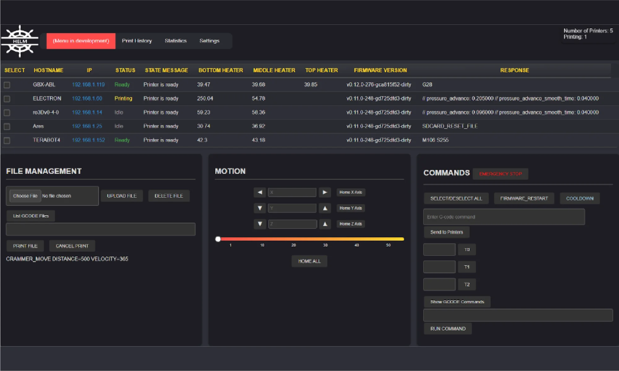
Here are some of Helm’s key features:
Helm is still a work in progress, but it’s an open-source project and open to contributions. You can try the application yourself, report problems, contribute, or follow progress here: Helm on GitHub. Helm is designed to simplify printer management and will continue to evolve with input from the community, ensuring it meets the needs of users managing multiple printers.
re:3D is proud to have a robust R&D program, sponsored in part through industry and government awards and contracts. Each of these could consume its own blog post (and perhaps someday will, disclosure rules permitting). For now, here’s a brief summary of recent and ongoing programs re:3D is engaged with through the Department of Defense, NASA, the Department of Energy and the National Science Foundation.
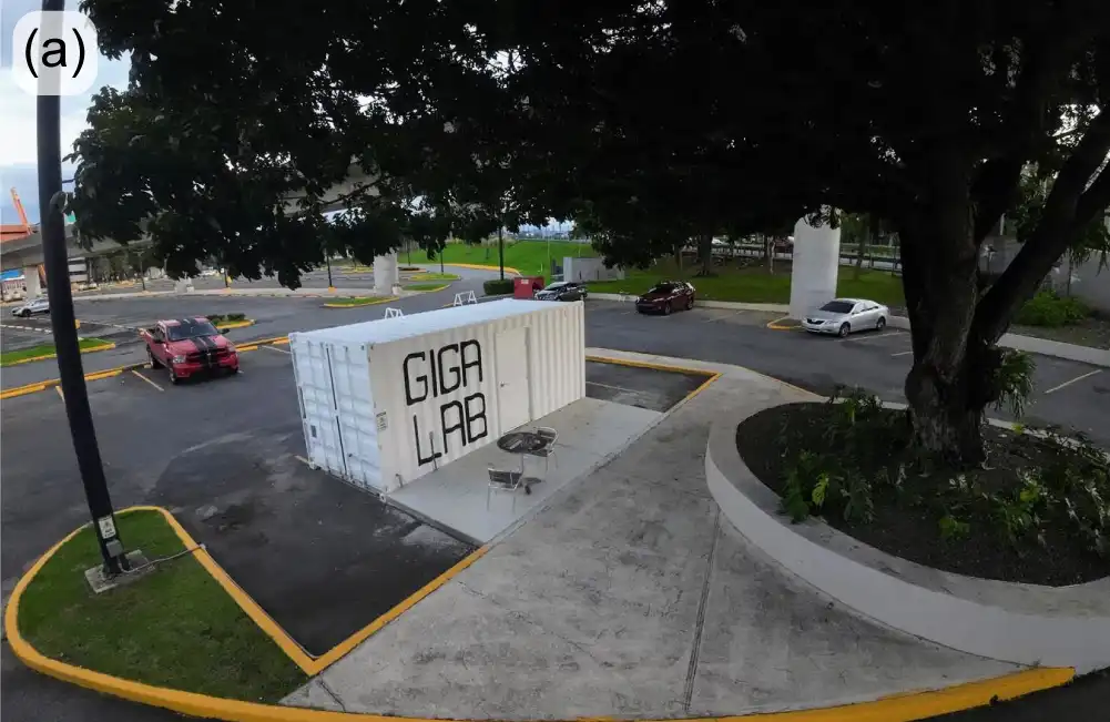
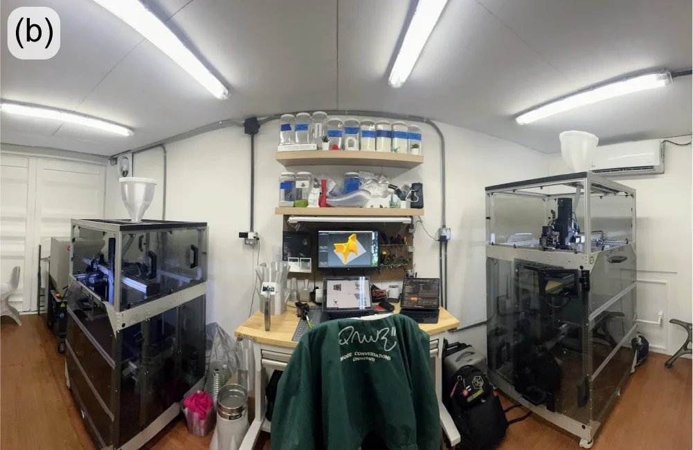
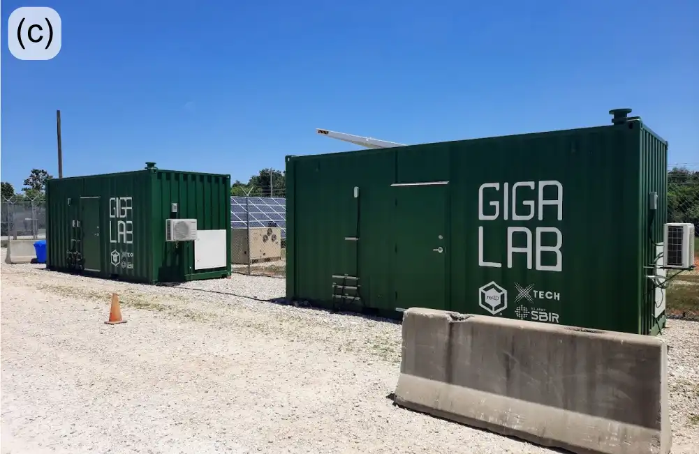
One of the visions of re:3D’s founders was to provide a means of production to people in need, who could fabricate parts from local and salvaged materials. The Gigalab is a huge step towards fulfilling that vision. Within a modified 20-ft shipping container, the Gigalab Mobile Recycling Facility can contain all of the equipment required to break down waste plastics to use as feedstock for printing functional items with a GigabotX printer. Multiple variants of Gigalabs have now been fielded at four locations: the Engine-4 coworking lab in Bayamón, Puerto Rico; an Army Corp of Engineers facility at Fort Leonard Wood, Missouri; Cannon Air Force Base in New Mexico; the Austin Habitat for Humanity ReStore location in Austin, Texas (Figure 13).
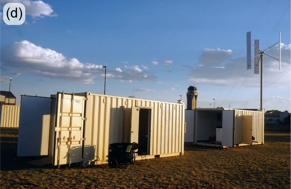
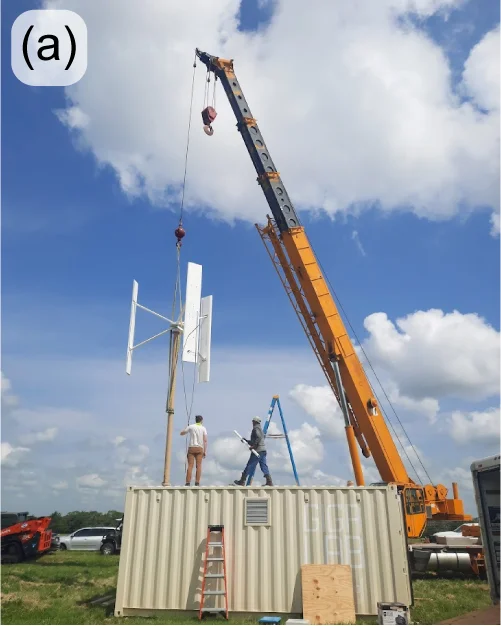
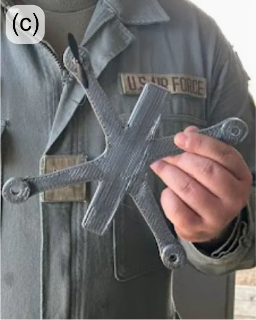
You can learn more about re:3D’s Gigalab at Engine-4 in Puerto Rico in an earlier re:3D blog post here: October 2023. Last year’s highlights from the US Army and US Air Force Gigalab projects included logistics challenges, travel to Los Angeles to install a custom energy-management system and fabricating (and flying) small drones printed from recycled drones (Figure 14).
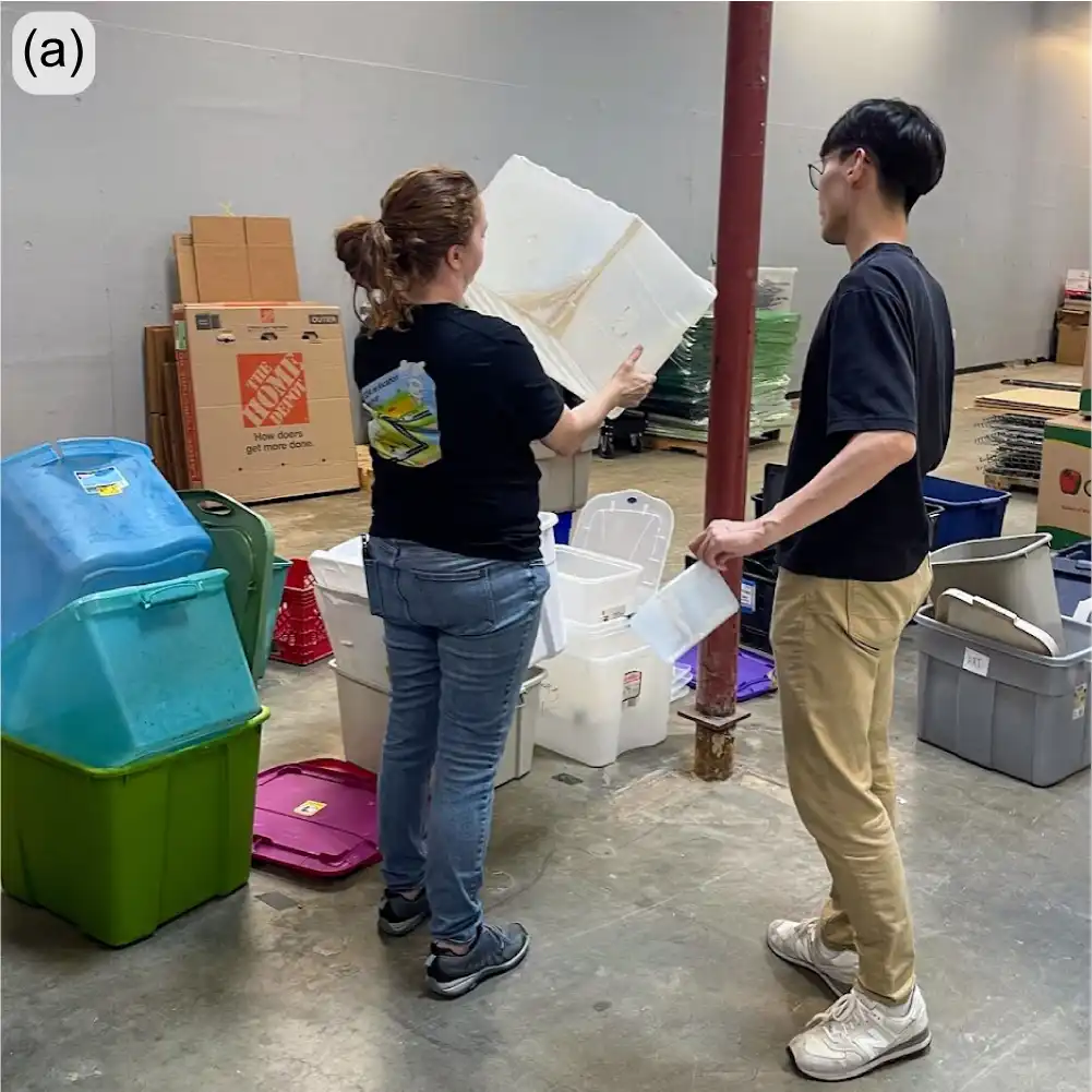
ReCreateIt is a multinational collaboration led by re:3D to transform waste plastic into valuable products with 3D printing and community-led design. The Gigalab located at the Austin Habitat for Humanity ReStore is a part of this program, which is funded through the National Science Foundation’s Convergence Accelerator. In order to maximize the value of “trash-to-treasure” in converting waste thermoplastics collected at the ReStore into printed goods of value, re:3D now employs a polymer scientist dedicated to this project who will investigate and optimize the processing and printing parameters to best recycle plastics via material extrusion additive manufacturing (3D printing).
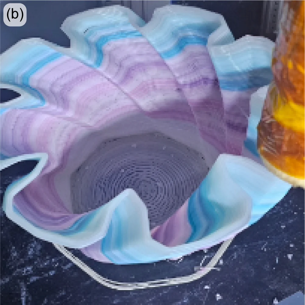
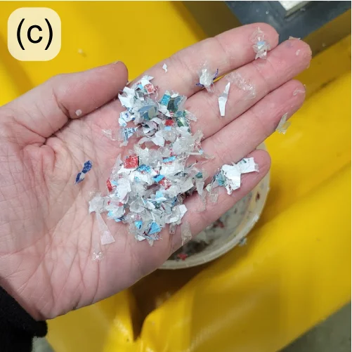
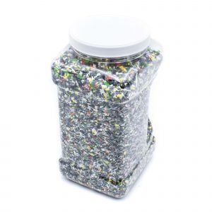
Recent success in 3D printing with recycled polypropylene (PP) is evidence of the benefit of having a polymer scientist on staff. PP is the second most widely produced plastic in the world, and is commonly used for consumer items, including storage bins, which are available in large numbers for recycling at the ReStore (Figure 15(left)). However, PP is commercially recycled at a rate of less than 5% – partly due to industrial processing and economic challenges. Additionally, as with all members of the polyolefin family of polymers, it is notoriously difficult to use as a feedstock in 3D printing, even in a neat or virgin state, let alone as recycled granulate. But the perseverance and dedication of the ReCreateIt team is paying off as evidenced by the printed vase in Figure 15(right), along with many other great successes.
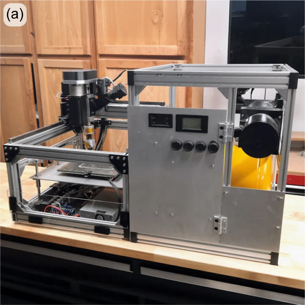
Remember the Gigalab – a converted 20-ft shipping container with the equipment to granulate plastics and print objects of use? Now imagine a similar system the size of a dorm refrigerator that uses half the power of a common space heater and is designed to work in space. This is the objective of a research contract re:3D was awarded through NASA for the Artemis Gateway program. The GigabotX has been repackaged into a low size, weight, and power (SWaP) version and integrated with a custom granulator (Figure 16(left). The system is intended to recycle packing foams which are necessary to protect payloads during liftoff, but are largely unnecessary once in space – or on the lunar or Martian surface. These foams can then be recycled for repair parts, construction materials or other items which would otherwise need to be delivered separately (at significant cost). The system isn’t ready for flight testing yet, but interim hardware demonstrations have already been performed for NASA on-site at Kennedy Space Center in Florida.
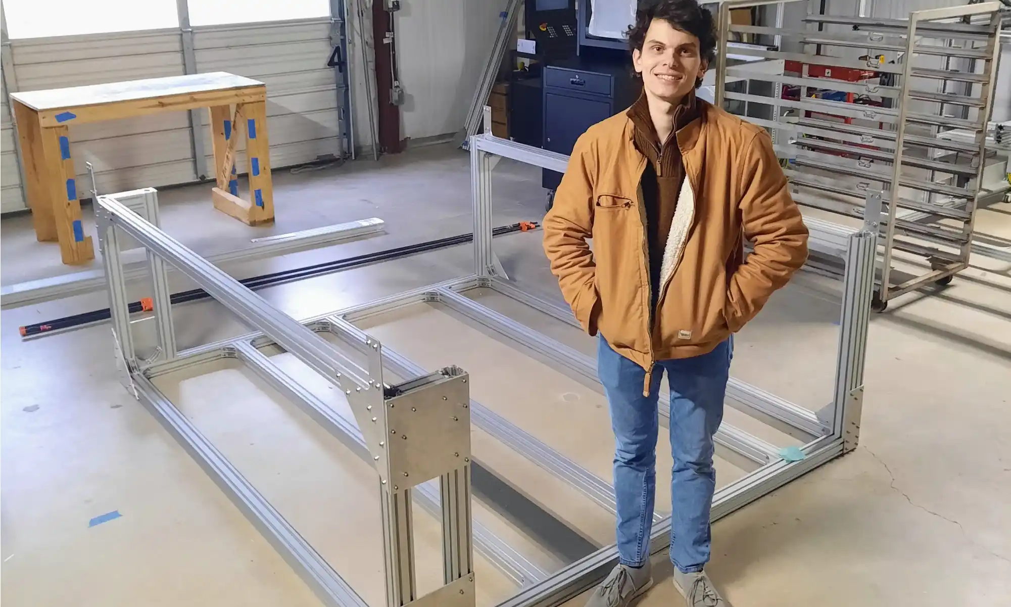
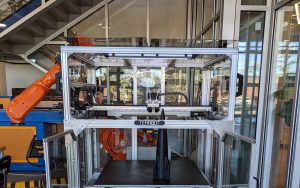
Building on the success of one of re:3D’s R&D contract with the US Army to demonstrate printing from waste in a Gigalab, sequential funding was secured to print bigger, better and faster – using a wider range of recycled materials as feedstock. This will still be a cartesian FGF printer built on an extrusion frame, but larger in footprint than re:3D’s TerabotX (Figure 17). The extrusions are larger and stiffer, and the design is more easily scalable in the length axis to accommodate future development goals. The bed will be stationary with better access from the front and back to aid print monitoring and removal. For motion control, stepper motors are being replaced with servo motors for improved speed and torque performance, and linear screws are replacing belt drives for translation. The standard ArchiMajor control board will still be used, but a custom breakout board has been designed in-house to provide servo motor control, and the Klipper GUI interface is getting an upgrade to better reflect the operation of an FGF printer.
re:3D is very pleased to collaborate with Dr. David Kazmer and his team at the University of Massachusetts Lowell to design, fabricate and optimize a new extruder with a novel screw for this project. The extruder length won’t change much from the existing GBX design, but the screw’s diameter will double and provide a very significant increase in throughput. Additional support is coming from the University of Maine’s Advanced Structures and Composites Center (ASCC). They will be leading the effort to develop recycled biocompounds – that is, feedstock materials produced from recycled polymers and wood or paper waste. This is an exciting R&D project with many possibilities for cross-development into re:3D’s portfolio of standard printers and other collaborative opportunities.
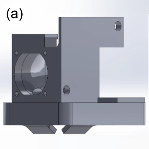
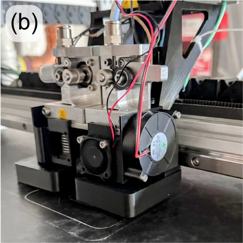
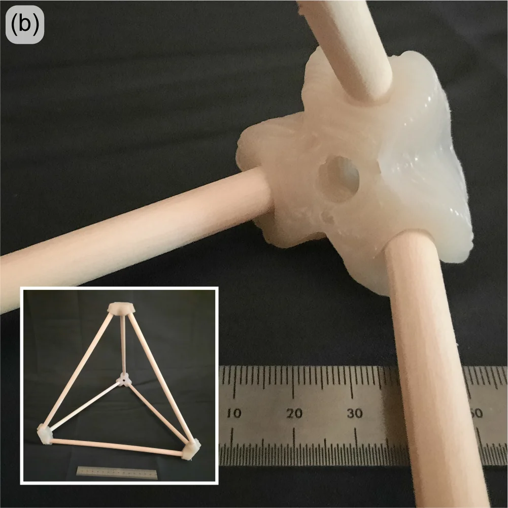
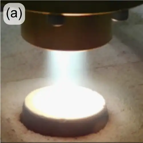
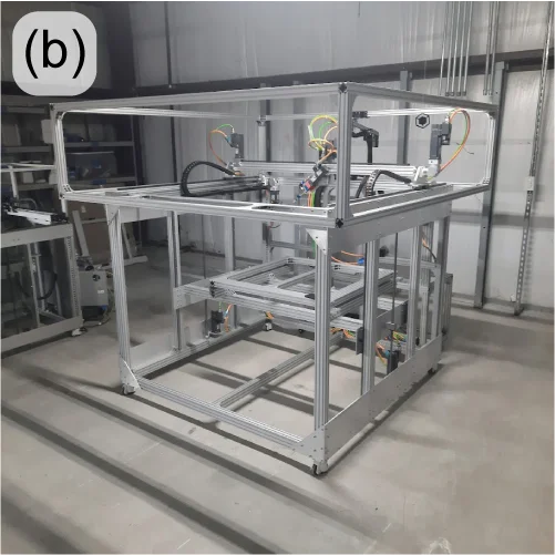
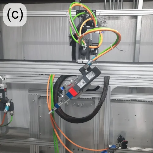
When a spacecraft enters a planet’s atmosphere, friction generates extreme heat which can damage the craft and payload (human crew or otherwise). Thermal Protection Systems (TPS) are materials designed to insulate and dissipate that heat energy – often through charring and re-radiation. Under an R&D contract with NASA / Johnson Space Center, re:3D is developing a pilot manufacturing system to print TPS materials directly onto spacecraft heatshields and other structures. Dr. Brett Compton and Dr. Damiano Bacerella (University of Tennessee – Knoxville) are developing and testing a phenolic-based foam, which when cured at elevated temperatures forms a ceramic-like TPS structure (Figure 18(a)). re:3D, in turn, is designing and building a printer to deposit the foam onto a large, non-planar aluminum dish. This requires a 5-axis printer with advanced controls (Figure 18(b-c)). re:3D is collaborating with Siemens/CATCH on the industrial motion control system, and with Addiguru for deposition monitoring.
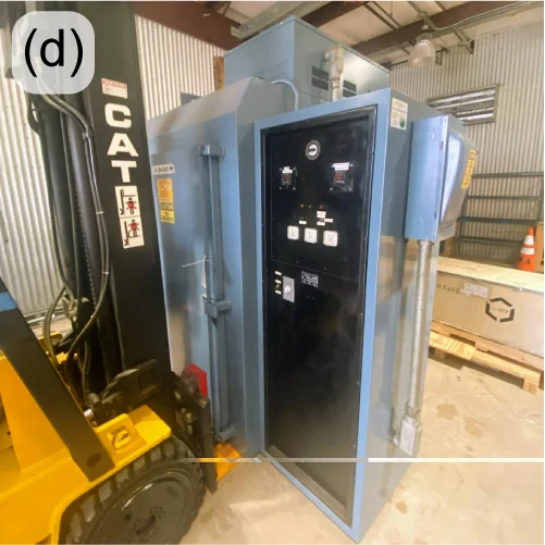
Besides the unique opportunity to work on #supercoolNASAstuff, this project is giving re:3D additional experience with new industrial control systems, 5-axis tool-path planning and printing thermoset materials. Thermosets differ from thermoplastics in that they start out in some fluid form and require heat to harden (rather than just melting and recooling, as do thermoplastics). This gained experience with thermosets will allow re:3D to provide new opportunities to work with customers on a wider range of material extrusion projects. The deposition monitoring system being spearheaded by Addiguru may also be modified for future inclusion in re:3D’s commercial products. Finally, this provided the R&D team a reason to purchase a large truck oven (Figure 18(d)) for curing the TPS foam after it is deposited onto the aluminum dish. It might also be for a dual-use on Pizza Fridays.
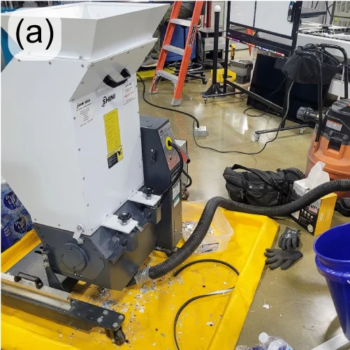
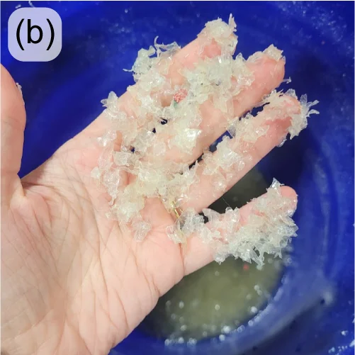
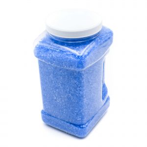
Through a Cooperative Research and Development Agreement (CRADA) with Oak Ridge National Laboratory in Tennessee, re:3D is partnering with Oak Ridge’s Manufacturing Demonstration Facility (MDF) to develop a low-cost and accessible granulator that can break down water bottles into appropriate flake (Figure 19(left)), even if they are still full of water. Collaborators at ORNL/MDF are also investigating the best ways to separate the different polymer components of the granulated water bottles (Figure 19(center, right)) so they don’t have to be pre-processed to remove the lids, safety rings and labels – often done manually in small-scale operations. Phase II of the project was approved in 2024.
This was a long post. But there was a lot to cover from last year, and it’s been awhile since an engineering update was posted to the blog. Thanks for sticking with it, and stay tuned for more (frequent) updates.
As always… Happy Printing!
References
[1] 3DBenchy.com
[2] Al Nabhani, D.; Kassab, A.; Habbal, O.; Mohanty, P.; Ayoub, G.; Pannier, C. Benchmarking the Tensile Properties of Polylactic Acid (PLA) Recycled Through Fused Granule Fabrication Additive Manufacturing. In Proceedings of the Solid Freeform Fabrication Symposium, Austin, TX, USA, 14–16 August 2023. https://doi.org/10.26153/tsw/50919
Patrick Ferrell
Senior Engineer

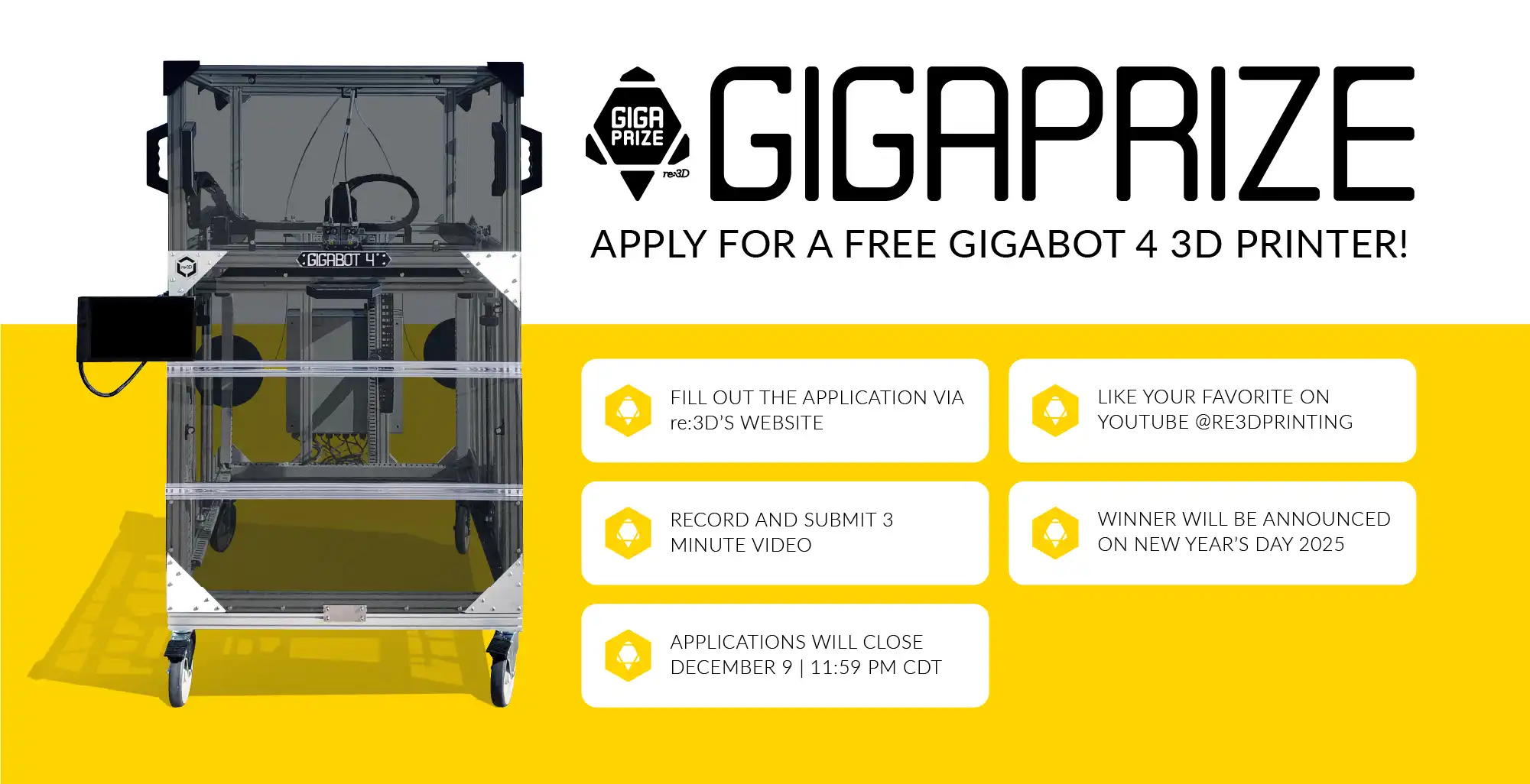
Congratulations to our 2024 Gigaprize winner – OrthoAdditive Africa in Cape Town, South Africa! OrthoAdditive Africa’s mission is to overcome barriers to healthcare access for people living with disabilities through CAD and additive manufacturing technology. They propose to use the Gigabot 4 FFF 3D printer we will be sending them to prototype a range of seating, positioning, and mobility devices currently in development with their collaborators Shonaquip.
You can learn more about their plans for Gigabot in their video:
A huge shoutout goes out to all of the outstanding applicants for this year’s prize who are doing amazing things in their communities here in the US and abroad – Asmbly Makerspace, Black Sheep Food Initiative, the Citizens Archive of Pakistan, EveryShelter, SOC Films, and the Welman Project! Entry videos for all of this year’s amazing applicants can be viewed on a dedicated playlist on our YouTube channel here.
Thank you to our amazing panel of judges for taking time out of their busy schedules to evaluate the application videos and determine the winner of this year’s Gigaprize. Please make sure to sign up for our newsletter on our website to find out when the next Gigaprize is taking place!

The Gigaprize is a competition re:3D runs to support other amazing individuals and groups committed to building community, one layer at a time. For every hundred printers we sell, we donate one Gigabot large-format, industrial filament 3D printer to an individual or organization that will use it for a good cause.
An external team of impartial judges with a wide variety of experience and expertise will evaluate applications for the Gigaprize during the second half of December. Our stellar lineup this year includes:
Our 2023 Gigaprize winner was Brookwood in Georgetown! Their vision of empowering adults with special needs with the Gigabot 4 3D printer to create art and change lives earned them this recognition.
Michael pregill
Blog Post Author

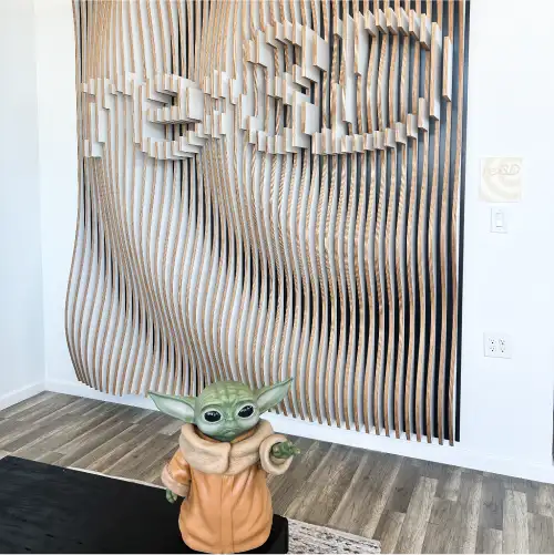
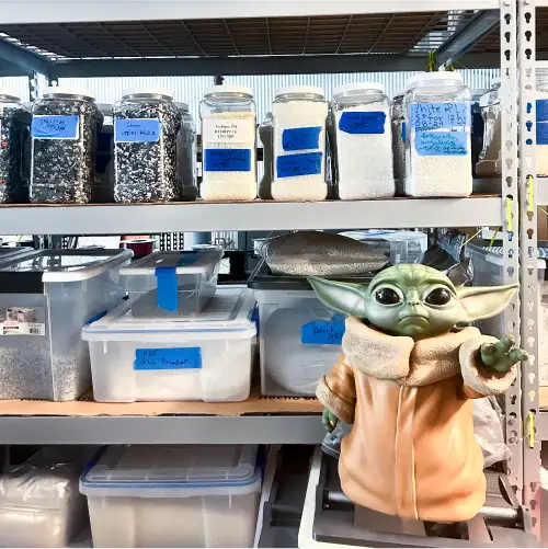
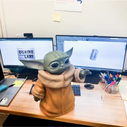
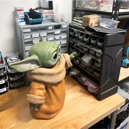
Mike Ogrinz is a maker through and through, deeply embedded in the re:3D community since backing the original Gigabot on Kickstarter in 2013. He originally purchased the Gigabot to 3D print the parts for his life-size replica of Robby the Robot. Over the years, Mike upgraded his Gigabot 2 to have a heated bed and dual-extruder capabilities. This has given Mike the ability to use the Gigabot for numerous projects, including making re:3D a life-size 3D printed Grogu (Baby Yoda) in exchange for our Series II All-Metal Body Extruder. You can read Mike’s blog post about how Grogu was created below, originally posted on his website, ogrinz.com.

I’ve had my Gigabot 3D printer for almost a decade now (wow) and every now and then the company behind it (re3D) have asked “Would you print something out for our in-house museum?” They’ve even offered to pay for the filament, shipping, etc. At one point, I *almost* sent them one of the spare heads from my Robby the Robot project, but the thought of all that sanding, priming, and painting scared me off.
Then a few months ago Jennifer from re3D reached out again. She asked if I’d be interested in making something, and even offered me some credit in their store. Well, I did have my eye on a set up fully-machined dual aluminum extruders as an upgrade for my Gigabot…. So I asked, “What would I have to make you in exchange for those parts?”
Jennifer almost immediately answered “Baby Yoda!” and the deal was struck. I figured with the filament cost probably coming in around $100, I was getting the better end of the deal. But of course, there was a lot of finish work required. And since Grogu has so many organic surfaces and details, it had to all be done by hand. I had to completely finish the replica too, which meant learning how to use an airbrush (well, it meant buying and airbrush and then learning how to use it). But I am extremely happy with how it came out. Now if I only could find the time to install those metal extruder mechanisms…
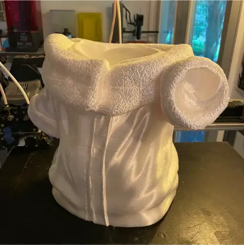
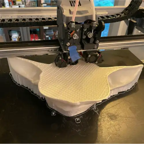

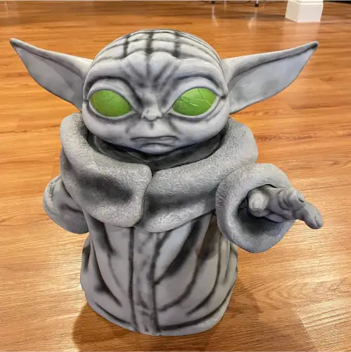
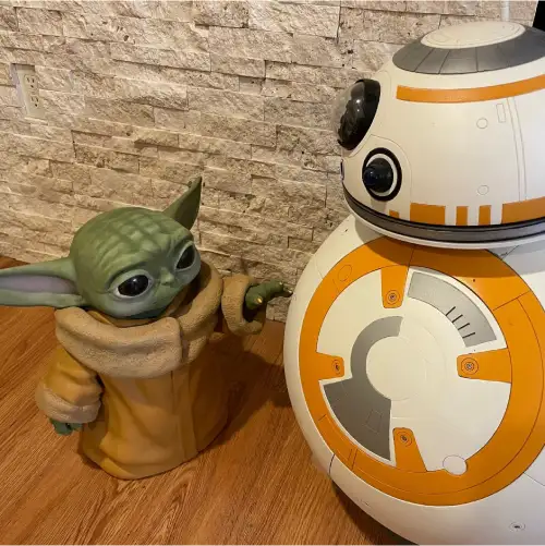
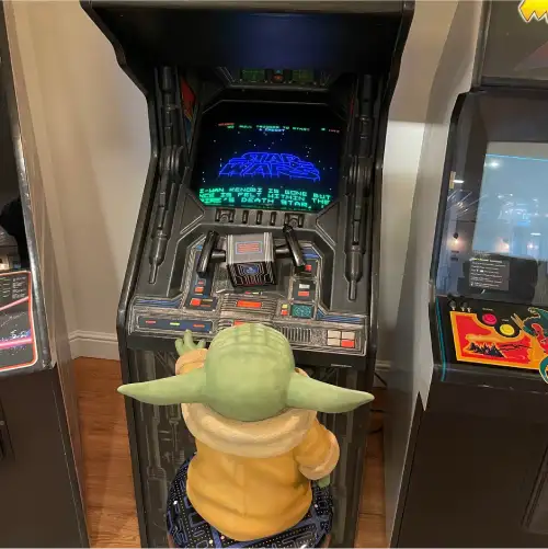

The 3D printed Grogu took 134 hours to print and used three rolls of PLA Silk filament.
The original Grogu file came from MarVin_Miniatures on Thingiverse. You can also follow them on Facebook, @MarVinMinis.
To learn more about Mike’s other projects click here. You can also check out Mike’s YouTube Channel, Ogrinz Labs, where he posts educational and informational videos on his awesome builds.
Jennifer Dennington
Blog Post Author


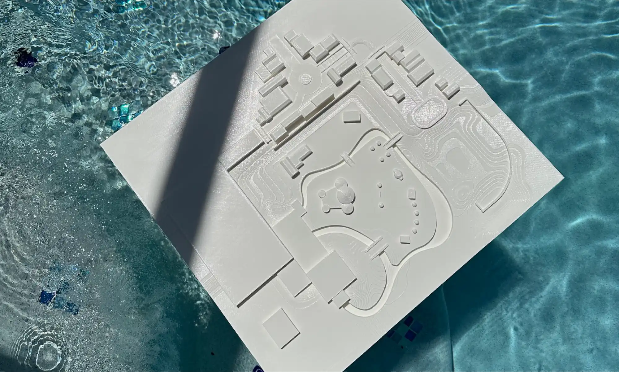
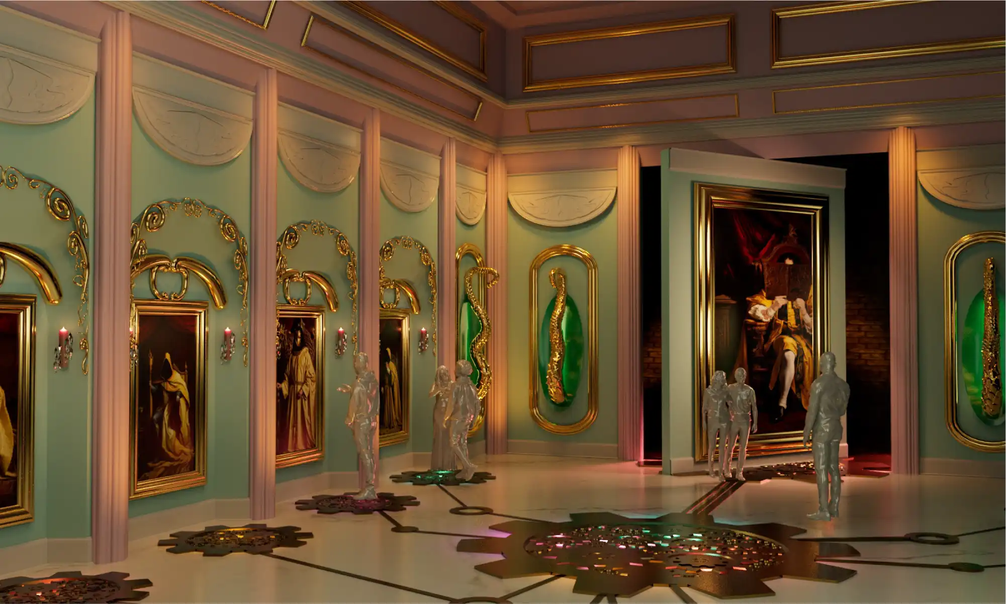
In the highly competitive realm of themed experience design, standing out requires not only innovative concepts but also the ability to present those concepts in a compelling and tangible way. This was the challenge faced by our project team at the University of Central Florida’s (UCF) Themed Experience Master’s Program. Our project, “Domain Bizarre,” aimed to revolutionize the theme park experience with a queueless land design. Key to our success was the utilization of a large-scale 3D printed massing model, generously provided by re:3D Inc.
In themed entertainment design, the devil is in the details. Traditional desktop 3D printers, while useful, often produce models that are too small to effectively convey the full scope and intricacy of a design. This is where re:3D Inc.’s large-scale 3D printing capabilities came into play, allowing us to create a 2ft x 2ft massing model of Domain Bizarre.
The ability to print a large model was crucial for several reasons:
Detailed Realism: Larger models capture finer details and provide a more realistic representation of our design. This level of detail is essential for themed entertainment, where every element contributes to the overall narrative and guest experience.
Comprehensive Visualization: A substantial model offers a more comprehensive view of the project, helping our team and the judges better understand spatial relationships, proportions, and the overall layout of Domain Bizarre.
Impactful Presentations: For our presentation, the large-scale model made a significant impact. It allowed the judges to truly grasp the scale and complexity of our design, enhancing their understanding and engagement.
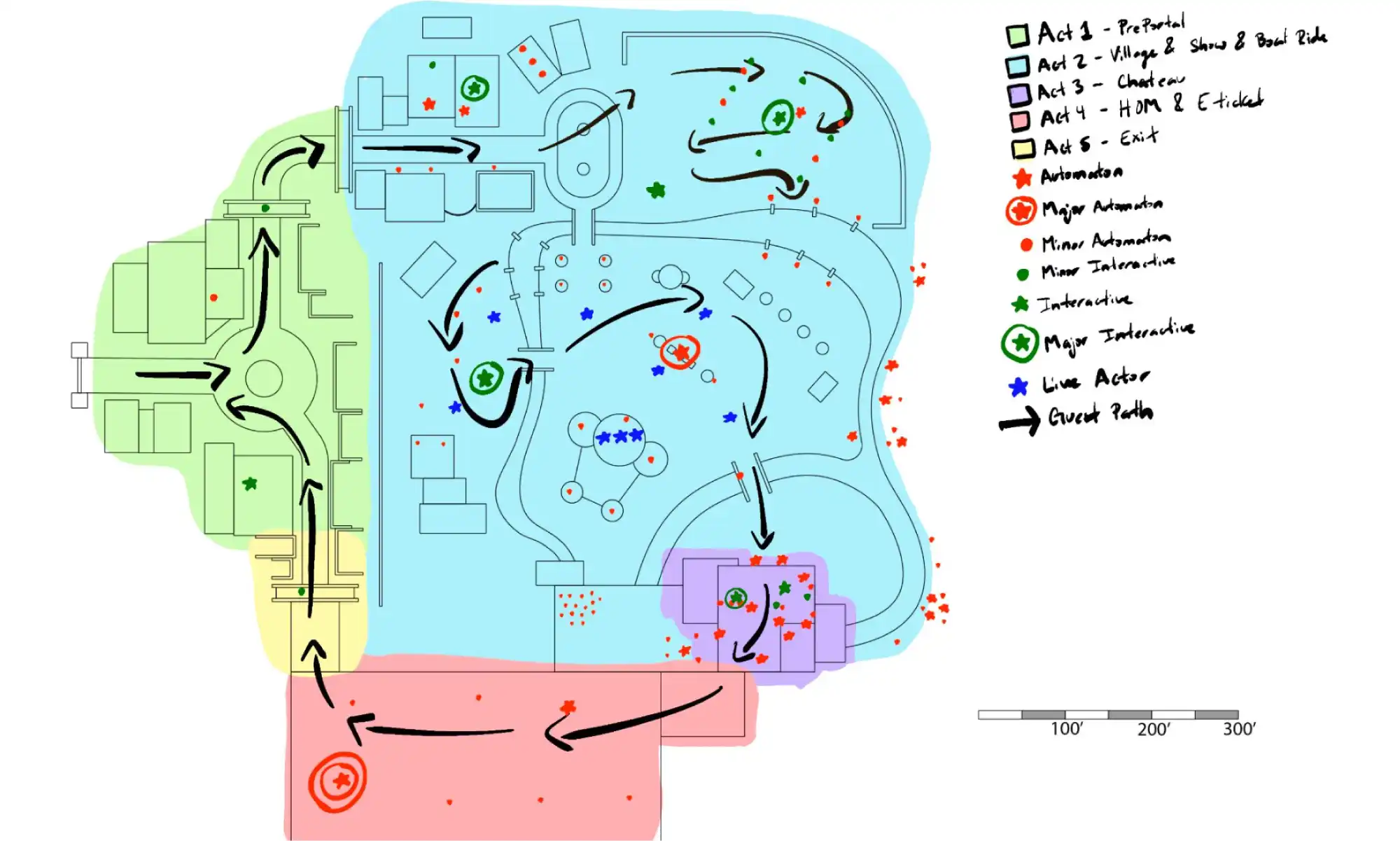
Domain Bizarre is a queueless land designed to be integrated into an existing theme park. Our goal was to create a seamless, immersive environment where guests could explore at their own pace without the constraints of traditional queues. Here’s how the large-scale 3D printed model facilitated this vision:
Design Breakdown: The 2ft x 2ft model allowed us to break down different areas of Domain Bizarre, illustrating how story beats unfolded across the land. We could clearly show where interactive elements, seating areas, and food stalls were ideally located.
Interactive Elements: By printing large, we could place and adjust interactive elements within the model, ensuring they fit seamlessly into the environment and contributed to the overall guest experience.
Optimized Layout: The detailed model helped us optimize the placement of various features, ensuring that every element—from food stalls to seating areas—was strategically placed to enhance the guest experience.
While UCF’s Themed Experience Master’s Program provided the platform for our project, it was re:3D Inc. that made our vision a reality. Their Gigabot 3D printer allowed us to create a detailed, large-scale massing model that was pivotal to our presentation’s success. The ability to “print HUGE” provided a level of detail and realism that desktop models simply cannot achieve.
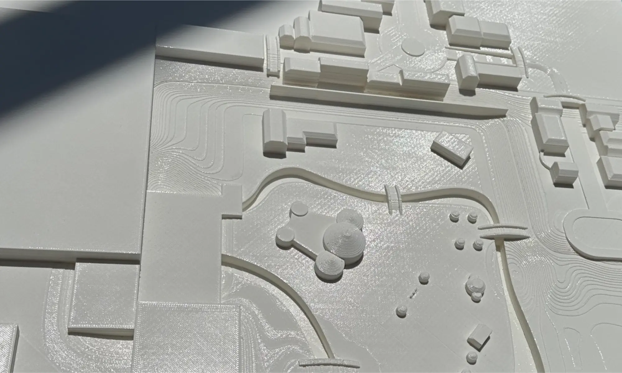
The impact of our large-scale model on the presentation was profound. Judges were able to see our world in a tangible form, allowing them to fully appreciate the intricacies and thoughtfulness of our design. The model’s size and detail made it easier for them to visualize how Domain Bizarre would function in real life, enhancing the overall effect of our presentation.
The successful presentation of Domain Bizarre demonstrates the critical role that large-scale 3D printing can play in themed experience design. By collaborating with re:3D Inc., our project team was able to create a compelling and detailed massing model that brought our vision to life. This experience underscores the importance of innovative presentation tools in the field of themed entertainment, paving the way for future projects to push the boundaries of creativity and design.
For our team, the journey of Domain Bizarre was not just about presenting a project; it was about pioneering new methods of visual storytelling and spatial design. With the help of re:3D Inc., we showcased how large-scale 3D printing can transform abstract concepts into tangible realities, setting a new standard for themed experience presentations.
Blog Post Author

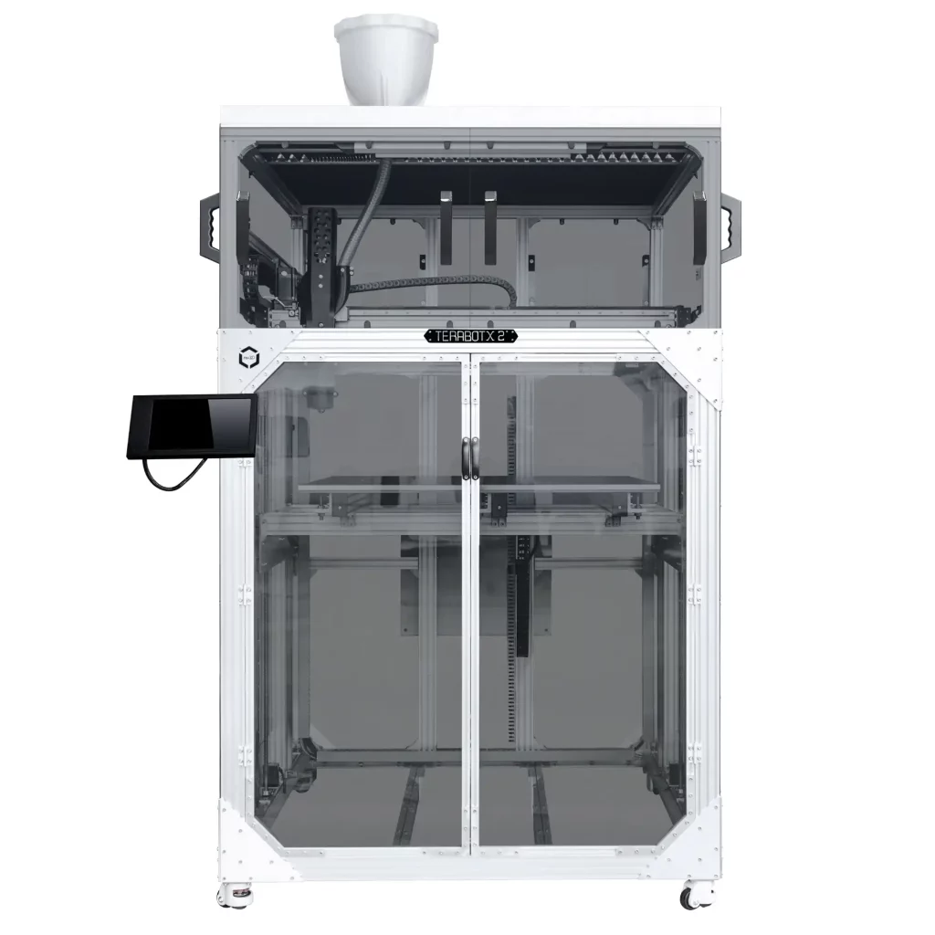
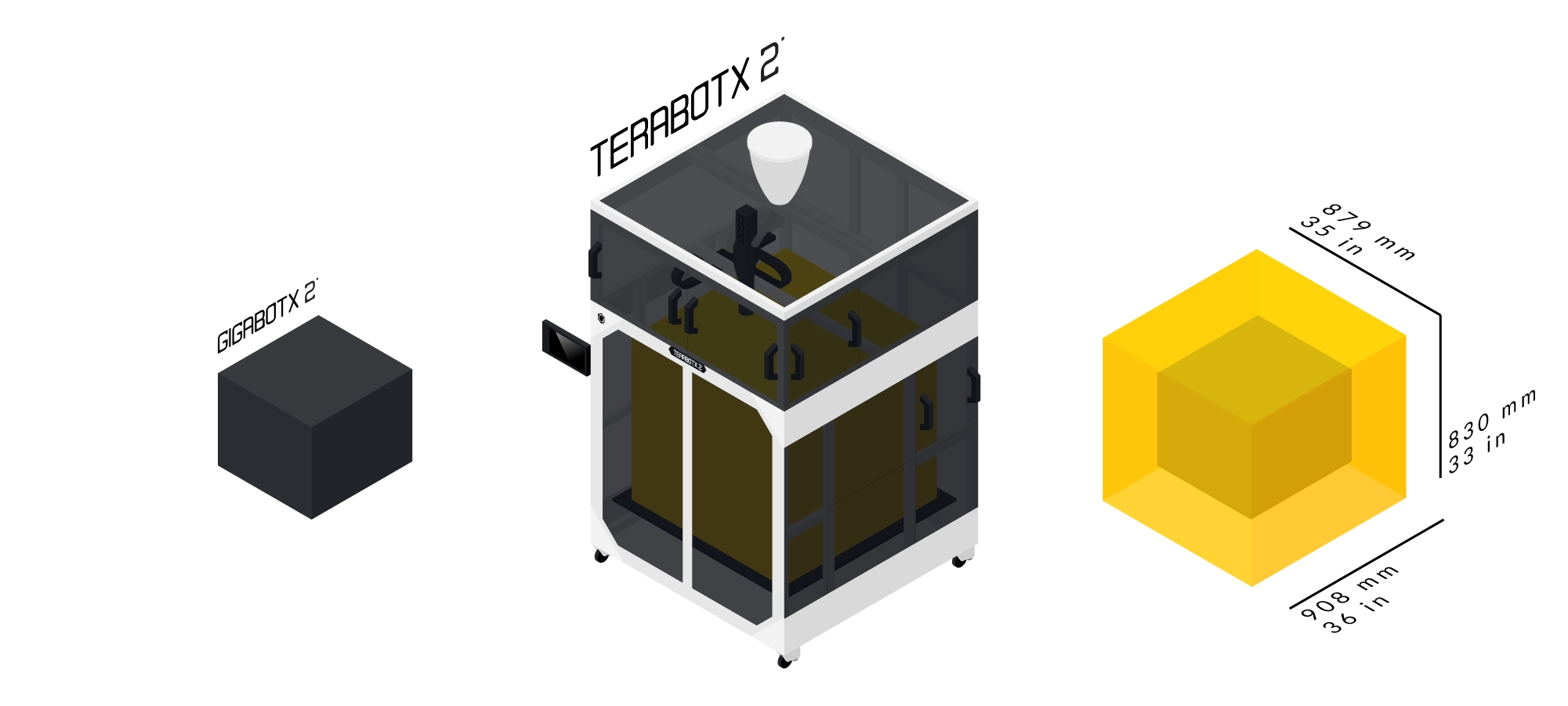
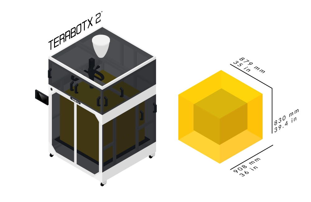
Fulfill your large-format FGF 3D printing needs with TerabotX 2, expanding the size of your build volume to 879 x 908 x 830mm. This direct-drive pellet extrusion based 3D Printer can print from virgin or recycled pellets, flake, or regrind – and bring us even closer to the dream of a circular economy.
A ⅝” extruder screw with a 16:1 L/D ratio powered by a NEMA 23 motor enables 3D printing with 3-5mm plastic granules with melting temperatures below 270ºC. With a larger 0.4, 0.8, 1.75 or 3mm nozzle, TerabotX 2 3D printer reduces the dependence on printing with filament while supporting plastic granule mixing, increasing printing speed and cost savings.
Your open-source industrial 3D printer is powered by a 32bit Ultimachine ArchiMajor control board and Klipper firmware run on a Raspberry Pi. Access TerabotX 2 controls via the Mainsail interface on either the 10” LCD touchscreen or a desktop or mobile web browser.
Hand-crafted in Texas by team re:3D to highly precise standards, your TerabotX 2 3D printer is modular, upgradable and backed by Lifetime Customer Support.
FGF
879 x 908 x 830 mm
Steel 5/8" extruder screw with a 16:1 L/D ratio
Supports thermoplastics melting below 270 ºC
Supports 3 - 5 mm plastic granules & pellets
0.32 - 2.25 mm
up to 30 mm/sec
0.4, 0.8, 1.75 or 3 mm
Modular & upgradable construction
Robust aluminum cartesian frame
Cast aluminum blanchard ground flat 0.5” thick build plate
NEMA 17 & 23
Full color 10" LCD Touchscreen with Mainsail for Klipper interface
Optional network connecting for local monitoring & control
USB or Wifi
Open source Klipper software stack
G-code (.gcode) upload file type
Includes Simplify3D setting profiles
110V 60Hz 20A or
220V 50Hz 10A
Up to 270ºC
Up to 115ºC


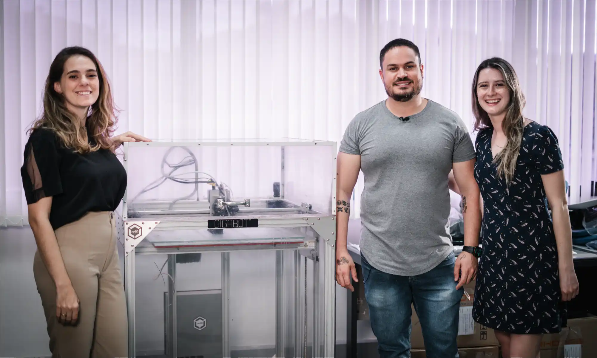
Have you ever considered how the chair you are sitting on right now was made? It’s a question that often goes overlooked in our daily lives, yet the answer reveals a world of innovation and creativity shaping the furniture industry. One of the notable players in this space is Brazilian manufacturer, Rhodes. Founded in 1964, Rhodes has been at the forefront of chair component manufacturing, producing around 5 million components annually for various seating solutions, from office chairs to public seating in airports and stadiums.
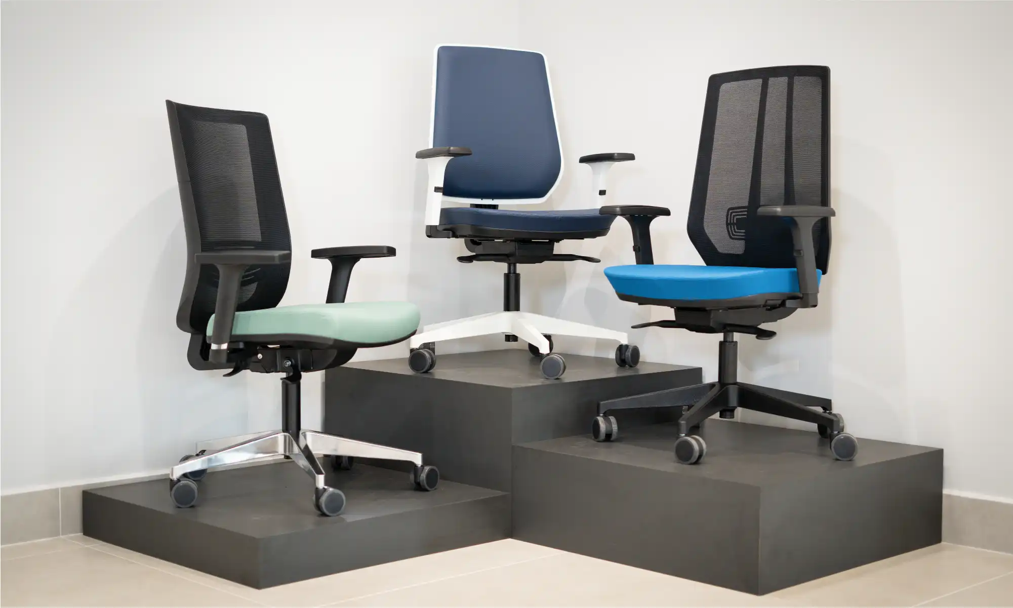
Rhodes plays a vital role in providing essential elements for operative chair lines. Key products include bases, columns, and mechanisms, which maintain Rhode’s strong presence as a component supplier. Despite market challenges, especially during Brazil’s economic crisis in 2013-2014, Rhodes has excelled. During the COVID-19 Pandemic, Rhodes expanded into the ready-made chair market, adapting to the growing need for home offices. Currently, Rhodes is a major manufacturer of chairs and chair components in Brazil and exports its products to other Latin American countries, the United States, and some parts of Europe.
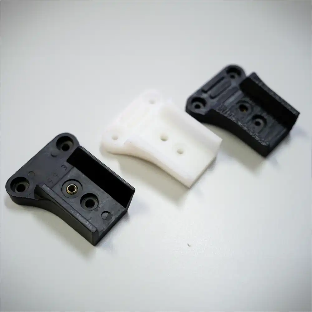
Rhodes’ integration of 3D printing played a crucial role in streamlining their manufacturing process and achieving global success. Initially, Rhodes outsourced their 3D printing needs. They would create a computer-aided design (CAD) file for their chair component prototypes, send it to a partner company in Italy, and wait for the 3D printed component to come back. The cost and time constraints prompted Rhodes to explore other alternatives. After a Google search led Rhodes to re:3D, the size and affordability of re:3D’s Gigabot cemented their purchase as Rhodes first in-house 3D printer for prototyping and design iterations. A decade later, Rhodes’ workhorse Gigabot 2 is still going strong, being used to 3D prototype every plastic component of their furniture lines.
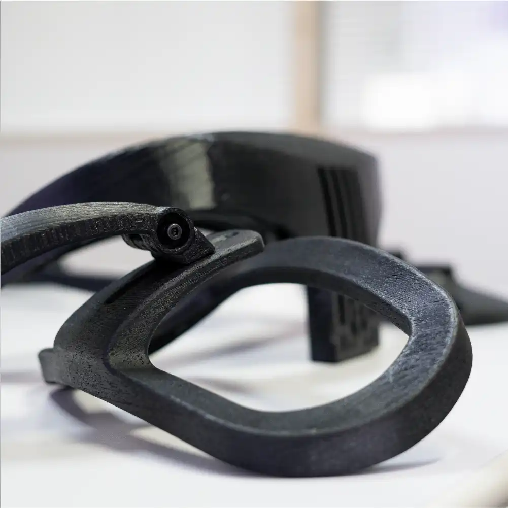
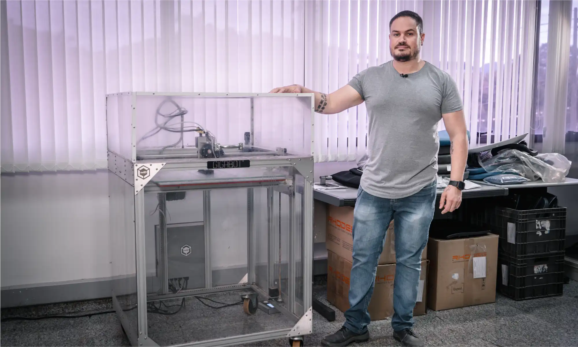
Gigabot’s robustness and versatility has allowed Rhodes to seamlessly integrate 3D printing into their development processes. From mitigating design flaws to producing quick 3D prototypes for assessment, Gigabot has been a reliable companion, functioning almost continuously for a decade. But it wasn’t always that easy. It took Júlio a full year of experimenting and learning before getting quality prints from Gigabot, since he had no prior 3D printing experience when Rhodes decided to test the technology. Julio had to determine which material to print with and find a reliable national supplier. He ended up choosing ABS because of its durability, which was key to testing the prototypes before finalizing their design. Júlio built an enclosure for the machine to overcome temperature differences during different seasons and ensure ABS would print year-round. He has also tested every type of glue on the market, including hairspray, to make the prints adhere to the print bed, as re:3D’s original Gigabot 2 did not come with PrintinZ.
Júlio started small, prototyping components of chairs such as caster bases, columns, mechanisms, seats, and backrests. Rhodes also began to use Gigabot to print replacement parts for machines in their factory and has been contracted by their vendors to CAD other non-chair-related products. Because of their success with Gigabot 2, Rhodes purchased a Gigabot 4, which will be an upgrade from their current, single-extruder workhorse. Júlio anticipates enhanced ease of use and agility, allowing for increased prototyping and quicker project timelines. Júlio believes that 3D printing’s strength and effectiveness is well-established and expects the technology to continue influencing the furniture industry.
The integration of Gigabot at Rhodes exemplifies how innovative technologies can revolutionize traditional industries. Júlio’s insights showcase the profound impact of 3D printing on Rhodes’ development processes, fostering creativity, and enabling the exploration of new design possibilities. Looking towards the future, Rhodes is poised to take its manufacturing capabilities to new heights with the upcoming addition of the Gigabot 4. With its dual-extrusion print head, this advanced 3D printer will enable Rhodes to produce larger, more intricate 3D prototypes, pushing the boundaries of design creation even further. Moreover, by doubling their printing capacity with two Gigabots, Rhodes aims to accelerate their prototyping process, allowing for quicker iteration and refinement of their chair designs. As Rhodes continues to leverage Gigabot’s capabilities, it exemplifies a story of adaptation and innovation in the furniture manufacturing industry that is not slowing down.
Você já parou para pensar em como a cadeira em que você está sentado agora foi feita? É uma pergunta que muitas vezes passa despercebida em nossas vidas diárias, mas a resposta revela um mundo de inovação e criatividade que está moldando a indústria de móveis. Um dos nomes mais fortes nesse espaço é a fabricante brasileira Rhodes. Fundada em 1964, a Rhodes tem estado na vanguarda da fabricação de componentes para cadeiras, produzindo cerca de 5 milhões de componentes anualmente para várias soluções de assentos, desde cadeiras de escritório até assentos públicos em aeroportos e estádios.
A Rhodes desempenha um papel vital no fornecimento de elementos essenciais para linhas de cadeiras operativas. Os principais produtos incluem bases, colunas e mecanismos, o que mantêm a forte presença da Rhodes como fornecedora de componentes. Apesar dos desafios do mercado, especialmente durante a crise econômica do Brasil em 2013-2014, a Rhodes se destacou. Durante a pandemia de COVID-19, a empresa expandiu seu portfólio para o mercado de cadeiras prontas, adaptando-se à crescente necessidade do home office. Atualmente, a Rhodes é uma das principais fabricantes de cadeiras e componentes para cadeiras no Brasil, além de exportar seus produtos para outros países da América Latina, Estados Unidos e algumas partes da Europa.
A integração da impressão 3D pela Rhodes desempenhou um papel crucial na otimização do seu processo de fabricação e no alcance do sucesso global. Inicialmente, a Rhodes terceirizava suas necessidades de impressão 3D. Eles criavam um arquivo de design assistido por computador (CAD) para os protótipos de componentes das cadeiras, enviavam para uma empresa parceira na Itália e aguardavam o retorno do componente impresso em 3D. Os custos e as restrições de tempo levaram a Rhodes a explorar outras alternativas. Após uma pesquisa no Google levar a Rhodes à re:3D, o tamanho e a acessibilidade do Gigabot da re:3D consolidaram a compra como a primeira impressora 3D interna da Rhodes para prototipagem e iterações de design. Uma década depois, a robusta Gigabot 2 da Rhodes ainda está em plena atividade, sendo usada para prototipar todos os componentes plásticos de suas linhas de móveis.
A robustez e a versatilidade do Gigabot permitiram à Rhodes integrar perfeitamente a impressão 3D em seus processos de desenvolvimento. Desde mitigar falhas de design até produzir protótipos rápidos para avaliação, a Gigabot tem sido uma companheira confiável, funcionando quase que continuamente por uma década. Mas nem sempre foi tão fácil. Júlio levou um ano inteiro de experimentação e aprendizado antes de conseguir impressões de qualidade com a Gigabot, já que ele não tinha experiência prévia com impressão 3D quando a Rhodes decidiu testar a tecnologia. Júlio teve que determinar qual material usar para impressão e encontrar um fornecedor nacional confiável. Ele acabou escolhendo ABS por causa de sua durabilidade, o que foi crucial para testar os protótipos antes de finalizar o design. Júlio construiu uma caixa de proteção para a máquina para superar as diferenças de temperatura durante as diferentes estações, garantindo que o ABS fosse impresso durante todo o ano. Ele também testou todos os tipos de cola no mercado, incluindo spray de cabelo, para fazer as impressões aderirem à mesa de impressão, já que o Gigabot 2 original da re:3D não vinha com a tecnologia PrintinZ.
Júlio começou pequeno, prototipando componentes de cadeiras, como bases de rodízios, colunas, mecanismos, assentos e encostos. A Rhodes também começou a usar o Gigabot para imprimir peças de reposição para máquinas em sua fábrica e foi contratada por seus fornecedores para criar em CAD outros produtos não relacionados a cadeiras. Devido ao sucesso da Gigabot 2, a Rhodes comprou uma Gigabot 4, que será uma atualização em relação ao seu robusto equipamento atual de extrusora única. Júlio prevê maior facilidade de uso e agilidade, permitindo mãos projetos de prototipagem e prazos mais curtos. Júlio acredita que a força e a eficácia da impressão 3D estão bem estabelecidas e espera que a tecnologia continue influenciando a indústria de móveis.
A integração da Gigabot na Rhodes exemplifica como tecnologias inovadoras podem revolucionar indústrias tradicionais. As percepções de Júlio mostram o profundo impacto da impressão 3D nos processos de desenvolvimento da Rhodes, promovendo a criatividade e possibilitando a exploração de novas possibilidades de design. Olhando para o futuro, a Rhodes está pronta para levar suas capacidades de fabricação a novos patamares com a próxima adição da Gigabot 4. Com sua cabeça de impressão de dupla extrusão, esta avançada impressora 3D permitirá que a Rhodes produza protótipos maiores e mais intrincados, expandindo ainda mais os limites da criação de design. Além disso, ao dobrar sua capacidade de impressão com duas Gigabots, a Rhodes visa acelerar seu processo de prototipagem, permitindo uma iteração e refinamento mais rápidos dos designs de suas cadeiras. À medida que a Rhodes continua a aproveitar as capacidades da Gigabot, a empresa reforça uma história de adaptação e inovação na indústria de fabricação de móveis que não está desacelerando.
Jennifer Dennington
Blog Post Author
It’s been a while since we’ve shared the progress being made by re:3D’s engineering team – June 2023, to be precise. But with the move of our headquarters from Houston to Austin (Texas) underway, it seems like a good time to take stock of where we are and where we’re going in the figurative sense as well.
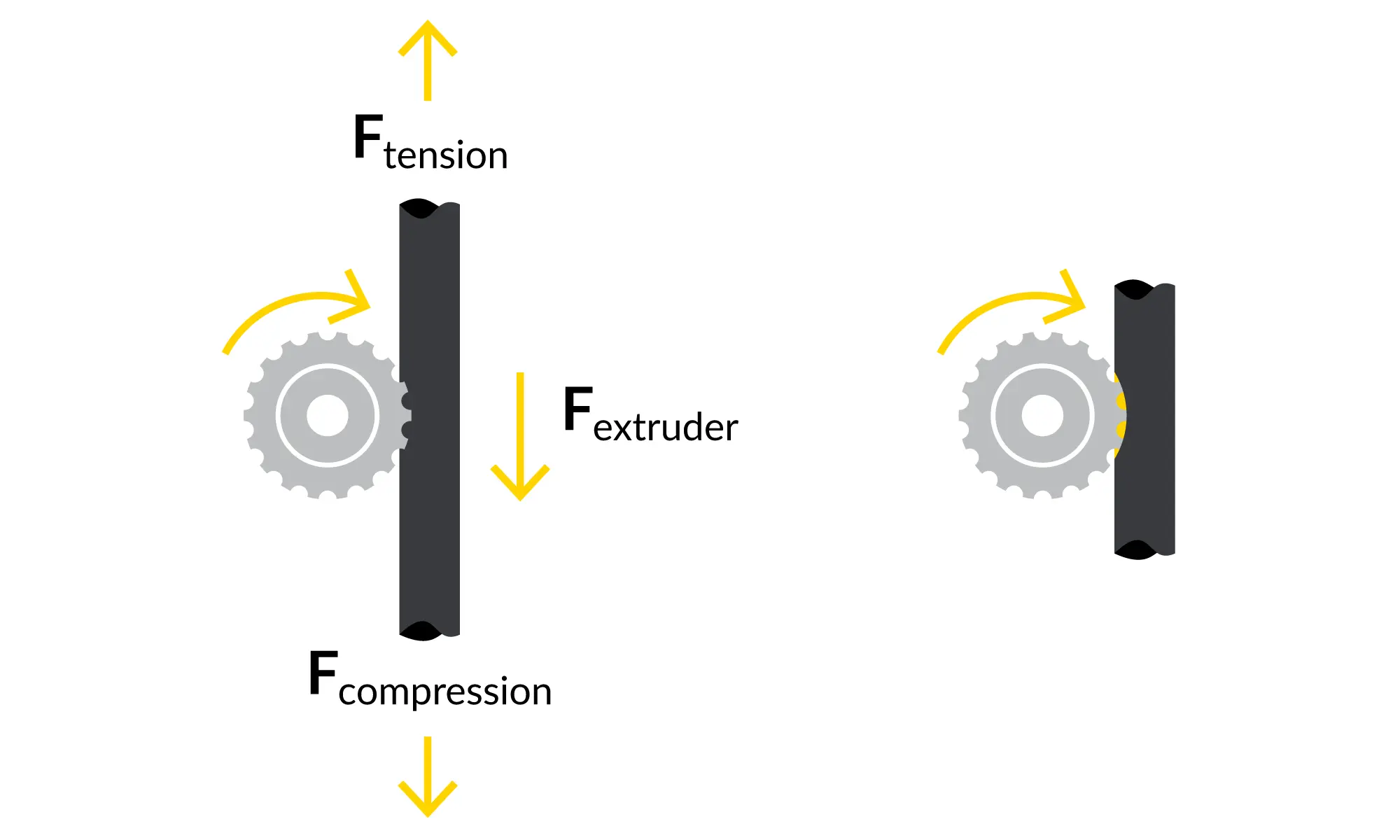
re:3D took an intense look at reports of “filament grinding” submitted by our Gigabot user community, taking input from all the spheres within our company. It turns out that “filament grinding” means different things to different people, so our first step was to agree on a common lexicon and definition. We landed on a concise problem statement: “Customers experience poor extrusion performance due to the extruder gear removing material from the filament, “ which captures multiple causes and failure modes or symptoms. The engineering team evaluated, modeled and tested printer components all along the filament path – beginning at the spindle holding the filament spool down to the exit of the extruder nozzle. While recognizing that every user can encounter unique challenges and edge cases, this exercise ranked potential root causes and recommended optimizations in printer slicing parameters and specific improvements in the extruder manufacturing process. We expect these internal improvements and updated slicer profiles to improve overall reliability and print quality.
During check-ins with our customers, we also receive a lot of interest in “automatic bed leveling” – another phrase that can have multiple meanings. We have incorporated an inductive sensor into the Gigabot’s extruder assembly and integrated the necessary software to allow the sensor to quickly map variations in the print bed surface and compensate the z-axis in real time to maintain a uniform nozzle-to-bed distance. This “bed mesh compensation” approach can yield exceptional first-layer results, even on a warped or non-trammed print bed. Our software team is working with the sensor manufacturer to improve the interface and provide a quality user-experience within the Klipper environment. After we finish mesh compensation development on our R&D and internal production printers, we’ll invite the user community to apply to beta test this new feature.
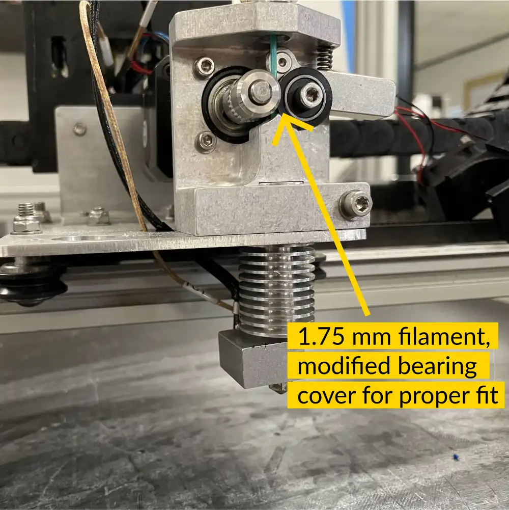
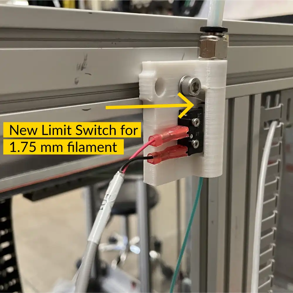
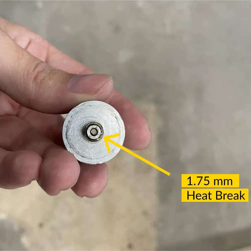
Our user community has also expressed a desire for a 1.75mm diameter filament option for re:3D’s Gigabot printers (where our extruders are designed for 2.85mm diameter filament.) In response, we have designed and are testing a conversion assembly to accommodate the smaller filament. The design has been tested for over 300 hours using a variety of filament materials – including flexible filament. It will soon be released as a kit which can be installed by users in the field.
Specific to re:3D’s FGF platforms, the engineering team has focused on improving the performance and reliability of the extruder assembly. The standard ⅝” compression screw has remained unchanged, but the active feeding mechanism (i.e., the ‘crammer’) is getting a full overhaul. Feedstock with poor flowability such as coarse or lightweight plastic regrind and some TPU/TPE resin pellets can have difficulty flowing from the hopper to the extruder via gravity. The crammer provides an auxiliary auger to force these materials into the extruder body. The new design allows for higher and more uniform throughput, and increases reliability by using a stainless steel auger and machined components. Photos and design details, as well as a link to apply to be a beta-tester, are posted here on our User Forum.
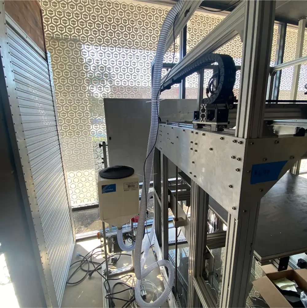
In conjunction with the new crammer design, we have been testing an “autoloading” system to supply feedstock from a floor-mounted hopper rather than our normal top-mounted hopper. This system uses compressed air to drive an eductor which pulls and pushes the feedstock into the printer’s extruder via flexible tubing. A detection unit is mounted at the extruder which detects when the feedstock needs replenishing and triggers the compressed air to transport additional flake or pellets. The autoloader is currently being tested on a TerabotX which will be delivered in one of our Gigalab projects. It can operate as a stand-alone system or interface with the Archimajor control board and Klipper firmware to automatically pause printing if a feedstock delivery error is detected.
Other efforts underway include designing a more robust coupling mechanism between the extruder motor and the extrusion screw, installing a fourth heating zone to better control the nozzle/die temperature, and a deep-dive investigation into part-cooling for the GigabotX.
We are pleased to announce the upcoming release of Klipper Stack v0.5.0. This update represents a significant commitment to enhancing backend operations and ensuring our technology aligns with the latest developments within the Klipper community. Our focus on these upgrades positions us well for the introduction of innovative features in the future.
In pursuit of refining the user experience, we have streamlined the machinery setup process, enabling more rapid and efficient configurations. Enhancements include the introduction of prompt menus for various commands and adjustments to the location and visibility of the emergency stop button to reduce the risk of accidental activation. Furthermore, we have addressed and fixed specific issues such as the omission of certain characters and the disappearance of the virtual keyboard on touch-screen devices after each keystroke, ensuring a smoother and more reliable interaction.
This version also introduces a suite of new features and configuration adjustments. Highlights include the introduction of the ‘exclude objects’ module, which offers the flexibility to remove specific models from multi-model prints directly from the gcode mid-print. The ‘gcode arcs’ module expands movement options beyond the basic G1 move, incorporating G2 and G3 moves for enhanced precision. Furthermore, we have eliminated the homing sequence prior to resuming prints, addressing the issue of potential layer shifts on models.
These enhancements and fixes are part of our ongoing commitment to providing a robust and user-friendly platform, setting a solid foundation for future developments. The update is scheduled to release within a month.
Internally, the engineering team is implementing processes reflecting re:3D’s ethos of being responsive and transparent to our community. Our engineering change and design processes are maturing to better engage internal and external stakeholders from the beginning of problem identification and requirements definition through operational release and ongoing support. These changes will help focus our resources on those efforts which will have the greatest impact on customer success and map the work against product roadmaps which have been developed to guide the engineering team over the next 12-18 months and beyond. And as an open-source hardware company and proponents of open science, we will be increasing our efforts to share as much of our learnings with the additive community as possible. This includes making our material testing protocols more robust and aligned with industry best practices and hosting an international, monthly FGF Users Group virtual meetup open to anyone interested in printing with pellets or flake.
Other activities have included improving the printers’ electrical systems and enclosure design. The team also continues to optimize printer software profiles and investigate additional slicing programs available for filament and pellet printing. Finally, additional variants of re:3D’s Gigalab will be presently fielded for evaluations – demonstrating that it is possible to turn waste plastic into usable parts at the point of need through additive manufacturing.
Look for release schedules and more details on all of these engineering initiatives in the coming months. We’ll be sharing via our mailing list, through blog posts and on the re:3D Community Forum.
Stay tuned, and Happy Printing!
Patrick Ferrell
Senior Engineer

re:3D is proud to announce that we bought our own headquarters space in Austin. We will use the space to scale, grow our ability to experiment with Gigalabs in a large outdoor space, and expand our networks in Texas!
The new facility is located in East Austin, known for being a mecca that actively convenes creatives & organizations committed to social impact. This location also allows re:3D to scale locally with University of Texas and Austin Community College initiatives focused on additive manufacturing, while increasing our global presence.
We’re still working out the details, but welcome your feedback at info@re3d.org as we are committed to ensuring a seamless transition.
Below are some FAQs our team has assembled, and will be updated weekly based on your inputs.
You can witness the final move out logistics live on Wednesday May 29th from 10am-7pm. The Houston team would love to high five any visitors as we share memories and plans for the future! More information is located on our Eventbrite here.
re:3D’s new headquarters is located at 1201 Old Bastrop Highway, Austin Texas 78742 (formally the High Sign Brewery). The building can be accessed just off of the frontage road near the 183 and 71 intersection, so if you are looking for something to do before your next flight from the Austin airport, we would love to see you!
Our current Houston headquarters’ and Austin Office lease end May 31, 2024. For this reason we are trying to batch equipment and inventory moves each week to minimize disruptions to our operations. All headquarter operations will be established in Austin beginning June 1 2024.
re:3D has maintained a presence in parallel with Houston since 2013. We are indebted to the Clear Lake community for supporting our founding but are struggling to scale & maintain insurance for manufacturing operations in a hurricane vulnerable area. As Austin offers more opportunities for recruitment, reduced overhead, and active support from local organizations that support our social mission, we decided to move our operations, while still maintaining a footprint in Houston.
Both Charlotte, who is a Co-PI for our NSF Covergence grant, and Patrick who leads our Army Gigalabs grant as well as two NASA awards will remain in Houston. Where they will be working from is yet to be determined, and we welcome your suggestions!
While some of the Houston crew is moving to Austin (so far- Cheyena, Justin, Will, Mitchell, Jordan, and Annabelle), several teammates will be transitioning to their next adventure and welcome suggestions/introductions on where they should be applying!
Orders are being accepted, however there may be delays in for orders placed in May when we transition from Houston to Austin. For this reason, we recommend stocking up on parts prior to April 30th:)
Tours in Houston and Austin can be arranged by emailing discover@re3d.org.
Email info@re3d.org and we will do our best to transparently reply within 24 hours!
Are you ready for a new 3D printing adventure? Join the team! APPLY NOW