How I 3D Printed RWBY’s Crescent Rose

For a long time, my best friend Mason has been bugging me to watch Rooster Teeth’s animated show RWBY. Don’t get me wrong, I love anime, but I was already watching too many shows, and kept putting it off. Then, one day, re:3D’s cosplay enthusiast Rebecca asked if there was some way we could print the Crescent Rose (the instantly recognizable, 6ft tall scythe from RWBY). I immediately said yes, which made me finally binge-watch volumes 1 and 2 of RWBY on Netflix. Much to Mason’s delight, I loved it! I was super excited to make the scythe, not just because of my inner fangirl, but for the creative challenge of creating a 6 foot tall 3 foot wide scythe!
Rebecca and I debated for many hours about how to go about the design for the scythe. As you all might know, the Crescent Rose has the ability to transform into a more compact gun. We discussed the viability of this option ,and ultimately decided that because of the plastic we would be using and the laws of physics, that we should pursue making the best possible scythe-version of the Crescent Rose, and not worry about it transforming.

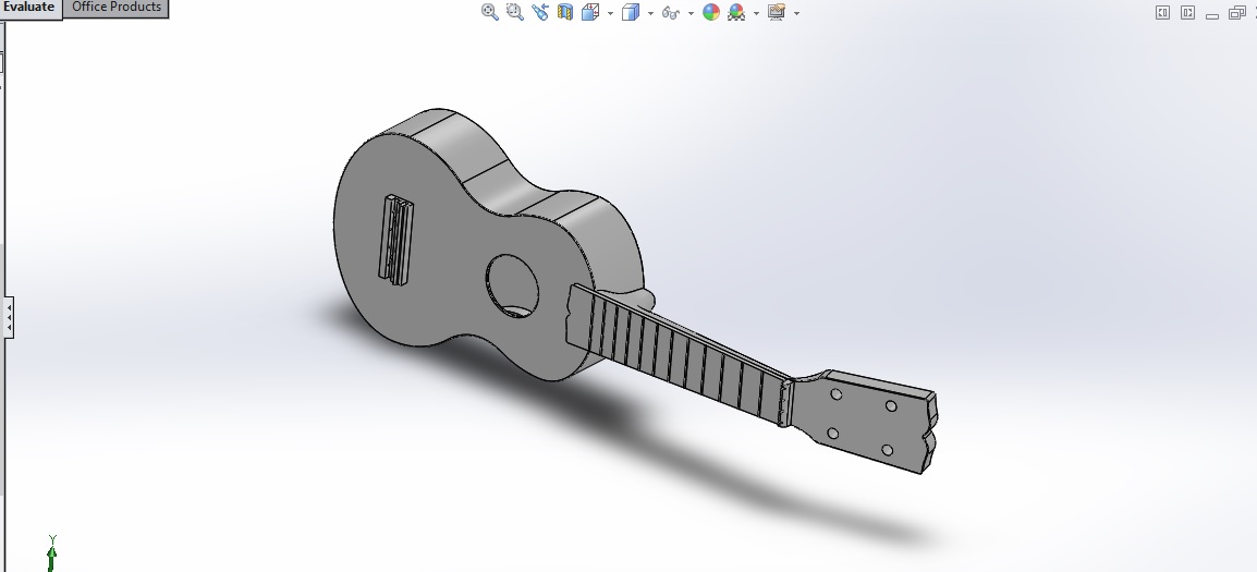
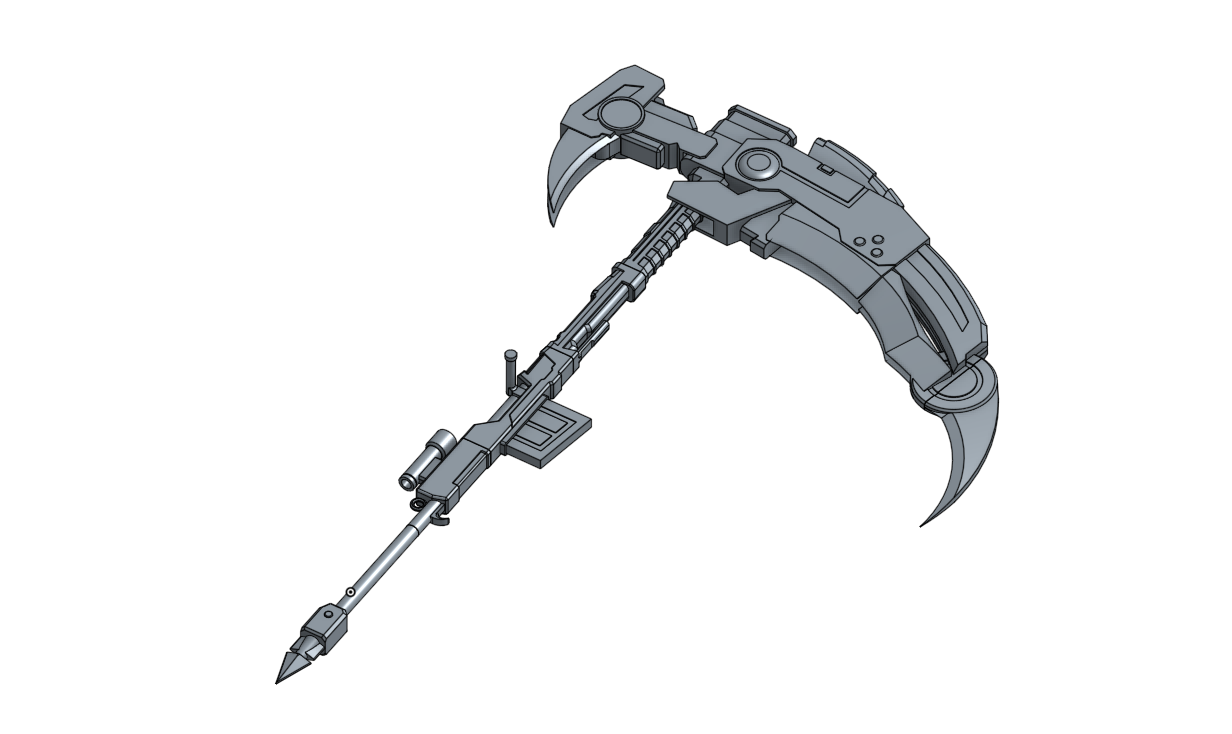
So, I threw myself into research. I spent many hours pausing the show and sketching, as well as staring at various other interpretations of the scythe on google images. I finally decided on a plan of action, and started modeling the scythe in Onshape, a beta CAD software.

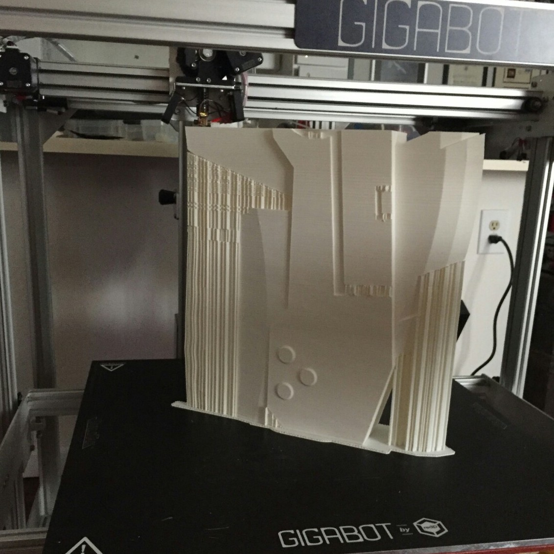
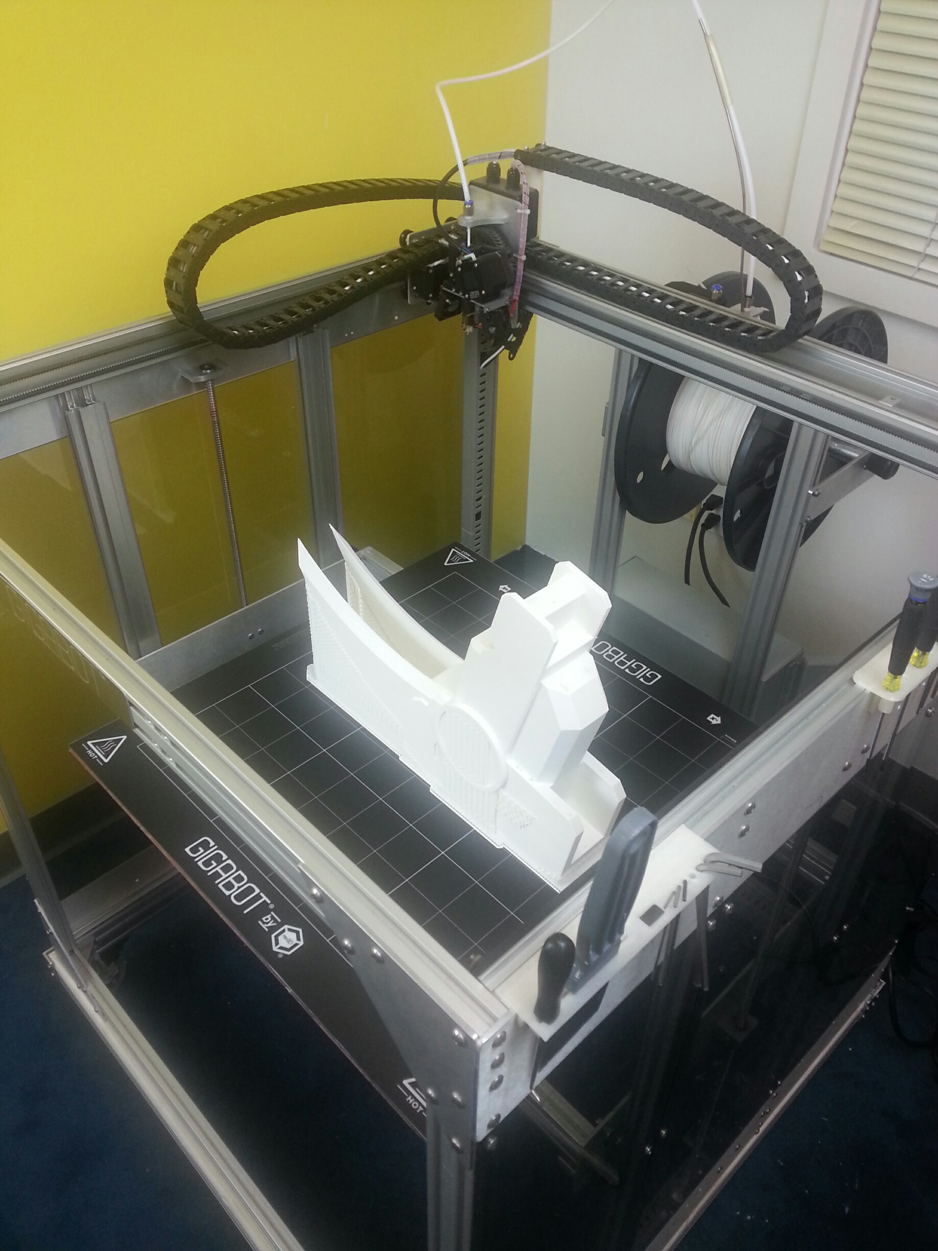
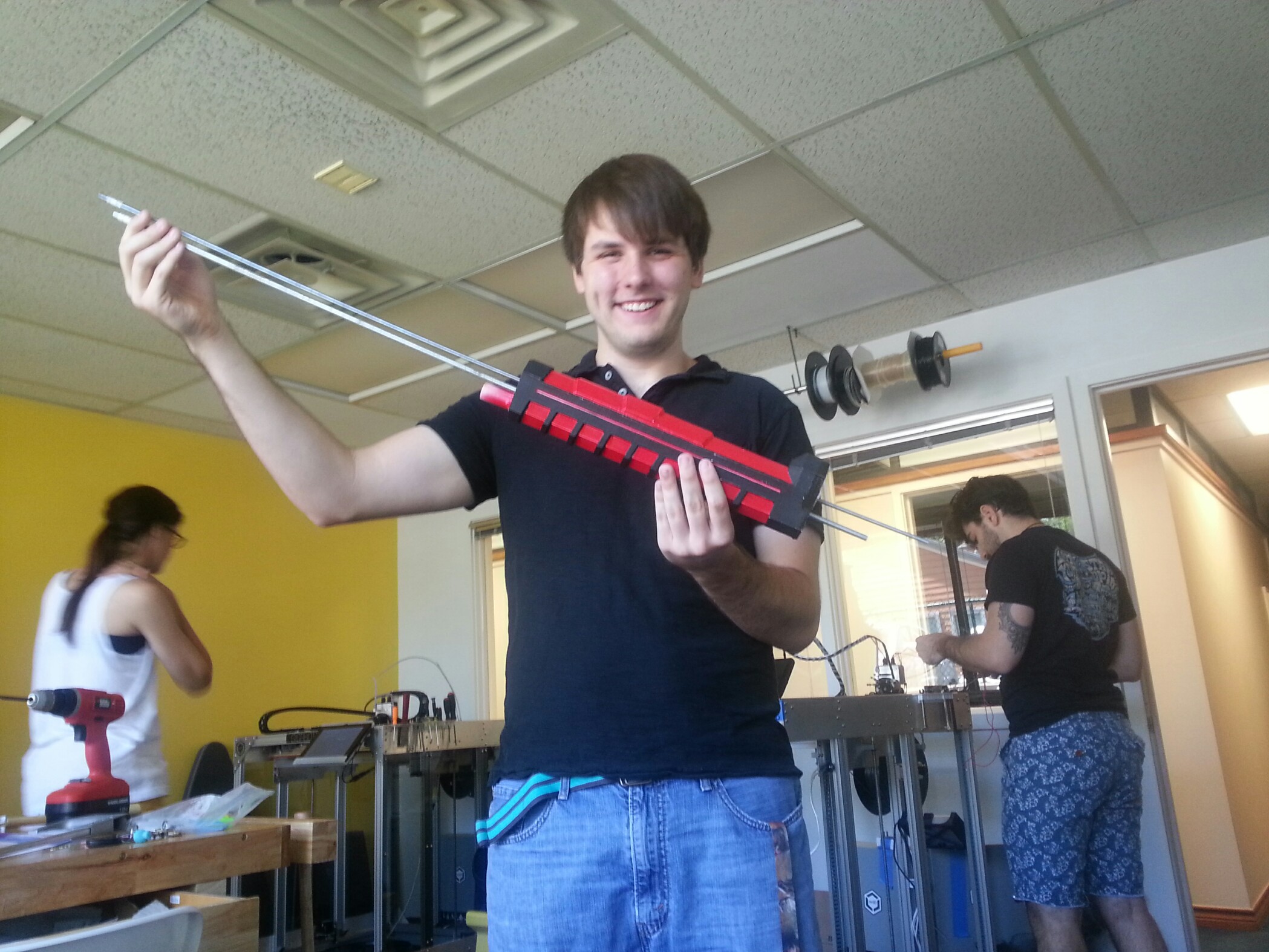
When using a 3d printer, it’s important to keep in mind how your piece is going to be printed. 3D printers start to print from a base layer up, and use supports for overhanging parts. Therefore, I modeled most of the scythe to be easily printed from a flat bottom. Although I could have modeled the piece completely true to the show, I gave up some minor design features so that my prints would be faster and use as little supports as needed. The Gigabot, because of its large print size of 8 cubic feet, allowed me to make the individual pieces much larger and easily create a life sized model of the scythe.

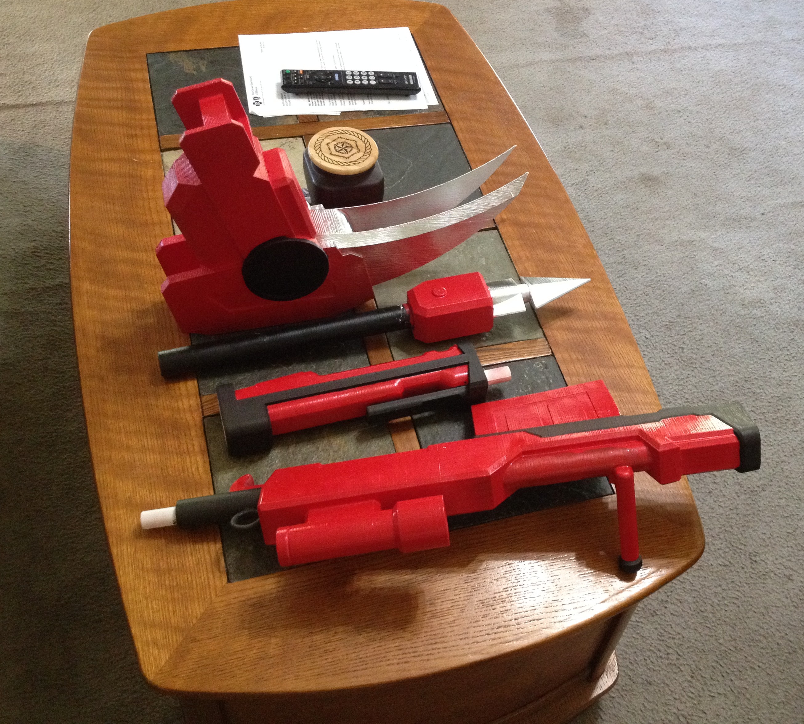
I made the model into 11 different pieces that could be assembled after they were pulled off the printer. I then printed these pieces using PLA on a Gigabot. I used different infills and layers for different pieces, 2-3 layers depending on how much strength I was going to need from that piece and ranged 5-20% infill depending on if I need the piece to be light or not. I usually heat the plastic at around 195-200 degrees Fahrenheit.

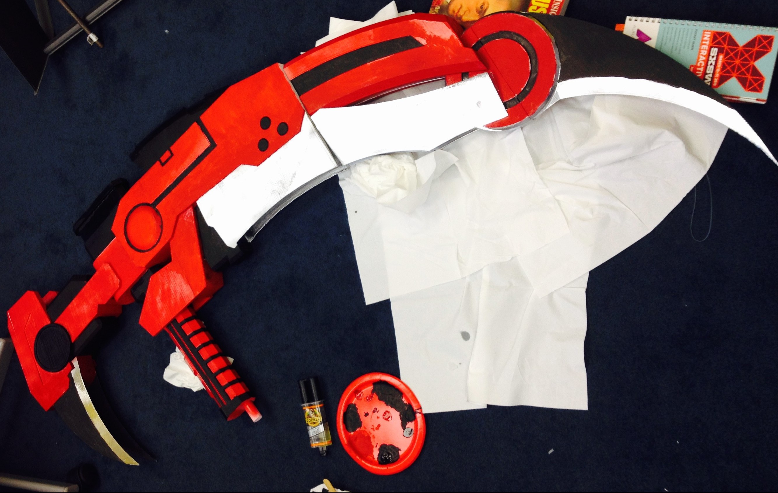
When assembling plastic pieces, together keep in mind in order in which you want to paint your piece, and the different bond strength of the glues or tapes you are using. For the Crescent Rose, I mainly used just basic Gorilla Glue super glue. For more stress intensive pieces, I used Gorilla Glue epoxy and clear caulk to give joints a more uniform look.  

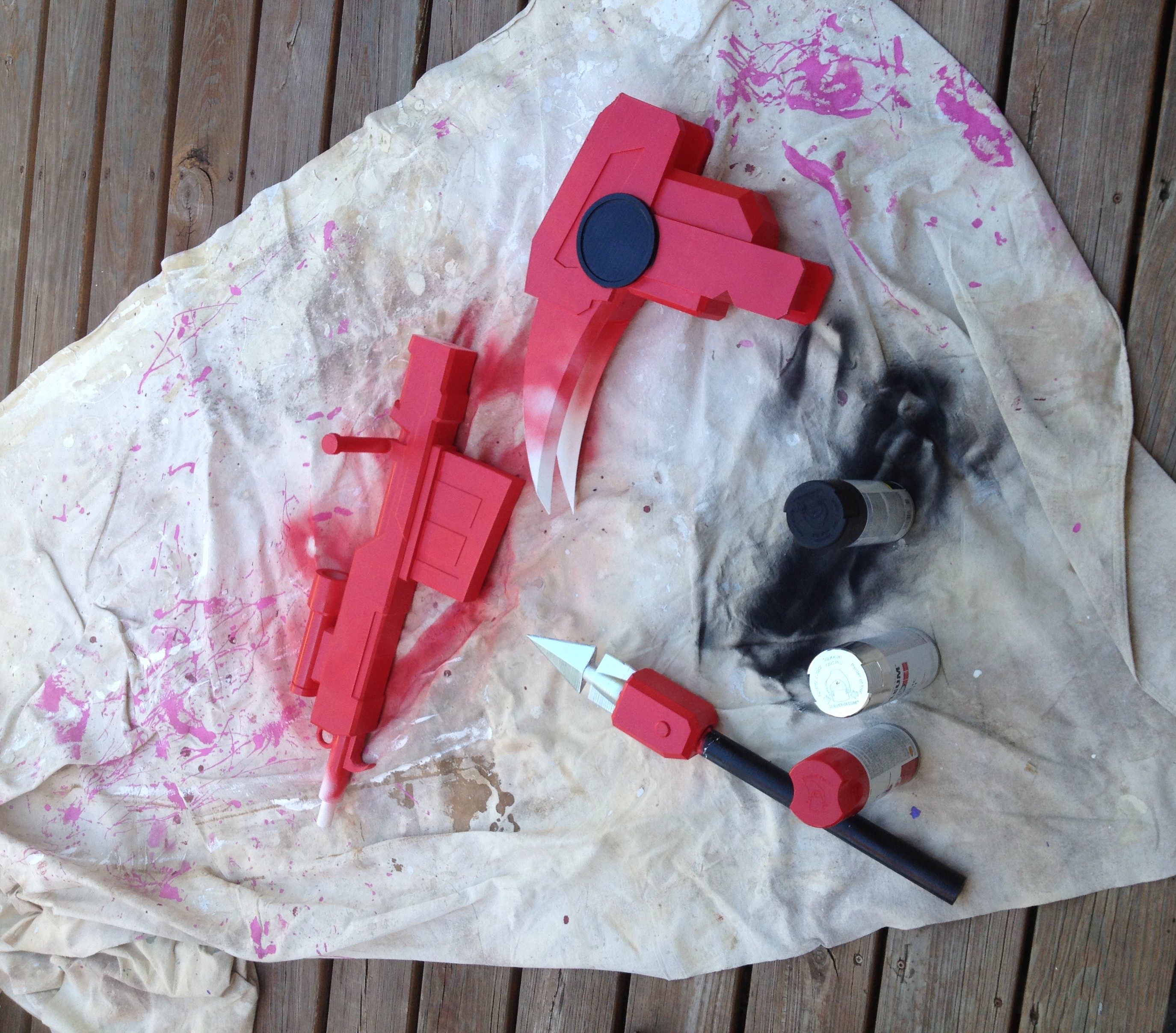
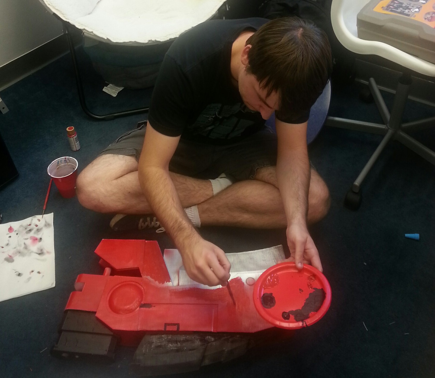
After we had finished printing all the pieces, the next step was to remove all the support material. Then, I sanded down and fixed the smaller print errors such as place where there is a slight over-extrusion on corners or small print-shifts. Finally, I started painting! A timelapse of the process is available below.

I used a basic white primer spray paint that sticks to plastic. This created a good base layer on the models that I could paint other layers of spray paints and acrylic on top of. For the majority of the scythe, I used red and chrome spray paints and then used black and red acrylics and a paint brush to finish detailing.

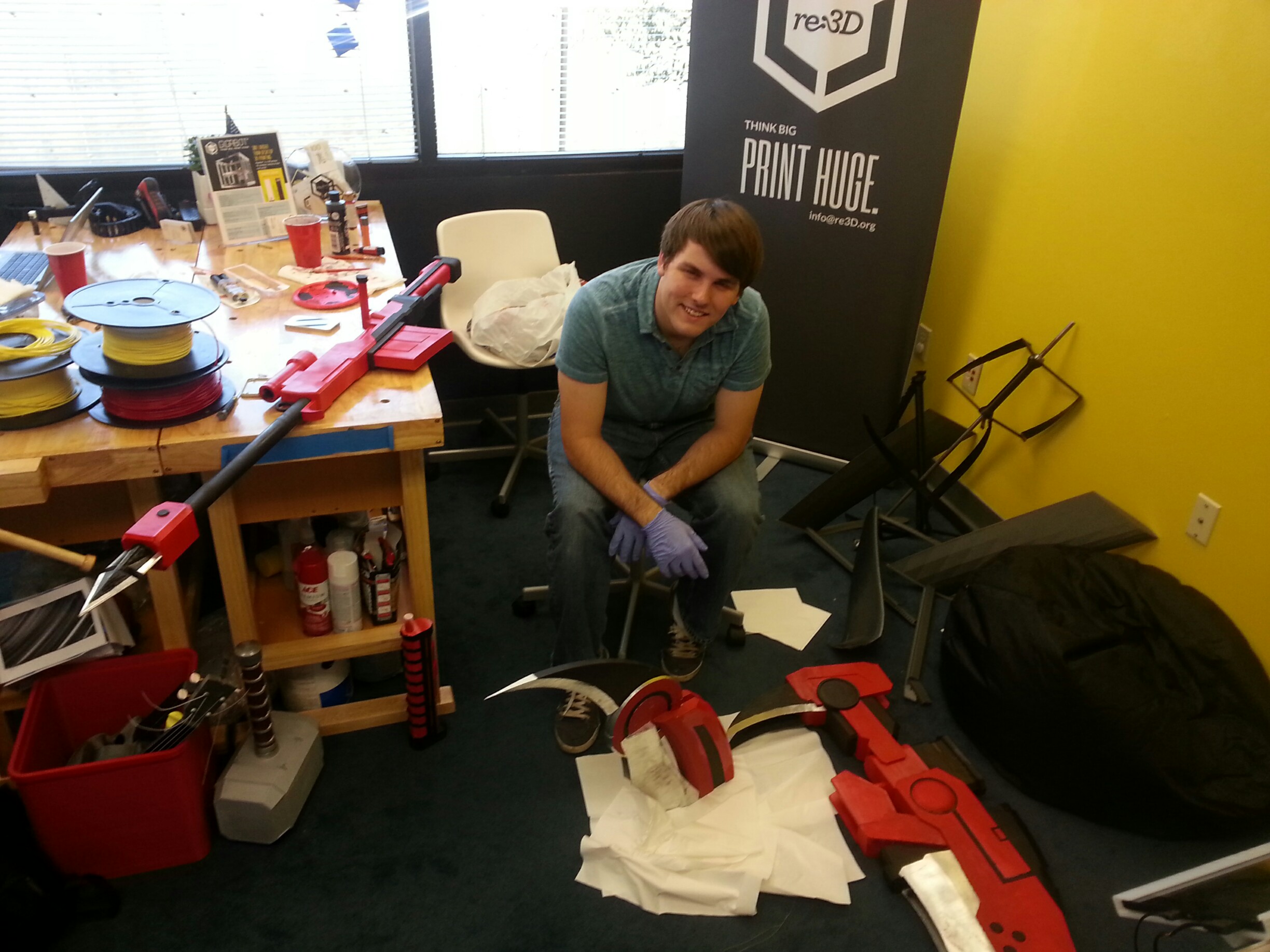
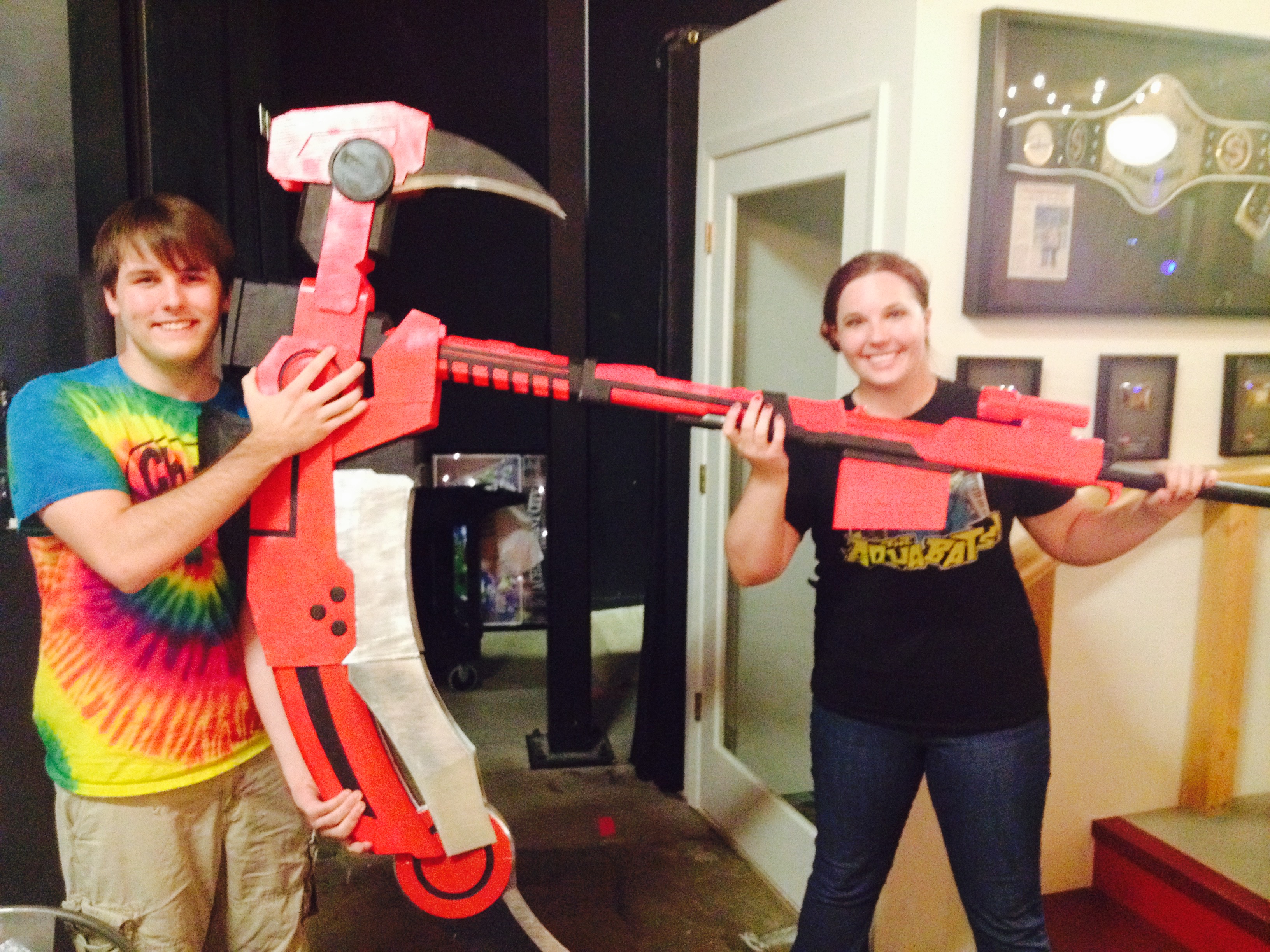
My Crescent Rose actually ended up being a little too big, finishing at 6’10” tall and 4’4” wide. I had the outstanding luck to get to bring my scythe to the Rooster Teeth offices and, who should happen to walk by but the voice of Ruby, the very character who wields the Crescent Rose– Lindsey Jones!

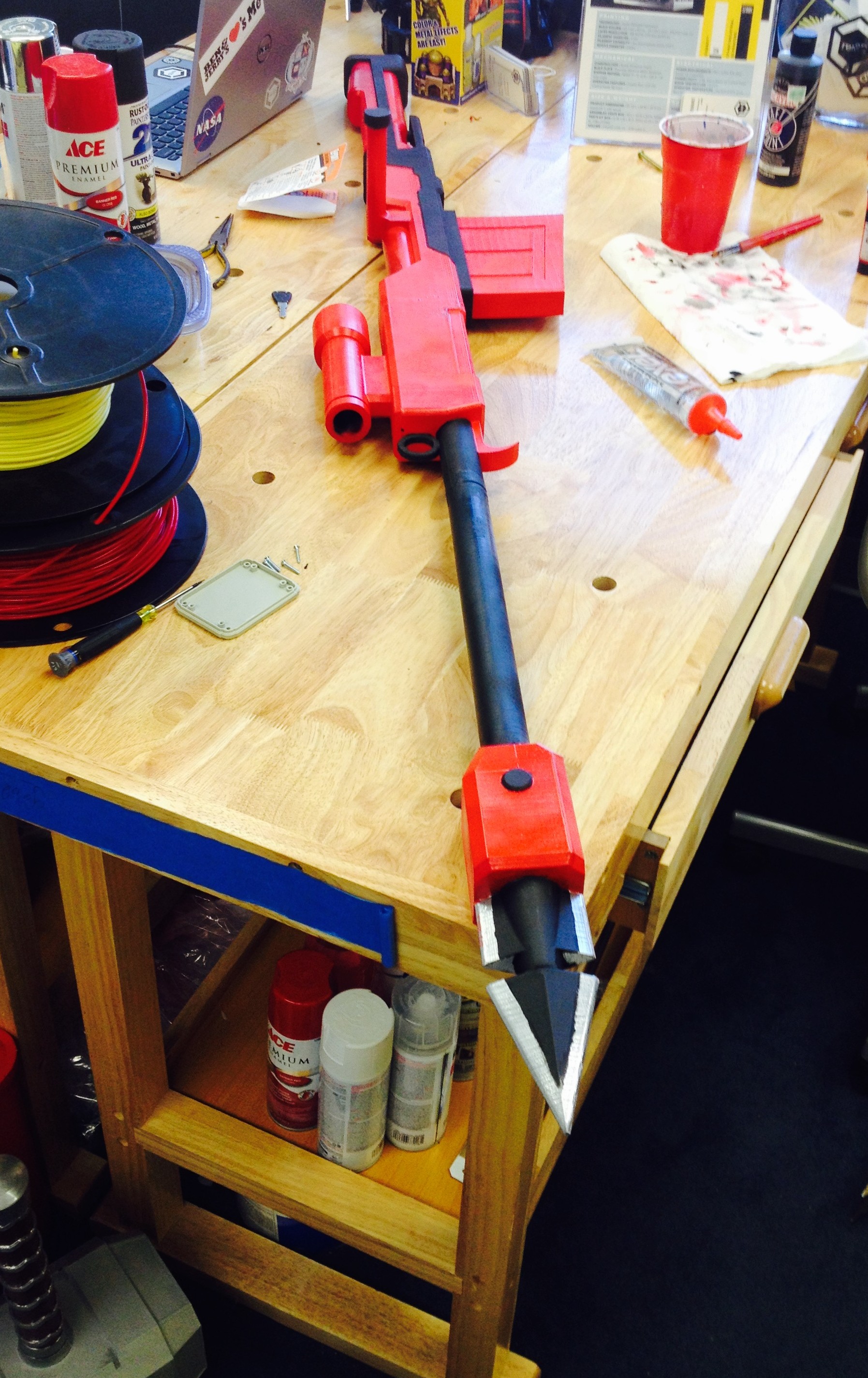
Everything was not all roses and sunshine though. I had some large problems throughout the course of making this scythe. Some pieces ended up being more fragile than I would have wanted, and broke a few times. The overall size and shape of the scythe creates its own unique problem. Even though the material is fairly lightweight, the scythe acts as a natural lever where the fulcrum is where the staff meets the blade, causing a large amount of pressure and tension right at the joint. My solution to this problem was more gorilla glue and wooden and metal rods drilled into the plastic and hammered through to help support the weight.

Another huge problem that occurred during the print of one of the pieces completely failed on us. The head of the Gigabot extruder got clogged 48 hours into the 55 hour print. Fortunately, when a print fails, the print usually has a flat layer at the point of failure. I was able to measure the print, and edit my model accordingly so, so I could print only what was missing. The end result looks just like a filament swap mid-print. I credit the ease of this fix to the great usability of OnShape.

Finally, the last and probably worst problem I ran into was the Texas Summer Sun… This is a problem that is unique to people in the south who use 3D printers. Even though the plastic melts at roughly 200 degrees fahrenheit, your print will warp if left in your car or your backyard too long. This happened on the largest piece of the scythe and caused my really nice print fix to be extremely noticeable. I had to reheat my piece and to try and warp it back to a usable condition– with limited success. I decided at the end that the condition of the piece after I re-warped it was good enough to merit not reprinting 55 hours worth of plastic.

In order to save you some work modeling, I posted the files on Onshape so that you can print RWBY’s Crescent Rose too!

I’m unveiling the files at RTX at the re:3D booth prior to our Panel today (Aug 8th) on 3D printing & cosplay. You can check out the panel at 1pm at the JW Marriott, Room 303.

You can find me on twitter @jacobelehmann to discuss the process in more detail.

Below are the sources I used to help me create my model.

  • http://i.ytimg.com/vi/rST5VxiZ_gE/maxresdefault.jpg
  • http://goo.gl/9XzVMq
  • http://goo.gl/SsO63J
  • https://en.wikipedia.org/wiki/RWBY
  • http://goo.gl/r6x12t

Thanks for reading!

Jacob e lehmann

Blog Post Author

3D Printing Musical Instruments: The Ukulele

Pranathi Peri is developing a set of 3D printed, playable musical instruments for her summer internship. In her own words, she describes her design process:

Have you ever wanted to 3D print your own ukulele? Well now uke can! For the second instrument of my 3D printing internship, I decided to design and print a ukulele. After all, who didn’t trawl the internet looking for the best acoustic guitars under 300, and then end up with a ukele anyway because it was cheaper? They have such a charming aesthetic, and it’s that student living nostalgia that I wanted to try and tap back into. It also dramatically simplifies the process of choosing an acoustic guitar for your child, you can just print one instead now. Although, we have to admit, perhaps it won’t have the same charm.

The history of the good ol’ uke goes way back. During the late 1800s they were first introduced as instruments in Hawaii, where its name literally meant “jumping flea.” Well-known songs like I’m Yours, by Jason Mraz, Riptide, by Vance Joy, and Imagine, by John Lennon have familiar ukulele riffs which have contributed to the popularization of the instrument, yet these bands use the ukulele in maybe one to two of their songs, and then proceed to abandon it.

I know what you’re thinking; why would I want to design such an uncommonly played instrument?

Although the ukulele is not a widely sought-after instrument like the electric guitar, and piano, I decided to design and print it because it combines the aspects of many popular, commercialized instruments. For example, the ukulele is compact, like the violin, but is not as susceptible to external factors that may may warp the acoustics. It retains the same resonance as the acoustic guitar like the Yamaha FGX800c, but within a smaller body. It has strings that can be tuned, just like a piano, but rather than 236 strings, each with their own unique thickness and reverberation, it has 4 which are tuned to C, E, G, and A . For these reasons, and many more, I figured that a ukulele would be relatively easy to design and print, while still containing key aspects of various other basic instruments.

During the process of actually printing the ukulele, I learned many things about designing the instrument itself. One of which being, SAVE YOUR SOLIDWORKS MODELS EVERY 5 MINUTES. There is nothing more traumatic than losing a solidworks file which you had just finished after 1 solid week of work.

However, the portion of this project in which my learning fared most, was the printing, and post-processing of the instrument. Failed prints were rather frequent in the first stages of printing. During our first attempt at printing the body, we decided to orient the body to stand at a 45 degree angle, in order to print it all in one piece. Little did I know that what would be printed would look something like a bird’s nest. Because of some issues with the fan near hot-end of the bot, the print shifted, and proceeded to print midair. Although printing the body in one piece was possible, we decided to go the easier route of printing it in two separate, flat pieces.

Fast-forwarding to when the ukulele was half-assembled, I stumbled upon some valuable learning experiences. In case you didn’t already know this, GORILLA GLUE SUPER GLUE STICKS VERY WELL. Always use gloves when handling super glue. (I may or may not have learned that the hard way.)

The fretboard took several prints, but I had already expected this when I was designing the ukulele. In order to get the placement, and height of the frets just right, it would require some trial and error. This is why I made the neck and frets separate pieces in my model. The first fretboard I printed was way too thick, causing the strings to collide with the higher-up frets. This ended up producing not-so-pleasant vibrations. The fret placement was also a little bit off, causing all the notes to be disturbingly sharp.

The second fretboard was more successful, not only because the black filament made the ukulele look more sassy, but because the fretboard was skinnier, (eliminating the unpleasant vibrations) the frets were taller, (facilitating the playability) and the fret placement was shifted, but wasn’t shifted down quite far enough.

Which leads us to the third fretboard–perfection. That wrapped up project uke once and for all–or so I thought.

My crowning achievement was playing a funky ukuleke riff for the first time. Then I did something very, very, VERY stupid. I left the 100% completed ukulele in the car for no more than 45 minutes, and by the time I came back, the ukulele had completely warped. Because the body of the ukulele was so thin, it had actually folded in on itself, and left the bridge, shattered.

warpeduke1

This didn’t upset me though; I thought of it as a way to make improvements to ukulele 2.0, that I had missed in the original. For example, I could combine the frets and neck, to eliminate the number of parts I had to super-glue together. I also had the chance to make an awesome video for the re:3D What NOT to do 101 When 3D Printing You Tube Channel!

However, after exploring this option, I realized with support material the model is still best split with the fretboard separate so I re-printed it just in time for an interview!

IMG_0082

Over-all, printing this ukulele definitely gave me more insight into the musical world. Not only did it open up a new door of opportunity for gigabot, but it also taught me the process of trial and error, and that things rarely ever work out the first time. Another interesting thing I learned about the acoustics of the instrument, was that the PLA filament body actually had a stronger, and more vibrant resonance, as opposed to the wooden ukulele.

I hope to use this new knowledge to lead me into my next project–an electric guitar!

References:

Pranathi Peri

Blog Post Author

@PranathiPeri

What NOT to do 101: Learning to fail from 3D printing

Let’s be honest. 3D printing is hard. Not just because it builds (pun intended) upon the intersection of science & art. It’s a field that despite growing popularity, is evolving lightning fast.

One Month of Hiccups

For those of us at the affordable spectrum of FFF 3D printers (aka Cartesian hot glue guns), we kluge together whatever resources we have available to force a desired outcome. For me, a 3D printing newbie, this involves an impressive amount of hot glue, filament, 4 letter words, filament, sand paper, more filament, nail clippers and…..even more filament as I try, try and try again to push the limits of human-scale 3D printing.

Over extruding with the bed too close to the hot end

As rather impatient non-engineer who just recently learned the difference between a Crescent and Allen Wrench, 3D printing has been quite a journey. My evenings and weekends are all too often filled with endless Internet searches in order to decipher forum lingo and to deduce how to maximize my chances of print success.

Admittedly I also have the benefit of an amazing team to give guidance and correction. Despite the advantage, I regularly make an incredible amount of mistakes as I try to be independent. I have a profound respect for those more fluent in large-scale 3D printing that model success after success online. However, I’m finding I learn more from the fracasos I inspire at least a couple times a week while currently supervising three Gigabots running 24/7.

"Raffling" off failed prints to friends of re:3D at a July 4th party
"Raffling" off failed prints to friends at a re:3D party

So, in the sprit of transparency, and urging of my Coaching Fellowship Mentor Monica Phillips, I’ve begun to document my failures.  My hope is that perhaps that these confessions help another amateur or, at least give my teammates & other lovers of additive manufacturing some comic relief.

Here’s the first of the series. If you’ll excuse the vertical video and amateur filming, we’ll do our best to post one a week to our What Not To Do YouTube Playlist, and perhaps coerce some other members of our team & community to share their laughs, tears, and lessons learned as we work together to take 3D printing to new dimensions.

~ High Five

Samantha Snabes

Blog Post Author

samantha@re3d.org

@samanthasnabes

How to take your Gigabot Off-the-Grid

One of our values at re:3D is to provide 3D printing technologies to communities around the globe, many of whom don’t have the resources we take for granted.  Access to plastic feedstock, a consistent power infrastructure, and reliable shipping services have always been a requirement to play in the 3D printing space. We want to change that. One of the microsteps in this direction is to find other ways to power our 3D printer, the Gigabot, while still allowing multi-hour (and sometimes multi-day) prints to emerge from our 600mm X 600mm (2ft X 2 ft) build platform.

I started experimenting this past week using a 40W solar panel and a car battery, and had some success printing a small test print. I’ve gotten some questions since then and wanted to explain a little more about my setup, and also find out if there were any other (successful or not) attempts to take YOUR 3D printer off-the-grid.

MY SETUP

Our Gigabot takes 110V or 220V mains power, but then immediately feeds that to a 24V power supply to power the motors, hot end, sensors, USB comm port, and display. The only part that makes use of the mains power is the heated bed (the one that can fry an egg).  Since using PLA as an input material usually eliminates the need for a heated bed, I started there.

Disconnecting the power supply completely, I wired the 12V battery directly to our controller board and internal cooling fan. I later learned that this cooling fan was a great audible indicator of voltage levels – but more on that later.  12V is at the very low end of what our controller board can take in, but the real question was how long could it print for?

THE PHYSICS

I like to equate electricity to water coming out of a hose (like in this great tutorial from SparkFun), so to follow that analogy, I had to figure out if I could hold enough “water pressure” (voltage) to keep the controller alive, a large enough “holding tank” (car battery) to last for the entire print, while using solar panels to add enough “water” (power) to the system during the print.

After testing with a multimeter, I saw that the Gigabot draws about 5A at the most, and less than an Amp when idle (to keep the controller and comms alive), and on average about 3 or 4 Amps while printing (since the heating element cycles to maintain a constant temperature). Judging by the rating on my car battery of 70 Amp-hours, I could count on about 14 hours of power.

I should add that we often exchange Amps and Watts freely when comparing power levels. They are only interchangeable if the volts of the system remain constant (12V or 24V for Gigabot, 120V for USA Mains, etc.), since Power (Watts) = Current (Amps) * Voltage (Volts).

Or per the above analogy: Ability to Remove Mud From Car = Size of Hose * Water Pressure.

THE EXPERIENCE

The solar panel I bought from Fry’s was impressive, but at 40W I know it wouldn’t get to the levels I needed, and I could only afford to experiment with one. Plus, pausing a print when the sun goes behind a cloud just isn’t practical, since it would leave many marks of semi-melted plastic along the way, and the stepper motors would lose their homing location. I knew that the final solution would at least rely on some battery power.

We all know what happens when our car battery is suffering when you try to start it: the lights get dim, you turn off everything electrical, and pray that it turns over and you can get home that night. Instead of a gasoline powered motor and alternator to keep the battery alive, I had a solar panel – and it had to last the entire print. So I had some questions – and like any former space station flight controller, I took lots of data.

THE QUESTIONS

Would 12V be enough to power a system that we have been used to operating at 24V since the very early days? Would my Gigabot’s hotend pull down the stepper motors too far on battery power and affect the success of the print? Could I use all of the available power in the car battery to make a large enough object without any transient errors? Could I turn on and off the solar panel or battery charger during a print without interrupting it?

THE RESULTS

At first things looked (and sounded) gloomy. The first few attempts failed, and it seemed that the battery just didn’t have enough power to drive the hotend, motors, and electronics to keep the voltage levels high enough. Even the fan noise sounded sickly – a lot worse then when I had it set up without the multimeter.

firstpicoffthegrid

The multimeter! That was it!!

I had wired my multimeter in line with the positive line off the battery to read a super accurate space-rated amp-draw during the entire print. I had wanted to measure exactly how much was going in and out of the solar panel, and the battery. The measurement itself was actually resisting the flow of electricity (the equivalent of bending the water hose to hear if water is rushing past the fold in the line). Once I removed the multimeter and tracked only the voltage across the battery terminals, I was able to get over 13 hours of continuous printing time out of my Gigabot – enough to print this 300mm (12-inch) tall vase! Here are the (manually entered) data points for that one:

The solar panels are pretty straightforward, and work very similar to the battery charger I plug into the wall, so for the purposes of my experimentation in the garage, I’m alternating printing on battery power with a charger on/off, solar panel connected/disconnected, at varying voltage levels of the battery. I think I have found the limits, since my prints start failing at just about 11V on the battery now.

Also, ever since I automated my data taking process, I get much more sleep at once, without needing to wake up for data takes with pen and paper (and help from Google Sheets). Check out the new and improved version with a little help from plotly!

An interesting part of this method of gathering data is that you can start to see the cycling of the cartridge heater very clearly as the extra current draw pulls the battery voltage down each time the hotend is full-on. This will be useful in tweaking my PID values no doubt, and could also lead to better methods of insulating the hotend so it doesn’t need to heat up as much, thereby saving valuable amp-hours!

NEXT STEPS

Clearly there is a little more work to do before we have a brownout-proof or solar-ready Gigabot out of the box, but I think these experiments prove it’s within the realm of possibility to create 3D objects anywhere – given a robust enough printer, and a light bulb’s worth of energy and imagination.

Chris Gerty

Blog Post Author