Making a 3D Printed Bicycle Prototype

Last summer, Patrick Fiedler developed a 3D printed bicycle prototype for his summer internship.  In his own words, he describes his design process:

Have you ever wondered how 3D printing, renewable resources, and transportation all fit together? Although there many possible combinations, one instance is the 3D printed bicycle project that I worked on last summer. I had the wonderful opportunity to intern at re:3D in Houston, Texas and got the chance to work on this awesome project with the intention of answering this question: Is it possible to 3D print a working bicycle? I set out to do just that. With the large format possibilities of the Gigabot and wide range of filaments compatible with the Gigabot’s re3D hot end, I had the means to get started answering this question. The following is a brief review of my project that I wanted to share with the 3D printing community.

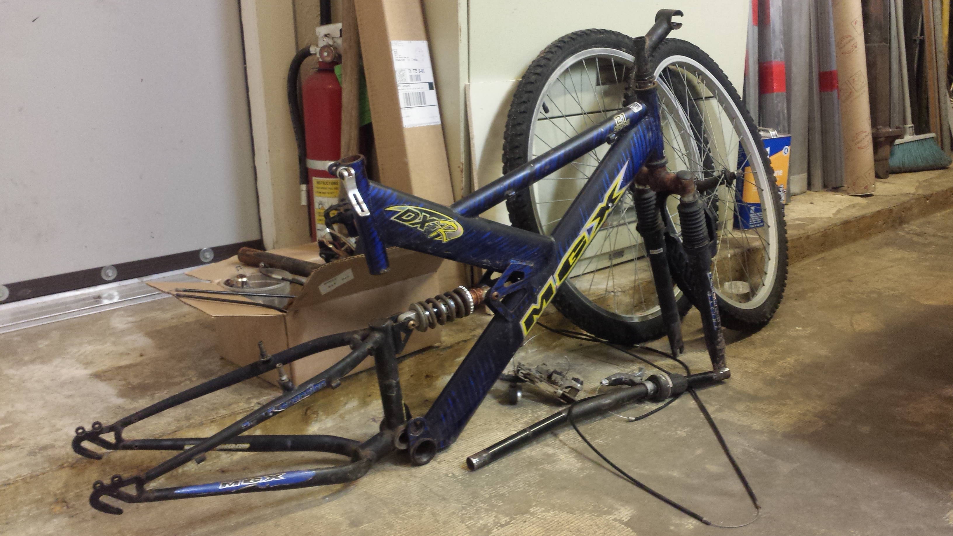
First, I deconstructed a MGX bicycle I found laying around. I analyzed its components and assembly mechanics thoroughly. I had to decide what could possibly be replaced with customized 3D printed components. The most likely option was the frame. With the customizability that comes with any 3D printed piece, I could easily use the modular nature of bicycle parts to attach them to my frame and roll from there (hopefully literally).

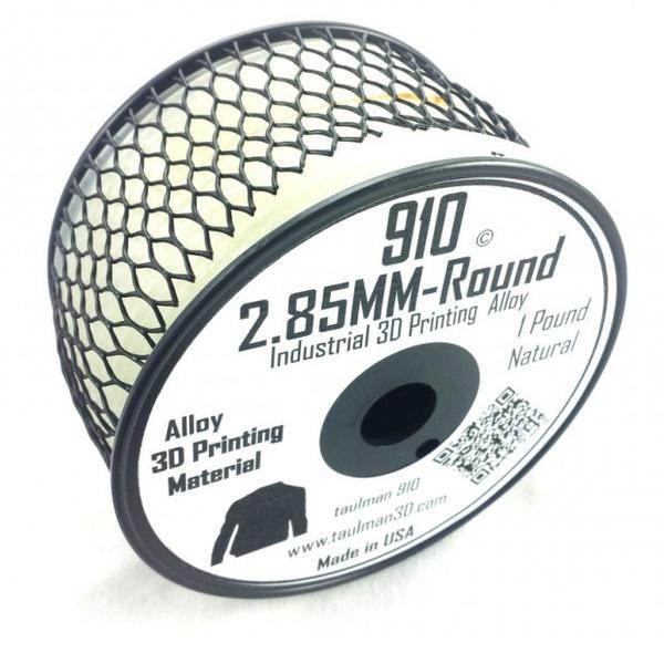
I set out to choose a good filament for frame construction. Thankfully, I had already been making ASTM tensile test samples for research re:3D was doing with Dr. Scott Fish at the University of Texas at Austin. Some of the most common filaments: ABS and PET tend to be brittle so it would not be ideal for a bicycle that experiences many dynamic forces and needs the ductility to flex as well as strength. I settled on Taulman 910 filament which combined the durability/elongation of nylon and the strength of co-polymers.

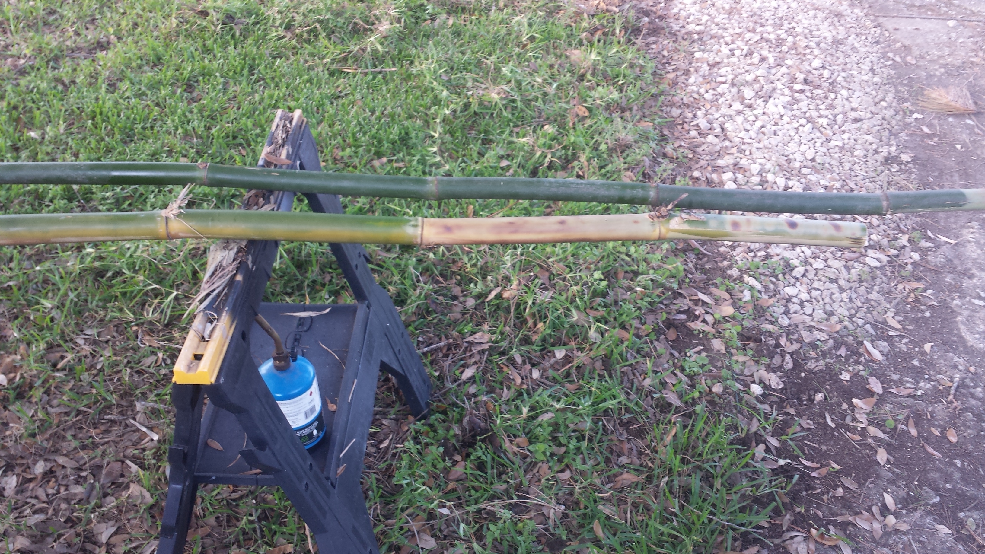
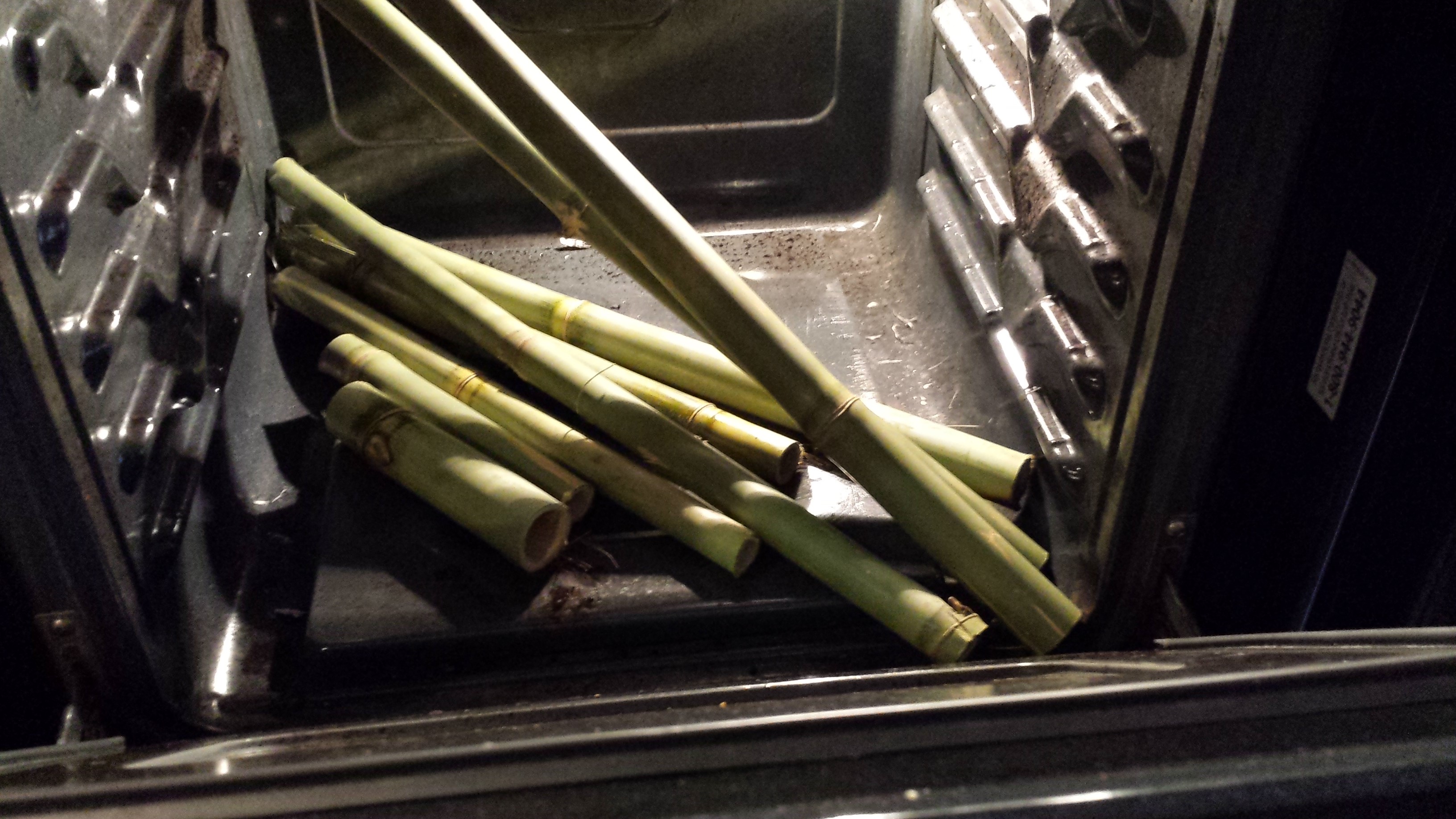
I printed a couple tubes with Taulman’s 645 Nylon filament which seemed pretty strong and had the ability to bend by hand without cracking. However, I realized that a 3D printed tube is much more expensive than metal, and there might be a better material to do the job. I need look no further than outside my bedroom window where a grove of bamboo plants grew flourishing in the humid hot Houston summer. Bamboo grows so fast and is so strong that it would make a perfect renewable tube for the bicycle. I set to work chopping down some plants and then trying various forms of heat treatment from a blow torch, to the oven. A few burnt ends and one smoky kitchen later, I had (somewhat) dry tubes to work with. For those intending to work with bamboo, I suggest either letting them air dry in a dry place out of the sun or at very low temps in an oven with no part of the bamboo touching the oven sides.

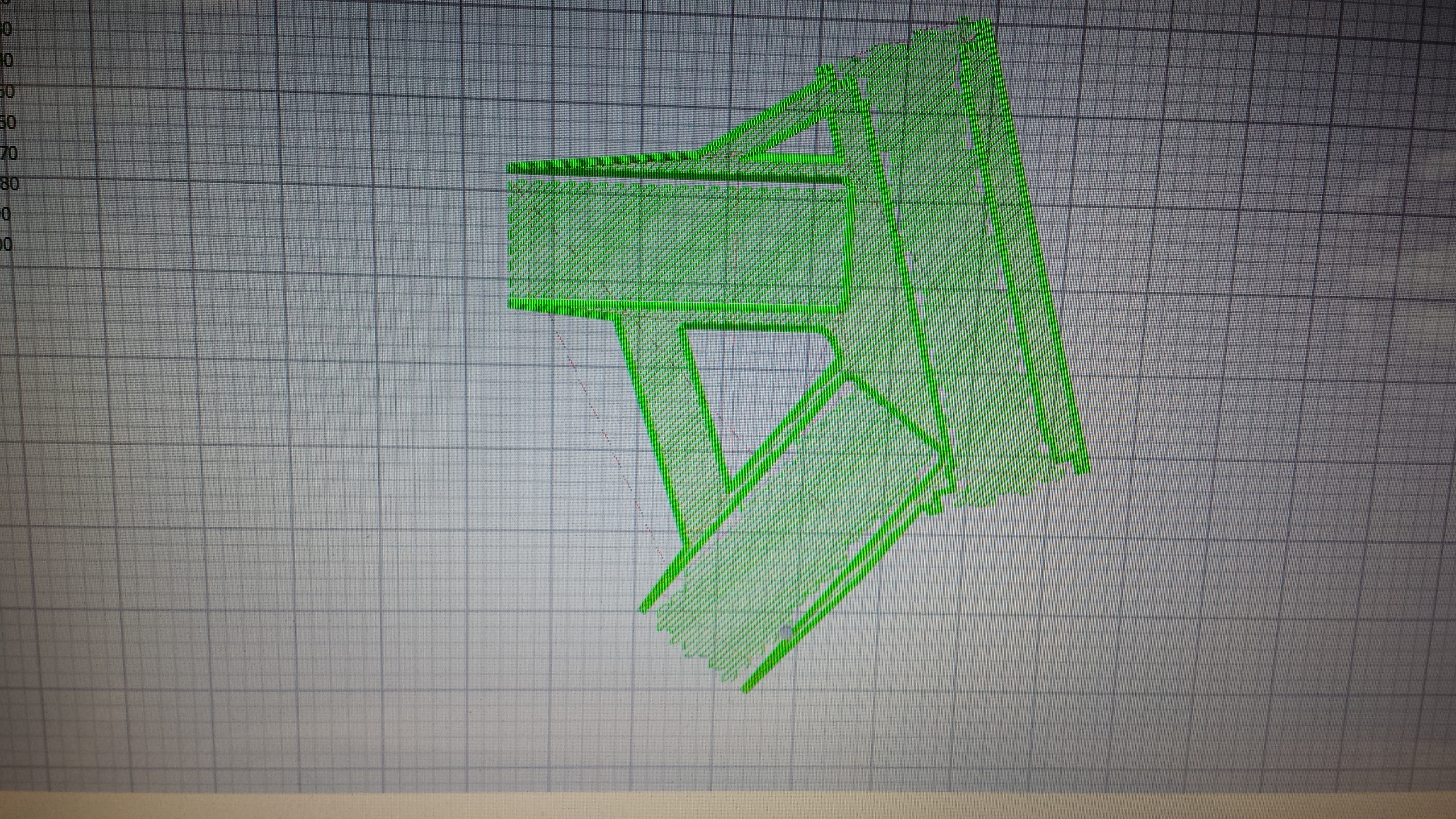
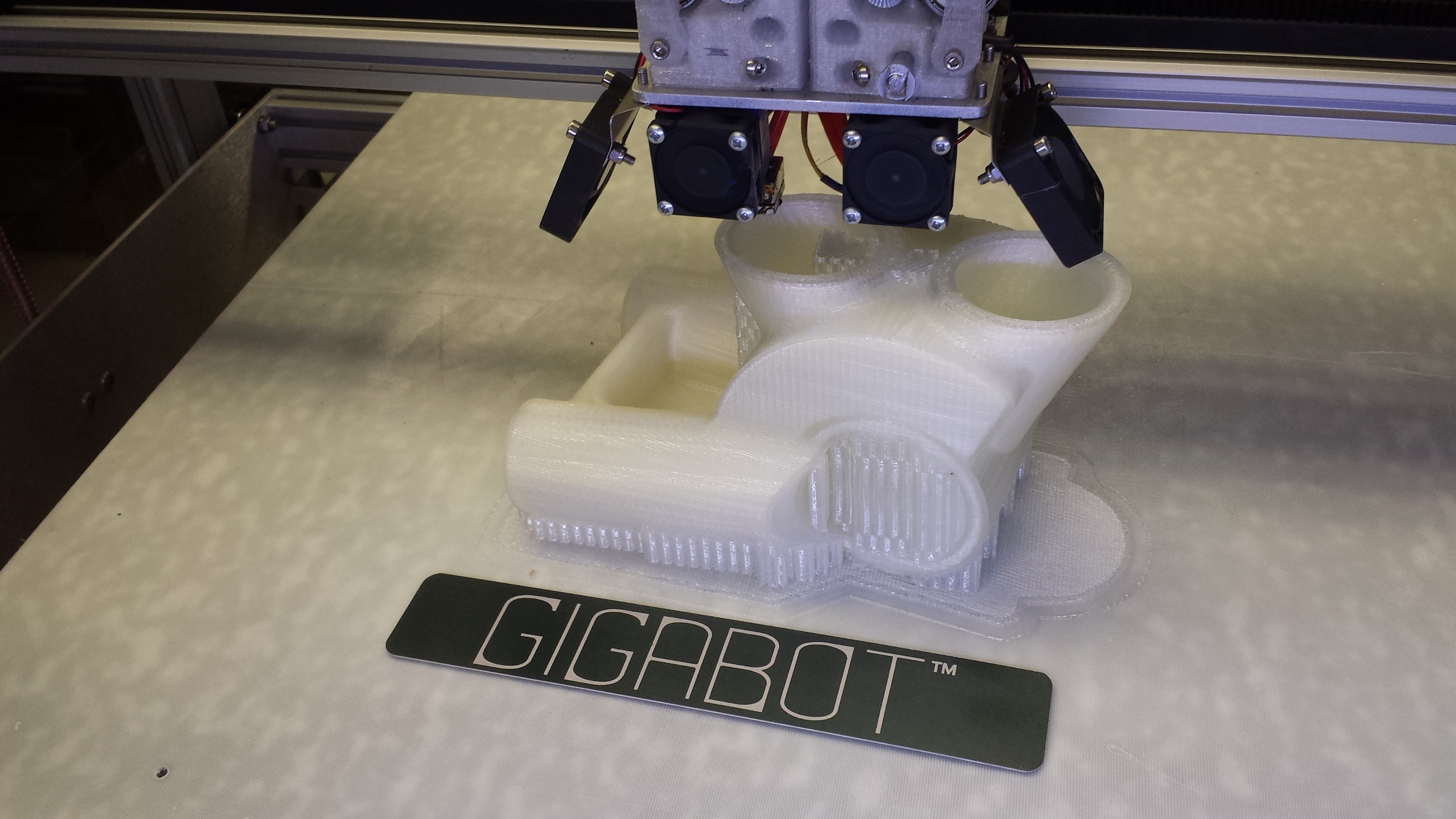
To connect these tubes, I used the Taulman 910 to create modular connector pieces. The pieces were custom printed with receiving holes for the diameter of the bamboo pieces I had cut earlier. The nice thing about 3D printing these parts is that you can conform to the exact geometry of your bicycle dimensions and the tubes you decide on using. Using the Simplify 3D program, I was able to examine my layers to make sure the path of my support structure would work out alright. The connector piece shown here is the bottom bracket where the pedal cranks, down tube, seat tube, and chainstays connect.

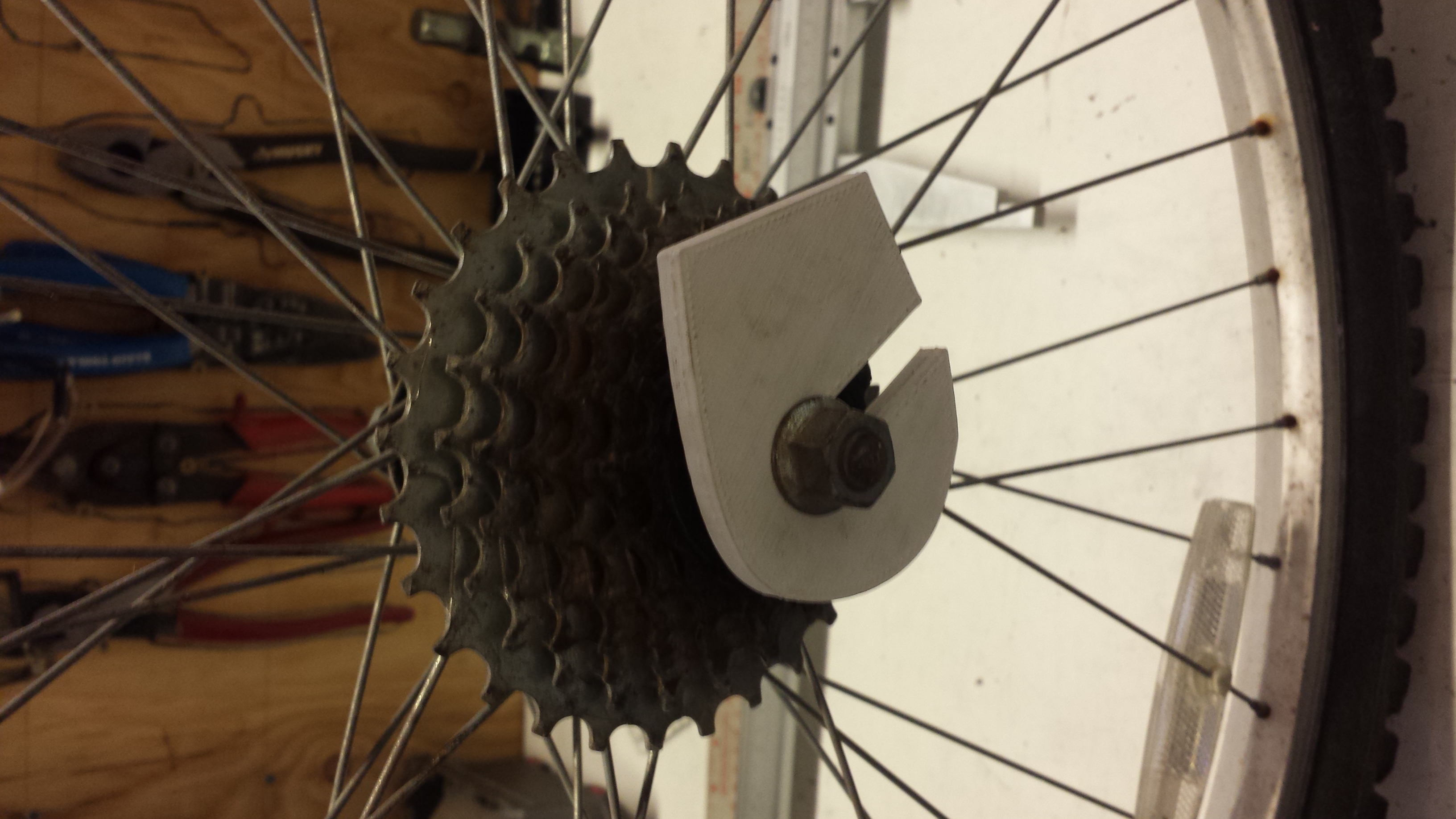
Interfacing with the rest of the components was the next challenge. The bicycle wheels clamped onto fork shaped dropouts which were easy enough to print. The real fun was going to be putting the crank arm bearings and the headset on. I decided to try a press fit approach for the crank bearings. The 910 was ductile enough to press those bearing right in there. Nothing to block rotation. In addition, I found out that you can machine 910 prints. The headset nuts have threads on the internal diameter that needed to thread onto the frame. I threw some of my 3D printed tubes on the lathe, turned them down, and added some threads. It worked much better than expected. Just remember to make your wall thickness large enough so that you don’t machine into the infill.

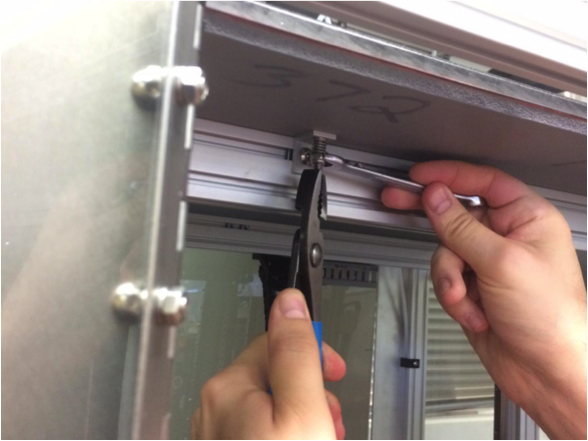
The bamboo tubes, the 3D printed tubes and connector pieces all slid together nicely with only a minor fit problem. I forgot support structure on one of my rear dropouts, thus I heated it in some hot water to make it malleable enough to bend back into the proper shape. Everything was adhered together with a two part epoxy and held in place by my bungee cord fixture.

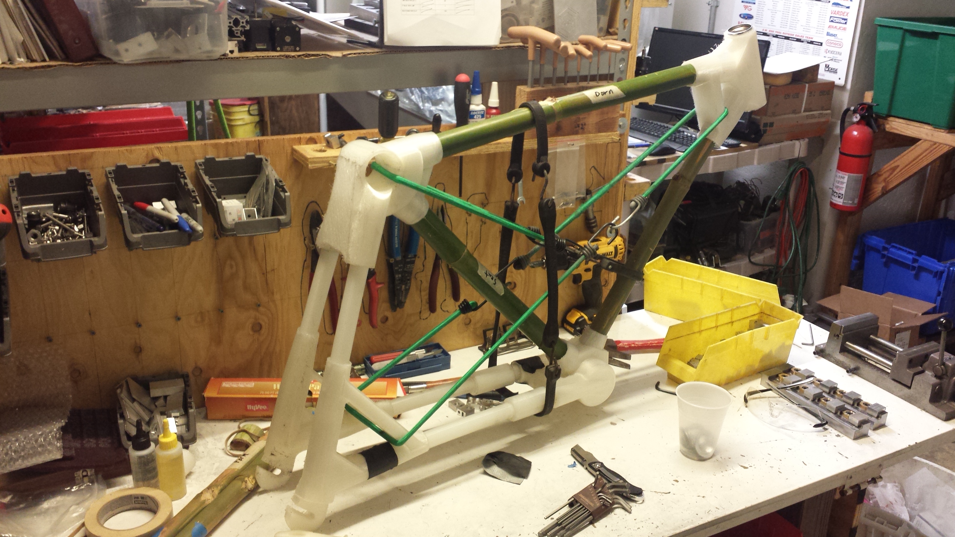
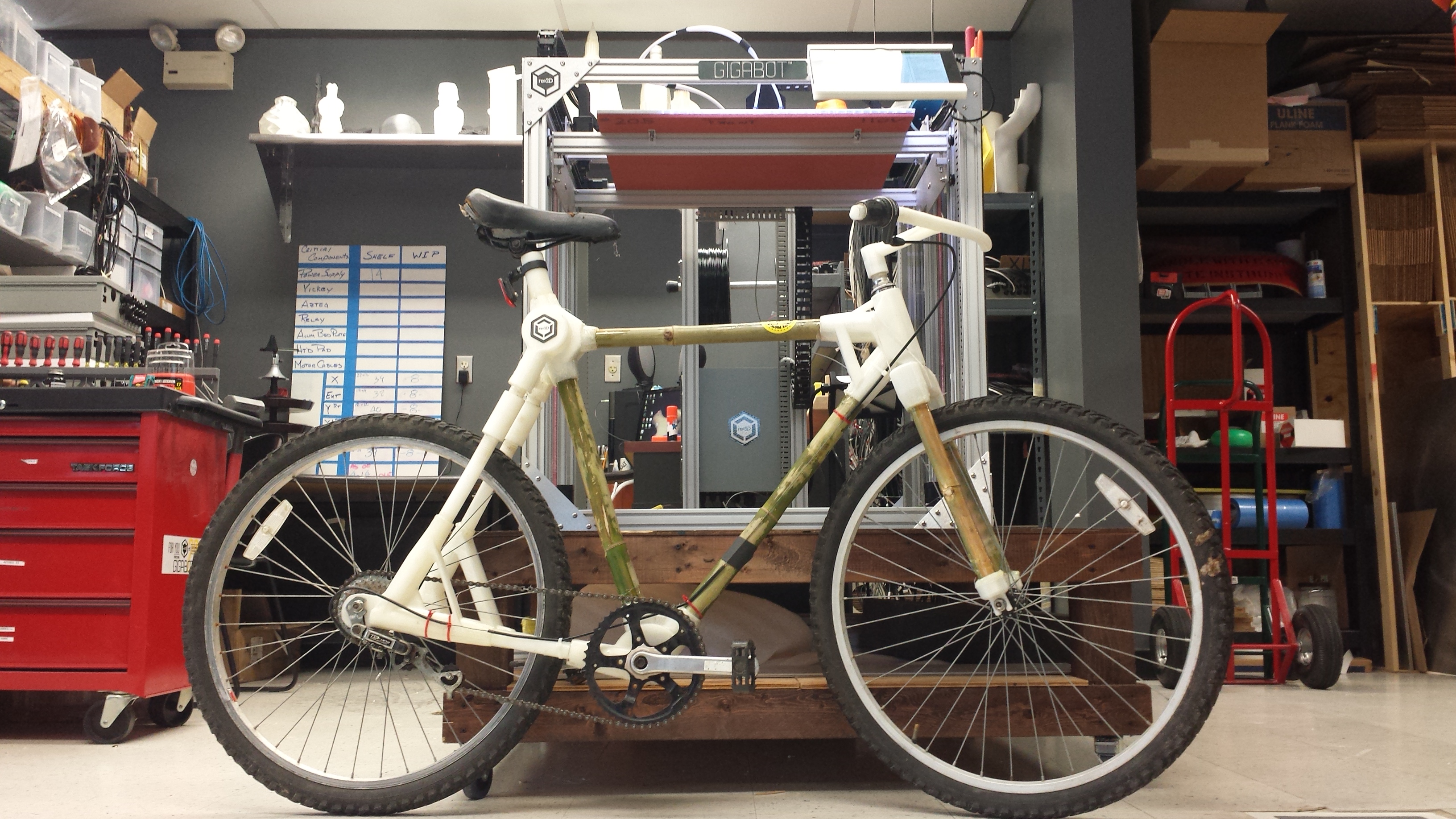
The end product looks much like a real bicycle and may have had the chance to ride like one. A few technical problems kept this prototype from being fully functional. There was some interference along the chain path to prevent usage of some of the gears. Also, the 3D printed tube that runs through the headset above the front fork failed under the large moment that is created by the front fork acting as a lever arm. The rest of the frame, however, was very strong and was able to support weight.

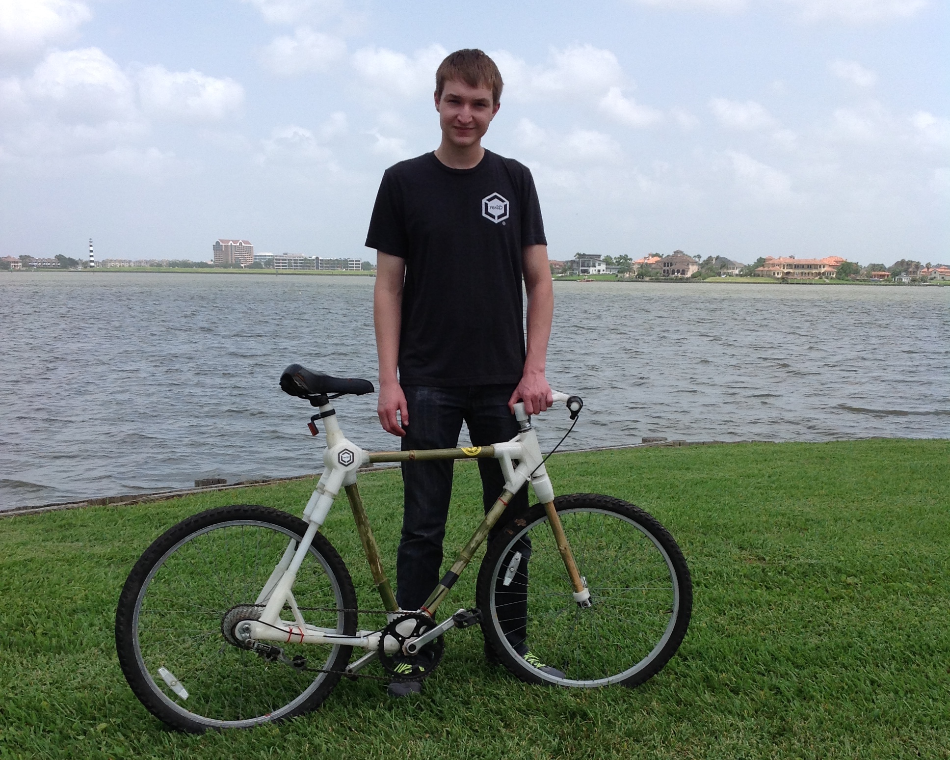
At the end of my time in Houston, I was very surprised at how far the bicycle was able to come along thanks to the structural properties of the Taulman 910 as well as the large format printing capabilities of the Gigabot. If I were to do it again, I would use as much bamboo as possible so it could be renewable. I would also focus on how little plastic material would be needed to make strong connectors, possibly experimenting with more renewable filaments such as PET despite its limitations. Although it wasn’t completely functional, I am confident that yes, it is possible to create a working 3D printed bicycle. One aspect I did like about the modular design was its ability to conform to the exact dimensions needed. All that would be needed would be to change a couple of angles and bamboo tubes lengths, and you would have the geometry for any human rider. You could have a bicycle custom fit to you without needing to settle on a typical configuration. In addition, I liked how easy it was to put together. Anyone with a 3D printer, a bamboo conducive climate, and a nearby bicycle parts repository (like the Austin Yellow Bike Project) Keep your eyes open as I have seen others who are working on their own 3D printed bicycles as well.

All in all, this project was a large amount of fun and made for an amazing summer with the Gigabot 3D printer!

Happy Printing!

Patrick Fiedler

Blog Post Author

Want to continue the research? Apply for an internship at re3d.org/careers!

Solar Pioneers: CoWatt Energy and PowerFunnel

The Lightbulb Moment

When Bill Tolhurst and Cole Brady founded CoWatt Energy in 2013, they shared a passion to become part of the rapidly growing solar power industry, but were looking for a unique opportunity in an already-crowded space. If you have a business then you will probably be looking for some utilities and may need a Utility Bidder, to be more energy efficient. Their big inspiration came from Cole’s background as a 5th generation rancher.

As Bill describes it, there are a lot of innovative things going on in the traditional urban rooftop-mounted space, but almost nothing focused on the unique attributes and needs of rural areas. “Rural customers consume 30% of the total electric power in the US, yet it’s a very underserved market by the solar industry,” he says.

He goes on to explain, “Power is more expensive in rural areas than urban, and usually folks have land. They have the option to put solar on the ground rather than the roof, which is actually the better place for it.” Easier maintenance, no holes or unplanned loads on your roof, and low-risk in the eyes of a firefighter are some of the reasons that ground solar panel installations are more ideal when compared to their roof-mounted counterparts. Many people are starting to buy solar ground mounts to house their panels, if you are unaware as to what these products are, you should check out this guide on the benefits of solar ground mounts.

But ground-mount solar has some long-standing challenges. “We started off doing our deployments the old fashioned way, building everything onsite,” Bill recounts. “It takes a long time and it’s messy – think drilling holes in the ground, cutting steel, and pouring concrete. So rather than being the same guys doing the same thing as everyone else in the space, we started looking for a way that we could be different. “

Bill and Cole began asking themselves the question, how much of the solar deployment process can we move from the field to the factory? Bill uses an analogy to demonstrate the near-absurdity of the way solar is typically done, and how CoWatt is poised to change that.

“Imagine a car manufacturer trying to build your car in your driveway. It doesn’t make sense. The more efficient way is to build the car in a factory and deliver it to you ready to drive. This is the way CoWatt does solar.”

CoWatt’s flagship product, PowerFunnel™, is a factory-assembled and tested ground-mount solar unit that arrives onsite at the customer ready to go. The product is designed so that they nest and stack during transit much like shopping carts, serving the dual purpose of both maximizing space-efficiency during shipping as well as protecting the panels en-route.

“Instead of having to take thousands of individual pieces and put your power system together in the field like a giant erector set, PowerFunnel comes ready to deploy out of the gate.”

PowerFunnel Prototyping

With a solid concept of their product, Bill and Cole started looking for a way to begin the initial prototyping and design of PowerFunnel.

“We were working on a budget, but we also needed something that could produce a fairly sizeable volume.”

With dimensions of four to five feet in certain spots, Bill explained that they chose Gigabot because they can do up to 1/3 scale versions of PowerFunnel, using the same design file they use for the final scale product.

“We used Gigabot to do early iterations, to quickly determine if there were early issues with the design, and to make refinements and improvements along the way. Gigabot allowed us to keep this iterative design process in-house, enabling us to refine and improve our product much quicker than if we had tried to drive it directly into production early.”

Before Gigabot, their prototyping process was much slower and more expensive. They first worked with a third-party company to do full plywood mockups of PowerFunnel.

“The benefit was that they were making us a full-scale prototype, but it was expensive and didn’t allow for rapid design cycles,” says Bill. “We realized we didn’t really need all our prototypes to be full scale, but we did need to be able to take feedback from one iteration and pour it directly into the next to have a continuous improvement loop. Having Gigabot at our office and available immediately rather than going to a service bureau for prototyping meant we could do this very quickly.”

Speed to market was important for CoWatt, and the time savings of using Gigabot made it a no-brainer for them. “It was a weeks-to-days comparison,” explains Bill. “A couple weeks to get a prototype made externally versus a couple days internally.”

But it was the cost side that was even more compelling for them.

“The quotes that we were getting to do a ¼ or even 1/8 scale prototype meant that approach was cost prohibitive if we were going to do multiple iterations,” Bill explains. “The service bureau approach would’ve taken a lot more time and a great deal more money. Gigabot has more than paid for itself just in iterations on the first product.”

And while there are certain aspects of owning a 3D printer that one doesn’t have to deal with when going the third-party route, Bill felt that they were worth it for CoWatt.

“There is a learning curve, but we didn’t find it extraordinary. We didn’t have any prior 3D printing experience. Gigabot uses software tools and components that are well-proven and have a strong support and user community behind them. Overall it was a well-balanced trade-off on just our first product, and now we have the capability to do continuous innovation quickly and inexpensively in-house rather than absorb the lost time and expense of using a service bureau.”

A New Member of the Team

Having Gigabot as what Bill describes as a “captive resource” has proven to be valuable in more ways than just prototyping for CoWatt.

“PowerFunnel is a very visual product: the light bulb goes on when people see it. Being a young company with a brand new product, we needed a way to show it off to people while we were still working on it.”

Rather than relying on PowerPoint presentations and rotating 3D computer models to communicate their product to investors, they used Gigabot to print small, scaled-down versions of PowerFunnel.

“I think that being able to see the product, even scaled down, allowed us to clinch sales and investments,” Bill says. “Gigabot serves the great role of validating ideas quickly and then being able to present them easily to the marketplace and to investors at an early stage when having something tangible can make all the difference in the world of communicating your idea.”

And beyond the investment stage, Gigabot has come into play in yet another new way.

“As we started to go to market, the general public was very intrigued by these small models. We started building 1/16 scale PowerFunnels and using them as handouts for marketing purposes. It gave people a very immediate sense of what the product was about and served as a great physical takeaway.”

Gigabot continues to be an asset as CoWatt, and they see a long-term path for it with the company moving forward.

“This is an industry that moves rapidly, and we’re going to continue to evolve the product to improve performance, so Gigabot has an ongoing role with us,” explains Bill. “Now that we’ve launched the first generation of our product, Gigabot will be a part of the continuous feedback loop.”

A Bright Future

CoWatt announced PowerFunnel in late February, began delivering in late March, and is putting things in place to grow rapidly.

“We have them in everything from ex-urban community acreage homes to hardcore ranching and farming applications,” Bill comments.

“But it’s not only where PowerFunnel is being used, it’s how it’s being used that surprises and delights us.” Bills muses. “Our customers constantly come up with new ways to use our product that we had never imagined.”

One such application not originally on their radar is military.

“The number one cause of injuries and fatalities for our troops in Iraq and Afghanistan is not front line combat, it’s in the transport of water and fuel,” explains Bill. “The ability to generate power without fuel, thereby reducing the risk to our troops – it’s very compelling.”

Since PowerFunnel is a completely integrated solar appliance, one could easily imagine loading 40 units in cargo plane and delivering them to a military outpost, disaster area, or a village in sub-Saharan Africa to start generating power in a couple of hours.

CoWatt is now actively pursuing leads both within the military as well as with international and relief agencies.

More about the PowerFunnel: http://www.powerfunnel.com/

Morgan Hamel

Blog Post Author

DIY Gigahacking: 4 Knob Bed Leveling Kit

The printed parts can be found HERE. Pieces must be printed using ABS except for the knobs which can be PLA or ABS, The arms should use 3 perimeters and 40% infill. The rest of the parts can have 2 perimeters and 30 percent infill.

Let’s walk through the steps to retrofit your Gigabot to use the new knob system. Note: the knobs will be installed in the 4 corners of your Gigabot. The picture shows one centered knob in the back but this is for an early revision of Open GB.

4 Knob Leveling Install

Hardware

  • 1/2 inch-20 bolt (4)
  • 1/2 inch-20 nut (4)
  • Arm (4)
arm
  • Bed Pad (4)
boltcap
  • Bolt Cap (4)
knob
  • Knob (4)
knobagin

Additional Materials used

Building the assembly

  • Put a dab of GO2 glue on the sides of a ½ inch nut
  • Drop the nut into the leveling arm so that the hole lines up with the hole for the nut.
  • Add some more glue into the recess just for good measure.
  • Put some glue under the head of the ½ inch bolt and insert the bolt into the knob so that the head hides in the hex hole; make sure it’s pushed in all the way.
  • Add a little more glue on the other side along the sides of the cutout.
  • Glue the cap on the other end of the bolt.
  • Glue sets in 30 min, cures in 24 hours

Preparing for installation

  • Loosen the bolts holding the bed rails. Lower all bed rails to the bottom of the slotted holes and re-tighten the bolts.
  • Remove the adjustment bolts/springs in all 4 corners.
remove
  • Lower the locknuts on all 4 L-bracket spring assemblies. This will provide the bed with the travel it needs. It’s easier to perform this step before putting on the build surface so that you have access to the head of the bolts.
  • Make sure that the rails are generally level with the bottom motors. The one that I installed these on was a decent amount off.
  • IMPORTANT: Adjust the Z height so that the natural state of the bed is about ½ cm or a little less than ¼ inch from the nozzle. Apply another nut to the underside of the Z limit switch bolt as this adjustment will no longer be used and should remain in place.

Installing the leveling assemblies

affixed
  • Insert 4 magic t-nuts (or regular t-nuts if you’re building it from scratch) along the top recess of the front bed rail. Make sure the nuts are inserted in between the L bracket/springs. Note: The locknut needs to be lower than the one in the image; ignore that.
  • Insert 2 t-nuts into each corner of the top recess of the back bed rail. Make sure they go into the side that is front facing. All leveling arms point towards the front of the machine.
  • Use M5 x 10 screws to bolt the arm assemblies into the t-nuts in the top rail.
  • Push the left arm snug against the left L-bracket and the Right snug against the right L bracket. The back arm will sit just left of the cable tray. Give it about a half inch clearance on the right.
  • Put a line of silicone on the flat side of each of the 3 bed pads.
  • Lower all knobs so that the nubs are almost touching the top of the arms, manually lift the bed and slip the bed pads over the nubs trying not to make a mess with the silicone in the process.
  • Raise the knobs and straighten out the pads. The pads should self-align to the nubs but just make sure the pads look visually straight to the edge of the bed and the rail.
  • Put a bead of silicone around each pad and then removed any excess by smearing it with my finger.

Leveling the bed

mikedone
  • Position the nozzle above the left knob and turn clockwise to raise the bed in that corner. Raise so that it’s almost touching. Do the same for the right side.
  • Raise the back knob so that the nozzle is almost touching the bed.
  • Go back to the front left and use a sheet of paper to keep between the bed and the nozzle. Turn the knob clockwise until you can feel slight friction on the paper. Do the same for the right side, and then do the same in the back 2 knobs.
  • Move the nozzle around the bed and try the paper trick to make sure all is flat. If it sticks anywhere, recheck your 4 points.

COMPLETE!!!

Happy Printing!

Mike Battaglia

Blog Post Author

@mikebattaglia

Made in America: 3D Printing Prototypes for Stump Armour Molds

Meet Travis: A Texan, father, entrepreneur, warrior, and inventor.

re:3D first met Travis in Austin last winter as he was prototyping his second version of Stump Armour: an affordable, accessible device he pioneered in order to expand mobility options for bilateral amputees.

As a combat-wounded Marine, Travis is uniquely qualified to inspire solutions to increase maneuverability for other double amputees while reducing back strain that traditional prosthetics can create. By using himself as the test subject and leveraging business insights he acquired in the 100 Entrepreneurs Project and the Entrepreneurial Bootcamp for Veterans (EBV), Travis launched Stump Armour on indiegogo this week.

stumparmourdurty
Stump Armour Mod 1

About Stump Armour

Stump Armour is a round design that connects to traditional sockets to allow for constant surface contact from any angle. Pressure can be directly applied to a terrain without changing position, allowing amputees to roll themselves up independently when preforming activities close to the ground.  Since the round shape can grab from nearly any position, it works great on uneven/irregular surfaces, so the amputee doesn’t need to focus as much concentration on limb placement when compared to other devices.  Travis doesn’t feel Stump Armour is intended to replace full leg or knee prosthetics. Rather, it’s meant to increase functionality with specific tasks.

IMG_1546

Keeping Costs Low

A key tenant of the Stump Armor’s mission is to make devices as affordable as possible worldwide. For this reason, Travis contracted Mike Battaglia & I last January to see if we could 3D print his vision for a Stump Armour’s Modification. Using Simplify3D we were able to generate a raft & support that could easily break off. The completed PLA prototypes printed great and we were excited to give them to Travis, who planned to use the prints to create a mold to scale Stump Armor globally.

IMG_1549
3D printed Stump Armour Mods 3 (left) and Mod 4 (right) cast at SureCast

Prints in hand, Travis partnered with local foundries who guided him through the process of making his own custom mold to cast multiple sets of Stump Armour.  This week we interviewed Travis to learn more about the process he used to create a mold from a print by working with Stevens Art. Below are the steps that he described:

stumparmourmold
  • From a 3d printed prototype made on Gigabot, a silicone rubber mold was created.
  • The print was covered in an releasing agent that was then covered in silicone, leaving an inlet for wax to be poured in later.
  • After the silicone cured, a 2 piece plaster shell was made.
  • Once completed, the silicone was carefully cut with a razor along where the plaster shells come together so it would come apart into 2 pieces.
stumparmourpour
  • The shells were clamped together and hot wax was then poured into the inlet.
  • When the wax hardened, the wax casting of the original print was removed.
stumparmourwaxdone
  • The wax cast was then dipped in a a ceramic slurry and power coat until a hard shell formed.
  • This shell was fired in an oven to harden the cast melt the wax out.
  • Metal was poured in and the ceramic shell was broken off after it cooled.
  • A metal replica of the original 3d print was then ready for finishing!
stumparmourstacked
Stump Armour Mod 2

Using lost wax casting, Travis was able to do his first production run of Stump Armour, which is now available to other amputees on the Stump Armour indiegogo campaign. You can support Stump Armour’s next production run and Stump Armour donations at: https://www.indiegogo.com/projects/stump-armour#/  until July 1st.

stumparmournewlogo
Want to learn more?
  • Email: info@stumparmour.com
  • Web: http://www.stumparmour.com/
  • YouTube: https://www.youtube.com/channel/UCsObkfi6W6x2B6dpZ89_CGg/videos?sort=dd&view=0&shelf_id=0
  • Facebook: https://www.facebook.com/Greens-Machines-LLC-716439551739895/
  • Google: https://plus.google.com/u/2/b/106145756742784523319/106145756742784523319/posts
  • LinkedIn: https://www.linkedin.com/company/10602419trk=tyah&trkInfo=clickedVertical%3Acompany%2CclickedEntityId%3A10602419%2Cidx%3A2-1-2%2CtarId%3A1464716547152%2Ctas%3Agreens%20machines

Samantha snabes

Blog Post Author