April Puzzler Solution Revealed!

Below is the solution to the Monthly Puzzler Chief Hacker presented in our April Newsletter. Want to play? You can sign up to receive our monthly publication by submitting your email address in the sign up at the bottom of re:3D.org. Proposed answers are presented on our forum at: https://re3d.zendesk.com/hc/en-us/community/posts/206262336-April-Puzzler

The Question

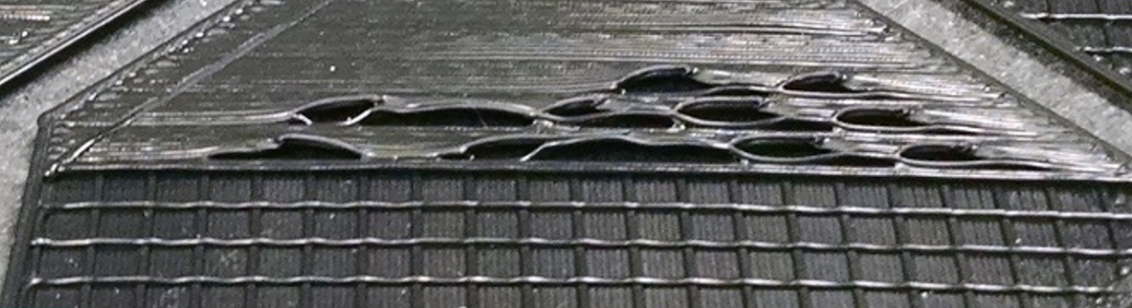
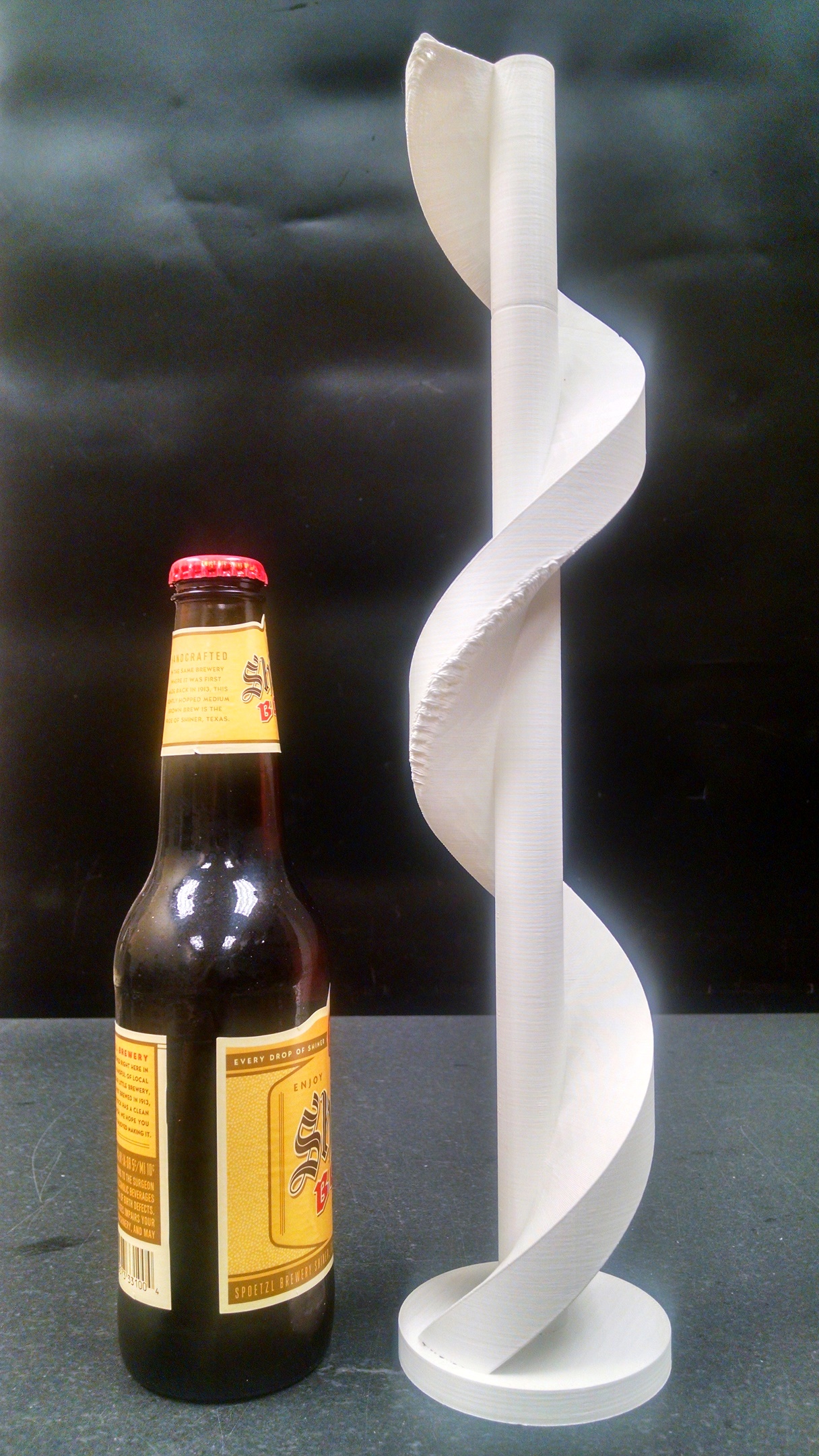
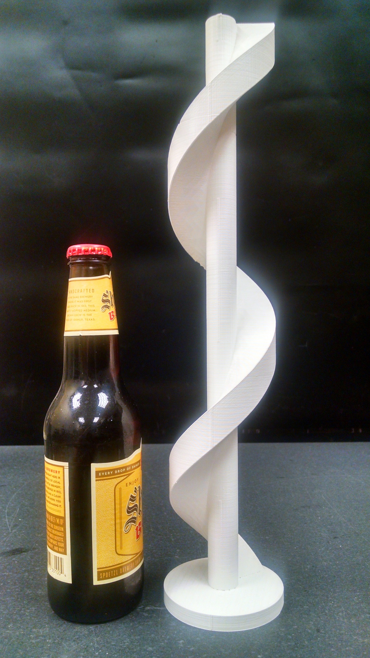
The April puzzler is another print quality mystery. Take a look at the below pictures of an oversized auger screw originally designed for an automated pet feeder. On one side of the auger there is a blemish in the print yet from another view the print shows an excellent surface finish. What is causing the poor print quality on one spot only?

The Solution

The winning answer was presented by whosawhatsis who stated both reasons for the problem.

  1. Uneven cooling
  2. Steep overhang with no support

Great job to everyone and keep an eye out for an improved 360 degree cooling feature for the GB3 hot end to give even better printing capabilities!

Happy Printing!

Matthew Fiedler

Blog Post Author

February Puzzler Solution Revealed!

Below is the solution to the Monthly Puzzler Chief Hacker presented in our February Newsletter. Want to play? You can sign up to receive our monthly publication by submitting your email address in the sign up at the bottom of re:3D.org. Proposed answers are presented on our forum at: https://re3d.zendesk.com/hc/en-us/community/posts/205859796-February-Puzzler

THE SOLUTION

Here are the two reasons you will see a visible mark between processes.

Answer #1. If the SECOND process settings (upper part of the print) has “First layer height” that does not match the layer height for the FIRST process there will be an odd layer thickness visible on your print. Make sure the first layer height and first layer speed for the SECOND process are set to 100%

Answer #2. When setting the “Stop Printing at Height” make sure the dimension is an even multiple of your layer height. Don’t forget to account for any changes in layer height if you enter a value other than 100% for the FIRST process “First Layer Height”!

Since Darrel had one of the two correct answers we will be sending you half a spool of filament 🙂  Just kidding Darrel! Thanks for playing and keep an eye out for next month’s puzzler.

Happy Printing!

Matthew Fiedler

Blog Post Author

@chief_hacker

January Puzzler Solution re: Waavy Prints

Below is the solution to the Monthly Puzzler Chief Hacker presented in our January Newsletter. Unfortunately we didn’t have a winner, but look forward to receiving the entries in this month’s featured problem.  Want to play? You can sign up to receive our monthly publication by submitting your email address in the sign up at the bottom of re:3D.org.

If you remember last month’s puzzler, I was asking why the top solid layer was making waves and not laying down flat. If we zoom in on the picture you may notice the last layer of infill is oriented parallel to the solid top layer. Some “roads” or “tracks” of the solid top layer have nothing underneath to bond to and lifted up as it cooled and contracted thus forming the waves.

To avoid this you will need to verify the last layer of infill is printed orthogonal to the solid top layer. In Simplify3D use the toolpath verification and visualization to ensure the correct orientation of the infill. If required, you can change the infill orientation on the “Infill” tab in Simplify3D.

Happy Printing!

Matthew Fiedler

Blog Post Author