Secondary Micro Controller connected to single board computer by UART
Arduino Mini Pro from Sparkfun ($10) (open source)
Features:
ATmega328 running at 16MHz with external resonator (0.5% tolerance)
0.8mm Thin PCB
USB connection off board
Supports auto-reset
5V regulator
Max 150mA output
Over current protected
Weighs less than 2 grams!
DC input 5V up to 12V
On board Power and Status LEDs
Analog Pins: 8
Digital I/Os: 14
Filament Monitor
Filament usage monitoring concept, which uses a filament switch, and mechanical encoder to measure how much filament has been used and if it runs out. The encoder can also measure if the filament is still moving to detect if the hot end has jammed.
Internal lighting
OpenGB will include fade-able internal LED light strips controlled by the Arduino mini, with the option of having a proxy sensor to fade the light on when a user walks up to the printer.
Proxy Sensor Features
Distance measuring range: 20 to 150 cm
Analog output type
Package size: 29.5×13×21.6 mm
Consumption current: Typ. 33 mA
Supply voltage: 4.5 to 5.5 V
Stepper Motor Fault Detection
Detection for over temperate, over current, under current, and skipping will be included in the Arduino Mini Pro or through the main controller.
Nozzle Crash Detection
Accelerometer mount on the trolley can report spikes in acceleration, including in the Z directions. This is an experiment addition to better detect nozzle crashes.
Features:
Operating Voltage: 1.8V – 3.6V
Typical Current: 300 μA
Range: ±3g
3-axis sensing
Bandwidth adjustment with a single capacitor per axis
1x Mounting Hole
Redundant Temperature sensors on Extruders and Bed
These can use the same circuit as the main control board.
One of our values at re:3D is to provide 3D printing technologies to communities around the globe, many of whom don’t have the resources we take for granted. Access to plastic feedstock, a consistent power infrastructure, and reliable shipping services have always been a requirement to play in the 3D printing space. We want to change that. One of the microsteps in this direction is to find other ways to power our 3D printer, the Gigabot, while still allowing multi-hour (and sometimes multi-day) prints to emerge from our 600mm X 600mm (2ft X 2 ft) build platform.
I started experimenting this past week using a 40W solar panel and a car battery, and had some success printing a small test print. I’ve gotten some questions since then and wanted to explain a little more about my setup, and also find out if there were any other (successful or not) attempts to take YOUR 3D printer off-the-grid.
MY SETUP
Our Gigabot takes 110V or 220V mains power, but then immediately feeds that to a 24V power supply to power the motors, hot end, sensors, USB comm port, and display. The only part that makes use of the mains power is the heated bed (the one that canfry an egg). Since using PLA as an input material usually eliminates the need for a heated bed, I started there.
Disconnecting the power supply completely, I wired the 12V battery directly to our controller board and internal cooling fan. I later learned that this cooling fan was a great audible indicator of voltage levels – but more on that later. 12V is at the very low end of what our controller board can take in, but the real question was how long could it print for?
THE PHYSICS
I like to equate electricity to water coming out of a hose (like in this great tutorial from SparkFun), so to follow that analogy, I had to figure out if I could hold enough “water pressure” (voltage) to keep the controller alive, a large enough “holding tank” (car battery) to last for the entire print, while using solar panels to add enough “water” (power) to the system during the print.
After testing with a multimeter, I saw that the Gigabot draws about 5A at the most, and less than an Amp when idle (to keep the controller and comms alive), and on average about 3 or 4 Amps while printing (since the heating element cycles to maintain a constant temperature). Judging by the rating on my car battery of 70 Amp-hours, I could count on about 14 hours of power.
I should add that we often exchange Amps and Watts freely when comparing power levels. They are only interchangeable if the volts of the system remain constant (12V or 24V for Gigabot, 120V for USA Mains, etc.), since Power (Watts) = Current (Amps) * Voltage (Volts).
Or per the above analogy: Ability to Remove Mud From Car = Size of Hose * Water Pressure.
THE EXPERIENCE
The solar panel I bought from Fry’s was impressive, but at 40W I know it wouldn’t get to the levels I needed, and I could only afford to experiment with one. Plus, pausing a print when the sun goes behind a cloud just isn’t practical, since it would leave many marks of semi-melted plastic along the way, and the stepper motors would lose their homing location. I knew that the final solution would at least rely on some battery power.
We all know what happens when our car battery is suffering when you try to start it: the lights get dim, you turn off everything electrical, and pray that it turns over and you can get home that night. Instead of a gasoline powered motor and alternator to keep the battery alive, I had a solar panel – and it had to last the entire print. So I had some questions – and like any former space station flight controller, I took lots of data.
THE QUESTIONS
Would 12V be enough to power a system that we have been used to operating at 24V since the very early days? Would my Gigabot’s hotend pull down the stepper motors too far on battery power and affect the success of the print? Could I use all of the available power in the car battery to make a large enough object without any transient errors? Could I turn on and off the solar panel or battery charger during a print without interrupting it?
THE RESULTS
At first things looked (and sounded) gloomy. The first few attempts failed, and it seemed that the battery just didn’t have enough power to drive the hotend, motors, and electronics to keep the voltage levels high enough. Even the fan noise sounded sickly – a lot worse then when I had it set up without the multimeter.
The multimeter! That was it!!
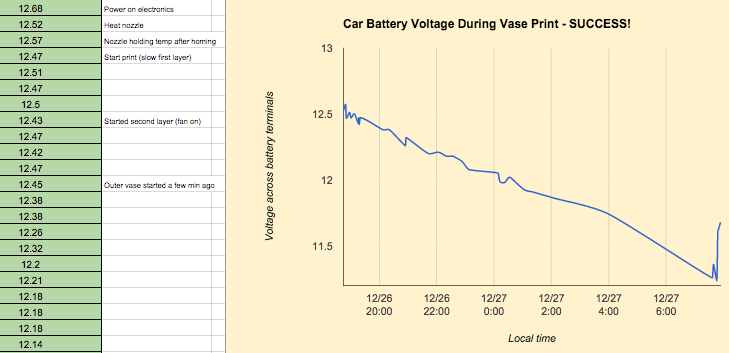
I had wired my multimeter in line with the positive line off the battery to read a super accurate space-rated amp-draw during the entire print. I had wanted to measure exactly how much was going in and out of the solar panel, and the battery. The measurement itself was actually resisting the flow of electricity (the equivalent of bending the water hose to hear if water is rushing past the fold in the line). Once I removed the multimeter and tracked only the voltage across the battery terminals, I was able to get over 13 hours of continuous printing time out of my Gigabot – enough to print this 300mm (12-inch) tall vase! Here are the (manually entered) data points for that one:
The solar panels are pretty straightforward, and work very similar to the battery charger I plug into the wall, so for the purposes of my experimentation in the garage, I’m alternating printing on battery power with a charger on/off, solar panel connected/disconnected, at varying voltage levels of the battery. I think I have found the limits, since my prints start failing at just about 11V on the battery now.
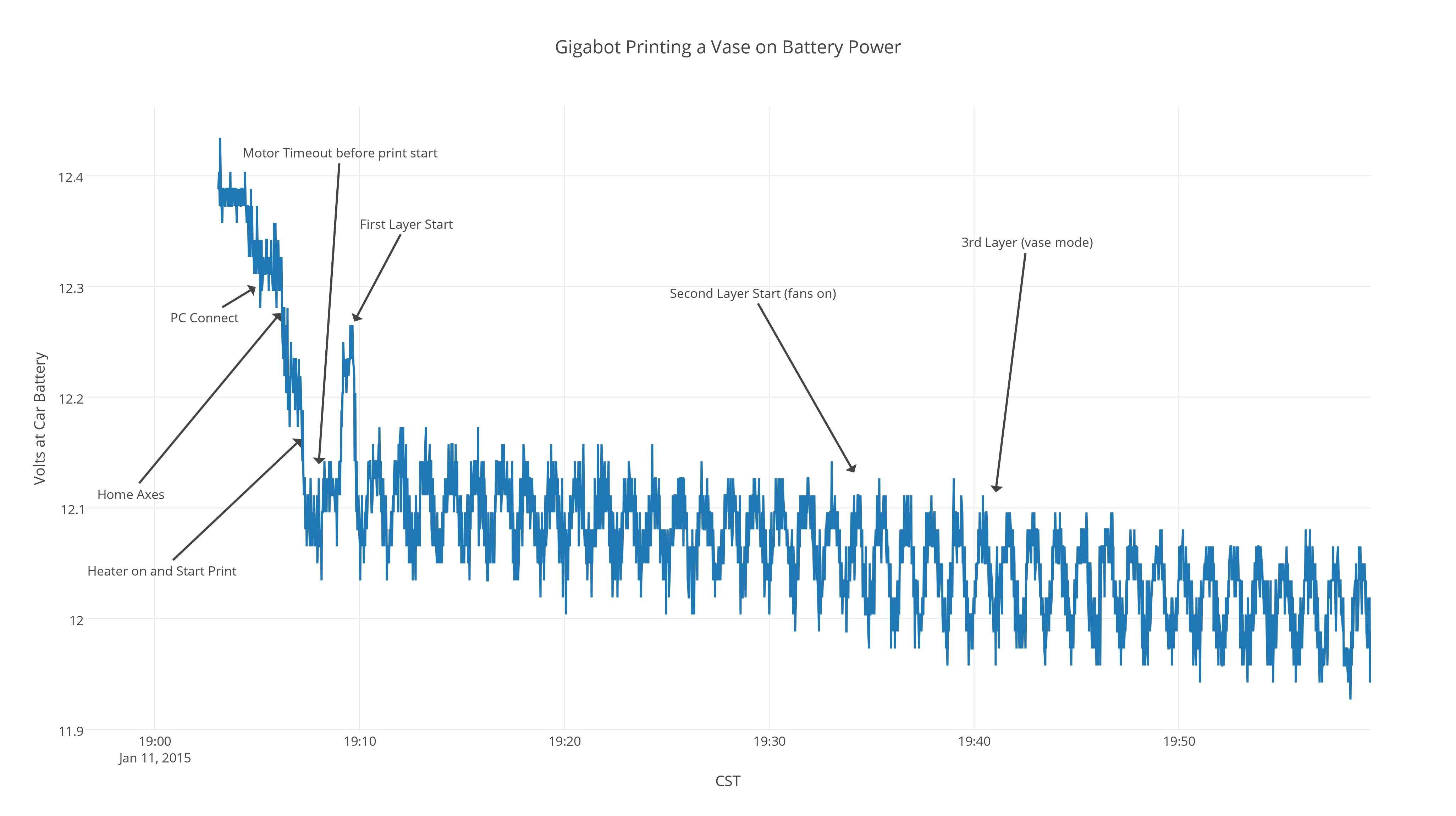
Also, ever since I automated my data taking process, I get much more sleep at once, without needing to wake up for data takes with pen and paper (and help from Google Sheets). Check out the new and improved version with a little help from plotly!
An interesting part of this method of gathering data is that you can start to see the cycling of the cartridge heater very clearly as the extra current draw pulls the battery voltage down each time the hotend is full-on. This will be useful in tweaking my PID values no doubt, and could also lead to better methods of insulating the hotend so it doesn’t need to heat up as much, thereby saving valuable amp-hours!
NEXT STEPS
Clearly there is a little more work to do before we have a brownout-proof or solar-ready Gigabot out of the box, but I think these experiments prove it’s within the realm of possibility to create 3D objects anywhere – given a robust enough printer, and a light bulb’s worth of energy and imagination.
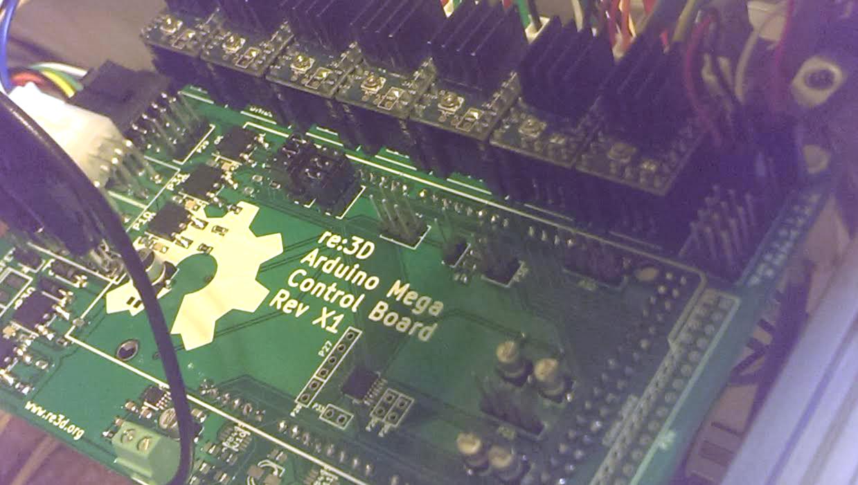
The new controller for OpenGB is loosely based on the open source RAMPS 1.4 control. The RAMPS 1.4 controler mounts on an Arduino Mega as an extension board (known as an Arduino Shield). The goal of the OpenGB controller is to include the following: motor driver for each motor, thermo couple and thermo resistor inputs, enough MOSFET power output for dual extruders, fan, and bed relay, endstops, and extra serial port terminals. This configuration keeps all of the active components on the professional board (arduino) and allows us to design with (mostly) with passive components.
The controller board will include the following features:
Stepper Motor Driver Sockets (7 drivers)
A total of seven motor drivers will be included, one (1) for the X-Axis, two (2) for the Y-Axis, two (2) for the Z-axis, and two (2) for extruders. The sockets are based on the Ti DRV8825 chip carrier board available from a number of suppliers and are currently used in the Gigabot 2.0.
The sockets will also add support for the fault and VREF pin on the Sure Step carrier boards. This will allow for better error detection and for programmatically setting the current of each driver.
Preliminary Motor Driver Socket Schematic
Thermocouple Support (3Circuits)
Two thermocouple inputs will be included in the preliminary controller. They will be based on the AD8495 chip.
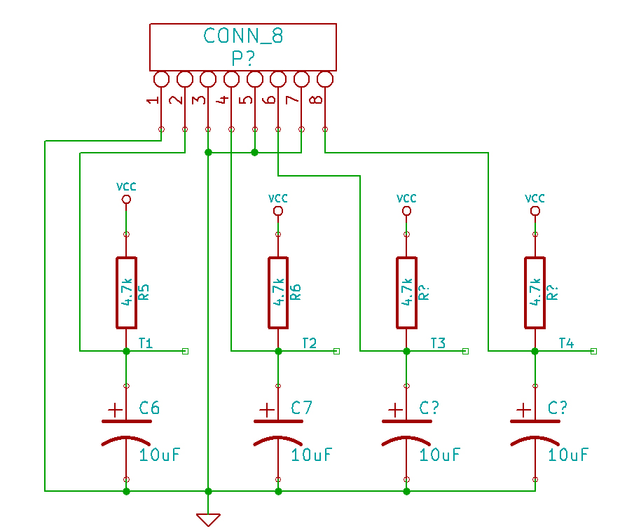
Thermo Resistors (4 Circuits)
Four thermo resistor inputs will be included in the preliminary controller. They can be used for controlling the temperature of the two extruders or monitoring the temperature at other locations on OpenGB. The inputs can also be used for other analog sensing needs.
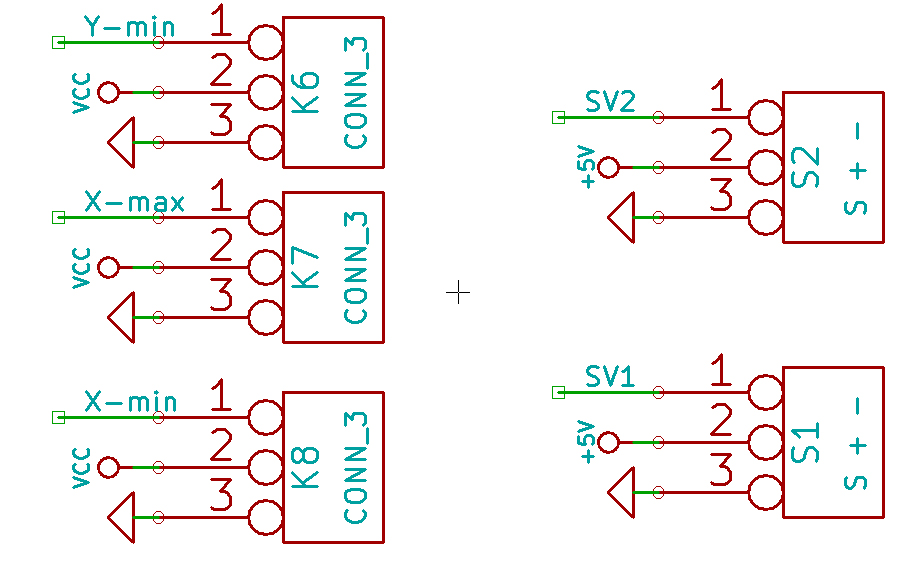
End Stop Terminals (8 terminals)
Eight (8) end stop inputs will be included in the preliminary controller. They will be labeled X-min, X-max, Y-min, Y-max, Z-min, Z-max, Filament Out, and extra.
Power Mosfets (4 circuits)
Four (4) power mosfets circuits will be included in the preliminary controller, based on the STP55 mosfet which is rated at 55 amps. Each circuits includes a indicator LED. The Circuits will be labeled Extruder 1, Extruder 2, Bed Relay, and Extra.
Serial Connections (2 terminals)
The arduino serial connection UART 0 and UART 1 will have terminals for easy integration. The SPI and I2C ports will also be broken out for onboard access.
These can will used in future iterations to avoid going through the USB hub with a direct UART to UART connection between the single board computer and the controller.
Reset Switch and Input
A reset switch will be included on the control board. There will also be a terminal block for an external reset switch. This switch should not be necessary for any normal operation.
Input for Induction bed Sensor
A single voltage divider will be included to enable the use of a bed touch less bed sensor to be used as the Z min limit switch
First revision is shown below, but I am assuming that it is going to change. After we test it I will post the design files, so you can take a look.
(note the image above is a concept image only and not a real design)
The OpenGB project gives us a chance to think about how to add design elements or change the Gigabot configuration to make it fit better in a home office setting. There are a few of us at re:3D that have Gigabots at home and also have cats, dogs, babies and whatnot. Unfortunately our loved ones don’t really use common sense when jumping on the Gigabot or nibbling on it to see what it might taste like. (I have explained to Mr. Squeakers that the Gigabot is not a cat toy / house, but he’s a bad listener. It is a character flaw.)
But anyway…
So at the preliminary design review we identified a couple of area to see if we can make less tempting for little hands or paws. What do you think? Do you have a cat that attacks your 3D printer? Let us know, email patrick@re3d.org.
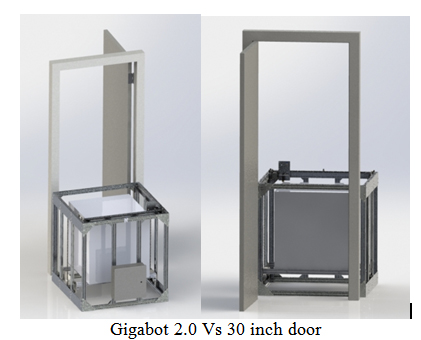
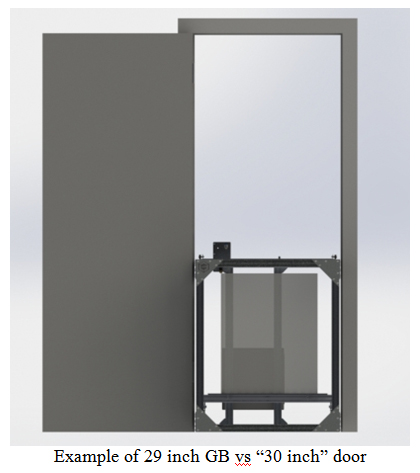
Because of it’s large print volume the Gigabot 2.0 does not fit through many interior residential doors. While there is some work arounds for this in a pitch, OpenGB is an opportunity to try to balancing shrinking one dimension of the Gigabot to less than 30 inches while trying to maintain the large build size. How big are your doors? Email and let us know, (patrick@re3d.org) My interior doors are around 30″, and searching Home Depot and Lowes doors seem to be 30″, 32″, and 34″. But there doesn’t seem to be a standard (for internal doors).
At re:3D we are constantly evaluating opportunities to integrate open platforms and philosophies into our company & products. From the firmware that interprets Gigabot’s G-code, to 3D Thursday Google hangouts with our Kickstarter backers, we recognize that the best way to operate is by partnering with our community. With that in mind, we are experimenting with an iteration of our Gigabot open source design with an eye toward the Maker, the Tinkerer, and the Educator. We want to enable home or school-based manufacturing in a way that reflects today’s trends of openness, iteration, and personalization while solving some challenges you have shared.
Throughout this process, we’re learning a lot. Not only about 3D printing, but about how people create things, and what their challenges are. So in the coming weeks we would like to share this experience of gathering user experiences, and solicit as much feedback as we can from the tinkerers who have ideas and thoughts to share. We are also researching different ways to approach manufacturing, so you may see some alternatives to our current, low-volume approach that you see today in Gigabot.
Our aim is to align this version of Gigabot with the philosophies of the new industrial revolution that we see ourselves within. Customizable – yet having standardized interfaces. Modifiable – yet with a clean design. We want “Your Gigabot” to continue to be a melting pot for multiple industries, but have some specialized features that really take advantage of the size, and the diversity of input material.
The “experimental version” of Gigabot which we are currently calling “OpenGB” is designed to be built with open source development boards like the Arduino, and Beagle Bone. It will also explore solutions to some challenges our home based users and those collaborating on 3D printing projects have shared. We think there might be a better name than OpenGB, but haven’t found it yet. We’re are hoping you will have some ideas.
This Gigabot has been inspired by the feedback & needs of our hobbyist hackers. As we adventure into an even more open Gigabot, we feel it is important to share our plans, and collect your inputs along the way. We invite you to check out our blog for project updates and to contact us directly with feedback at engineering@re3d.org!