Crazy 3D Prints: Making a Ping Pong Paddle

What do 3D printing, a table tennis, Gigabot and PETT have in common?

An amazing use case for custom, functional outdoor prints!

Until recently, printing large objects on FDM 3D printers was limited to small scale objects subjected only to controlled, room temperature environments. However, with the introduction of high strength materials like those offered by 3D printing filament expert taulman3D, making functional objects that can weather the Texas heat is now a possibility.

Enter t-glase. This material prints like Bridge Nylon, but with almost no shrinkage. You can learn more about the main features of t-glase on the taulman3D website. We heard about t-glase during a call with Tom Taulman when we shared a need of another local start-up seeking to 3D print custom table tennis paddles. Originally they attempted to 3D print their original design at the University of Texas. After several failed attempts to fit a set of paddle parts on a desktop printer, a local professor suggested they speak with us. In our conversation, we learned a lot about table tennis and the amazing potential 3D can offer those looking to customize paddles!
 
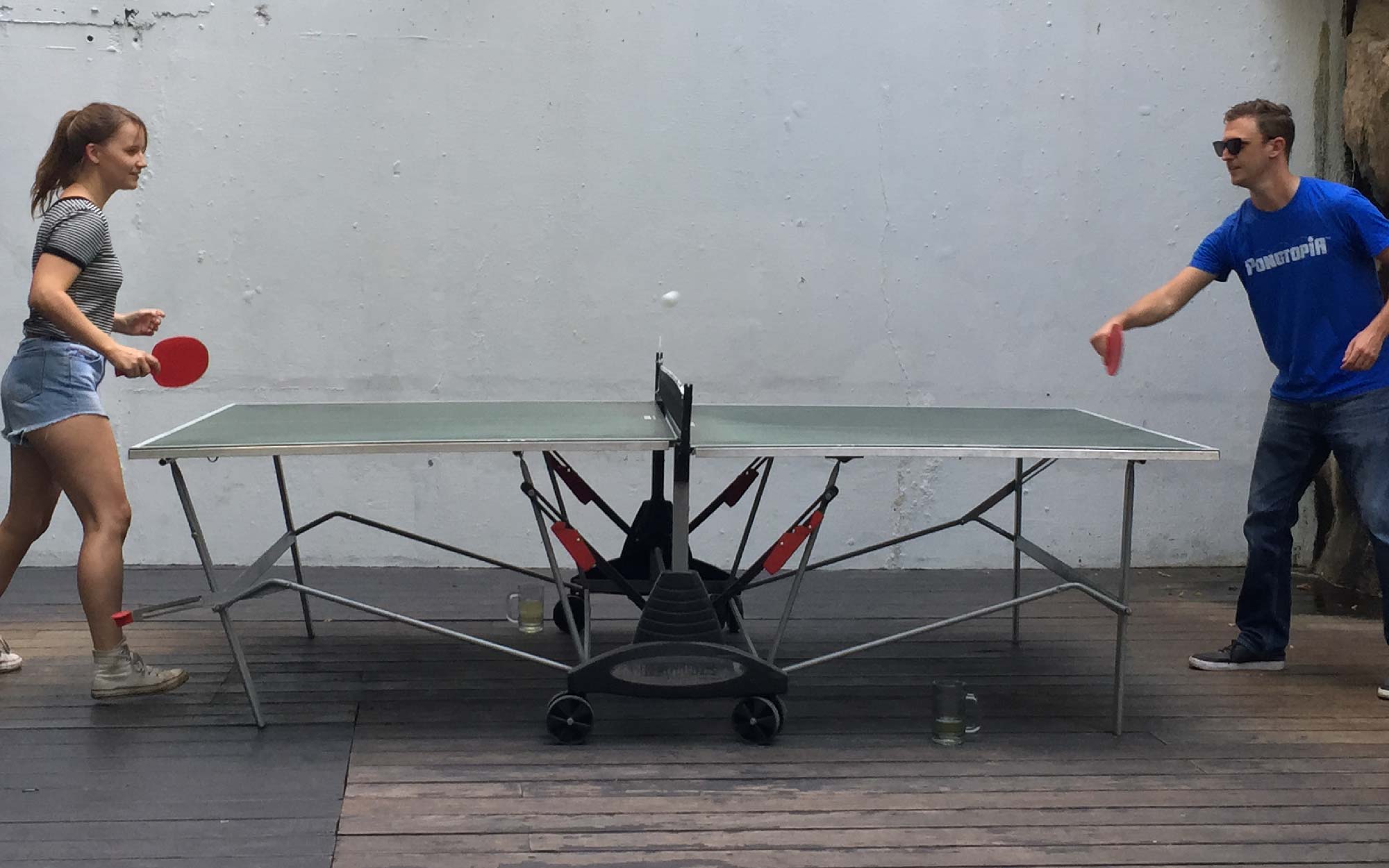
Uberpong™ makes custom ping pong paddles by blending art and design with the sport in a revolutionary approach that goes beyond the game itself. Uberpong also introduced us to Pongtopia, an app to find ping pong tables around the world. As you can see on Pongtopia, table tennis is played both inside & outside, suggesting that in addition to needed a high strength material with a little give, we also needed to source a material that wouldn’t warp or crack in heat or cold playable weather conditions. This would be similar if we were printing a regular sized tennis racket that would be used by a tennis coach for beginners sessions for example, so it’s good to bear in mind the material that needs to be used must be hard wearing.
 
In support of the experiment to see if ping pong paddles could be successfully printed on Gigabot, Tom shared some red t-glase samples. We printed Uberpong’s original ping pong paddle 3D design at our Houston office on Gigabot live during our June Open House with Hubs. It was an awesome opportunity to have 3D printing veterans weigh in on the outcome & settings.
 
The experience was hugely educational. As seen on the paddle on the left, I originally forgot to use a glue stick on the print surface to increase adhesion. Also, initially I printed a little too low at 225 degrees Celsius. After getting some guidance from the t-glase webpage, I increased the temperature to 235 degrees Celsius which resulted in a better finish. Using 235 degrees Celsius and a glue stick, the second paddle turned out great. Unlike the paddle on the left, which has a slightly rough temperature until I increased the temp and curling from the lack of a glue stick, the right was firm, glossy and completely flat.
 
With the paddles complete I drove them to our Austin office, which is nestled downtown near Pongtopia. We agreed that the next step would be to find a proper table tennis facility to test the prints. Using their app, we discovered Easy Tiger, a casual hot spot with multiple tables set up on their patio. Prior to meeting up, I took the initiative to glue the handles together with Gorilla Glue, and press them in a vice overnight. While the adhesive was plenty strong, I neglected to consider the foam that Gorilla Glue inspires, so as you will see in the videos below, the paddles were a little less aesthetic than they could have been with clear superglue!

After playing a match and drinking a couple of pints of cider at Easy Tiger in Austin, Rebecca and Dave shared their musings on the paddle performance and applicability for 3D printing in table tennis.

Overall, despite my adhesion and profile hiccups, we give taulman3D’s t-glase two thumbs up! We’ve even decided to resell t-glase on our shopping site! The ping pong paddles were firm, but offered a slight give. Despite the 100 degree Farhenheight Texas heat, we weren’t worried about the paddles deforming in the rays. This new material gives table tennis players worldwide a unique opportunity to customize their paddles. We can’t wait to follow Pongtopia and see how 3D printing and this industry evolves!

Want to chat with the users? Reach them here:

  • David Lowe at Uberpong/Pongtopia: dave@uberpong.com
  • Rebecca, a Gigabot Ambassador: rebecca@re3d.org

Looking to chat with the t-glase wizard?

  • Tom Taulman- taulman@taulman3D.com
 
Happy Printing!

Samantha Snabes

Blog Post Author

Getting a Grip : Part 1

Getting a grip on your 3D printer filament-Part 1

With the rise in popularity of low cost 3D printers for use in homes and small business many new printer designs have recently arrived in the market. The cost of ownership for 3D printers is coming down which is driving up access in new markets. With a customer base growing outside of engineers and tinkerers it is important that 3D printers must remain near 100% reliable with near zero failed prints due to mechanical and electro-mechanical malfunctions.

One of the leading causes of print failure is the filament feeding mechanism. By surveying the literature and leveraging our current experience in hardware development we have identified a gap in the knowledgebase for understanding the mechanics and operations surrounding the extruder drive gear commonly used on FFF type 3D printers.

We have found reliability of the filament feed gear is dependent upon three factors 1) amount of contact surface are between the drive gear and the filament, 2) depth of the gear’s tooth engagement into the filament 3) number of teeth engaged in the filament at any one time and 4) the direction of the force vector imparted from the filament drive gear into the filament. R&D at re:3D delved into this problem and below is result of their work.

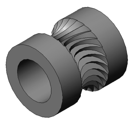
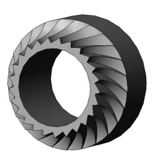
Figures 1 and 2 below shows a 3D rendering of the filament drive gear “Jaws” that will be mounted to the shaft of a geared NEMA 17 stepper motor.

Figure 1. Jaws filament drive gear. Figure 2. Mid-section view of Jaws filament drive gear

The Jaws filament drive gear is machined using a four axis Bridgeport CNC milling machine. In the design process our aim was to optimize the four variables stated above.

  • The amount of contact between the drive gear and the filament is maximized by machining the gear teeth using a cutting tool of the same diameter as the filament it will drive. In our case the filament is 6.0mm in diameter.
  • The depth of tooth engagement was optimized by balancing greater tooth engagement with number of teeth engaged into the filament at any one time. If the tooth engagement is too shallow there will be too little surface area and force imparted to the filament and the teeth will slip and shred the filament. If the tooth engagement is too great the risk of plastic deformation causing the filament dimension to be out of spec for the hot-end and will cause jamming of the hot-end during printing.
  • The number of teeth engaged into the filament at any one time is important in maintaining a smooth and constant push of filament into the hot-end. Consider the job of the filament drive gear is to transform the rotational motion from the stepper motor into straight line movement of filament into the hot-end. If too few gear teeth are engaged into the filament the linear motion of the filament over time will assume more of a sine wave pattern than a constant straight line movement.
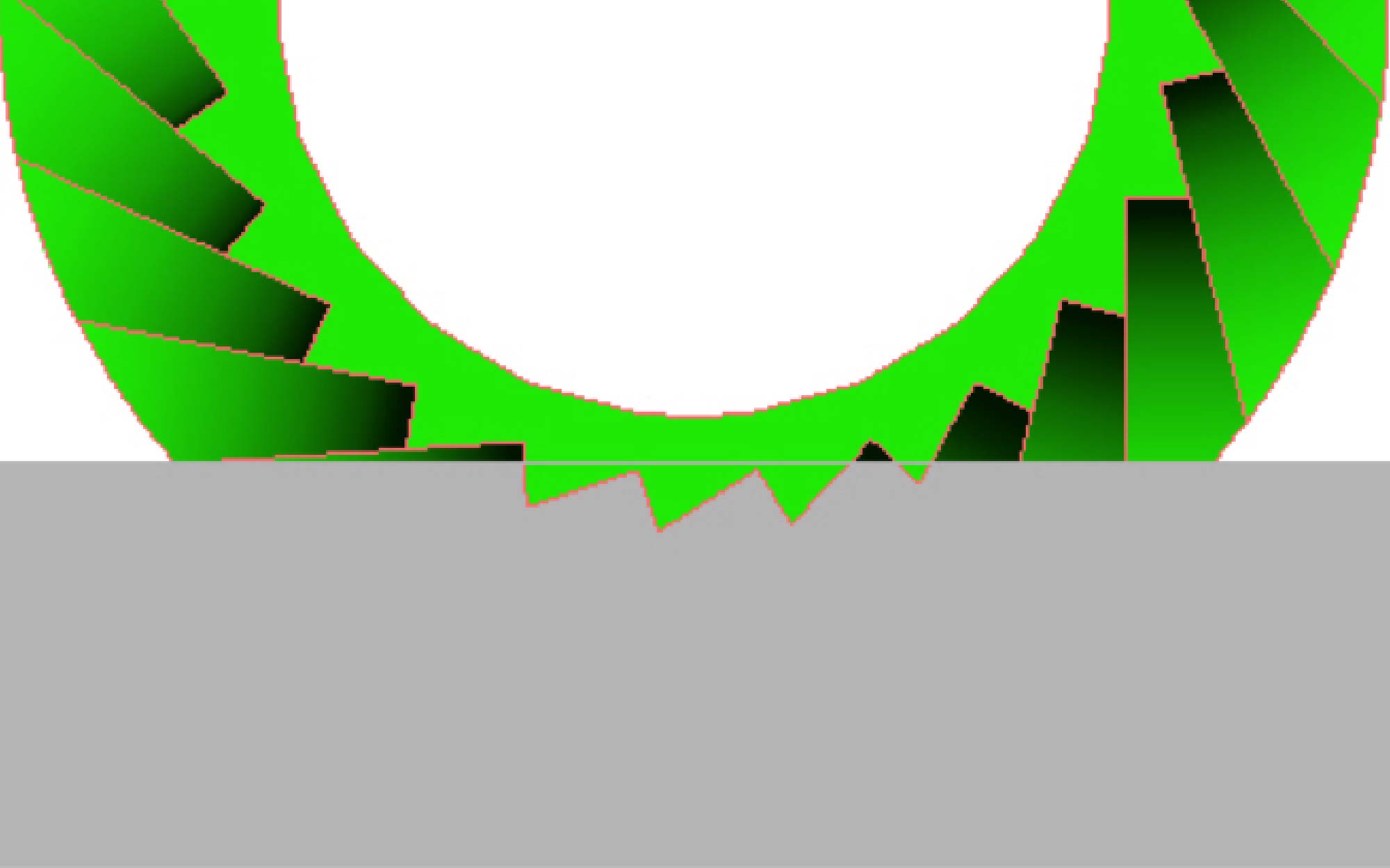
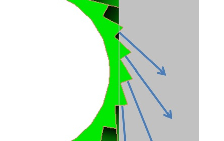
  • The force vectors should be directed in the downward direction as much as possible to increase the conservation of energy in the system. Any forces imparted into the filament in the lateral direction will cause plastic deformation of the filament and not translated into pure downward force of the filament feed. It should be noted there will always be a certain amount of lateral force experienced for the pure fact that the drive teeth will need to be engaged into the filament. By studying the section view in Figure 3 below you can see the depth of engagement, the number of teeth engaged and the force vector for a 25 tooth drive gear.
Figure3 Force vectors
Figure 3. Tooth engagement, number of teeth engaged and force vectors

We are extremely excited to have optimized the design and manufacturing of this advanced filament drive gear for FFF style 3D printers. You can view a short video of the machining process on our re:Tech YouTube channel:

Stay tuned for part two in this series where we will perform data collection and force measurement in a real world application of the Jaws filament drive gear.

Matthew Fiedler

Blog Post Author