re:3D was on the move last year – literally. But the crew has settled into the new Austin facility with a continued passion for tackling the challenges of additive manufacturing. New faces have joined the Engineering and R&D Teams, and they have all been making impressive progress during the sometimes messy results of a relocation. This is a long-overdue look at some of their recent work.
Early last year there was a company-wide exploration of how and why ‘filament grinding’ was affecting our customers. Follow-up work has focused on cooling methods – both for the extruder mechanism and for part cooling. Improvements in cooling the extruder heat break reduces filament softening (i.e., “heat creep”) in low-temperature materials such as PLA which is a contributing factor to grinding and ultimately print failure. Other thermo-mechanical properties of the extruder are being evaluated as well, with the goal of better thermal management of the filament for more reliable extrusion. Upgrades to part cooling are also being tested. For many thermoplastics, the goal is to extrude above a certain temperature and let the polymer bond to the previously deposited layer (if there is one), and then solidify to maintain the desired geometry as the nozzle travels onward. The rate at which the plastic hardens affects how fast the nozzle can travel without compromising the quality of the print. Often, by appropriately cooling the extruded plastic with forced air, the plastic still bonds, but the geometry is rapidly set and the nozzle can travel faster – ultimately completing the print more quickly. Rapid setting of the polymer also allows for improved performance when printing bridges or overhangs.
With a new approach to thermal management, small, square axial fans are still used to cool the extruder heat sinks, but radial blower fans are used to provide higher-velocity air at the nozzle tip for part cooling (Figure 1, left and center). With this approach, unsupported overhangs of up to 70° are achieved before scoring “poor” using standard overhang print tests. Print speed can also be dramatically increased. The cooling upgrade allowed a standard 3DBenchy model [1] to be printed in 32 minutes with good quality (Figure 1, right) – down from 70 minutes.
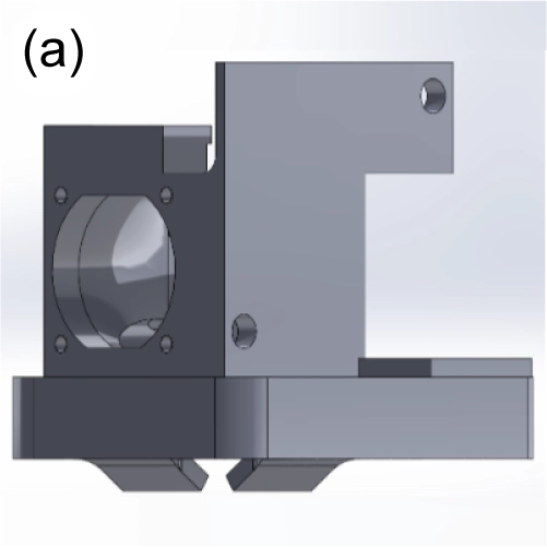
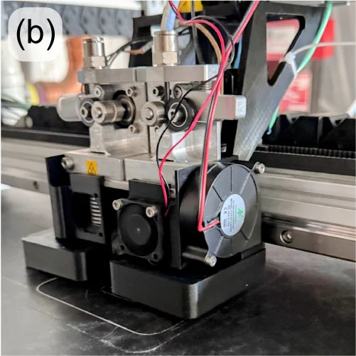
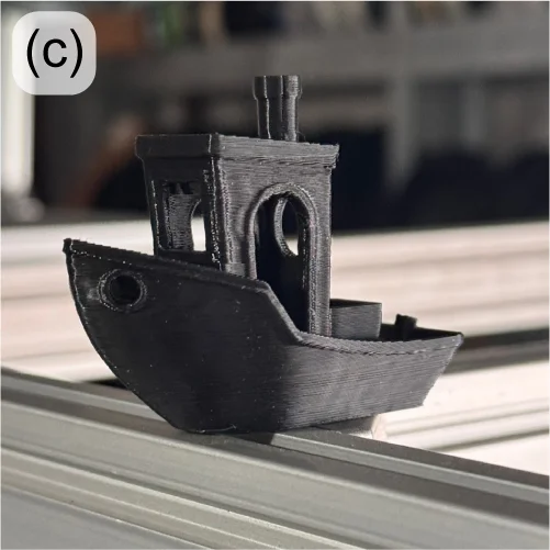
Figure 1: New Gigabot extruder cooling design under test (a-B); 32-minute 3DBenchy printed using upgraded cooling (c).
The Engineering Team is also responding to the re:3D user community’s request for a conversion kit to use 1.75mm filament on their Gigabot printers. The new dual-extruder design has been extensively tested on multiple materials internally and will be sent to external beta testers soon.
Product development on the GigabotX (GBX) in recent months has been focused on a mount for a bed sensor to incorporate bed mesh compensation software correction, along with an implementation of part cooling for the GBX extruder. Bed mesh compensation will be performed with the same eddy current sensor now under beta test on the Gigabot filament machines, but the design challenge is to create a mechanically stiff mount at the end of the long extruder system. As part of this mount, cooling fans and ducting are being incorporated to provide forced-air part cooling. The reasons for part cooling are described above, but with the larger bead sizes on the GBX, the thermal mass of the extrusion is generally larger, and the need for part cooling is even more critical – especially for bridging and overhangs. It can also promote easier breakaway of support material from the print.
With the part cooling design now under test (Figure 2), PLA is bridging over 40mm with minimal drooping (Figure 3, left) and able to create acceptable bridges and spans over 100mm (Figure 3, right). Overhangs are also improved, and support structures more easily break away by hand, leaving clean parting surfaces.
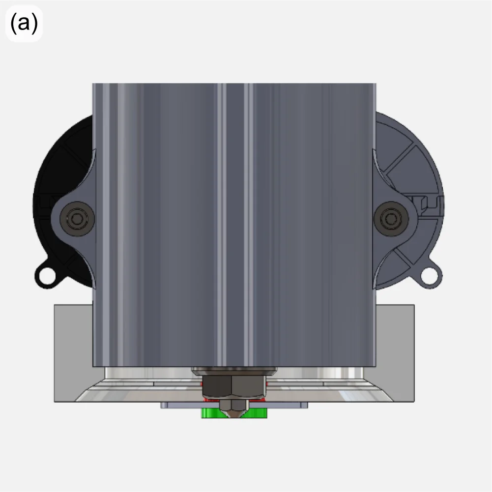
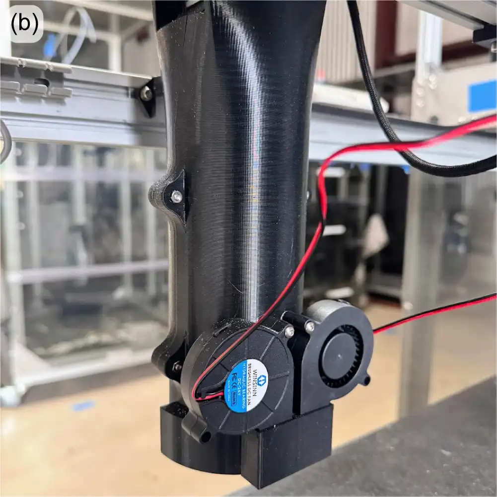
Figure 2: Experimental mount for a bed sensor on the GBX extruder shown in green (a); GBX part cooling fans attached to the back of the extruder cover (b).
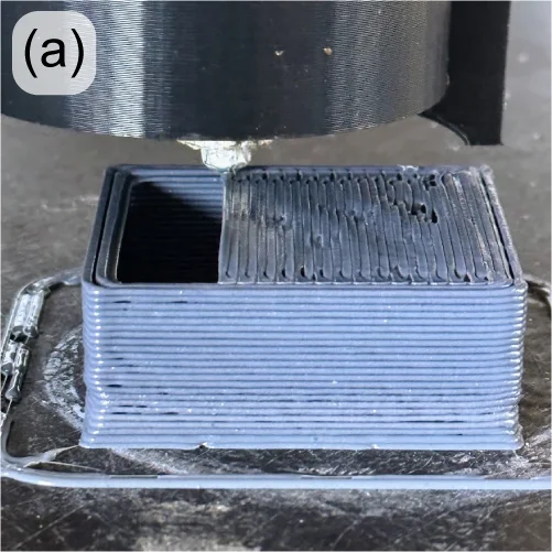
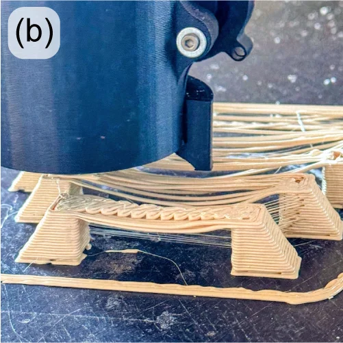
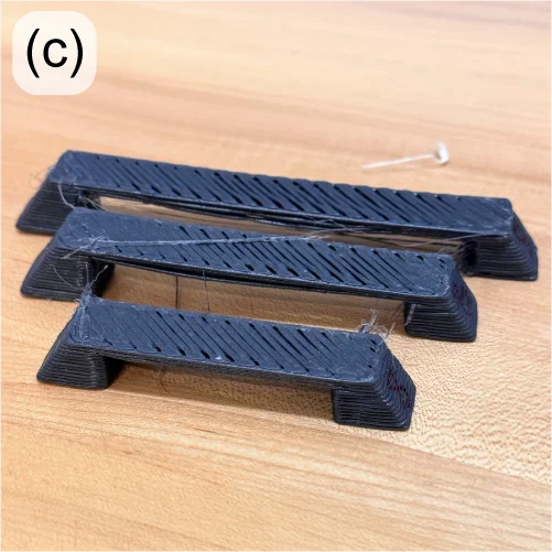
Figure 3: 60mm bridging with part cooling on a GBX (a); poor bridging and spanning without part cooling (b); good bridging and spanning over 100mm with part cooling (c).
At the other end of the extruder, improvements are underway to improve the reliability and consistency of material throughput. The extruder motor is connected to the extrusion screw through a jaw coupler, which uses a polymer spider interface between two hubs. If overheated or over-torqued, this spider can become deformed, potentially affecting extruder performance. This style of couple also allows for undesirable axial motion of the extruder screw. A new disc coupler is being tested with good results (Figure 4).
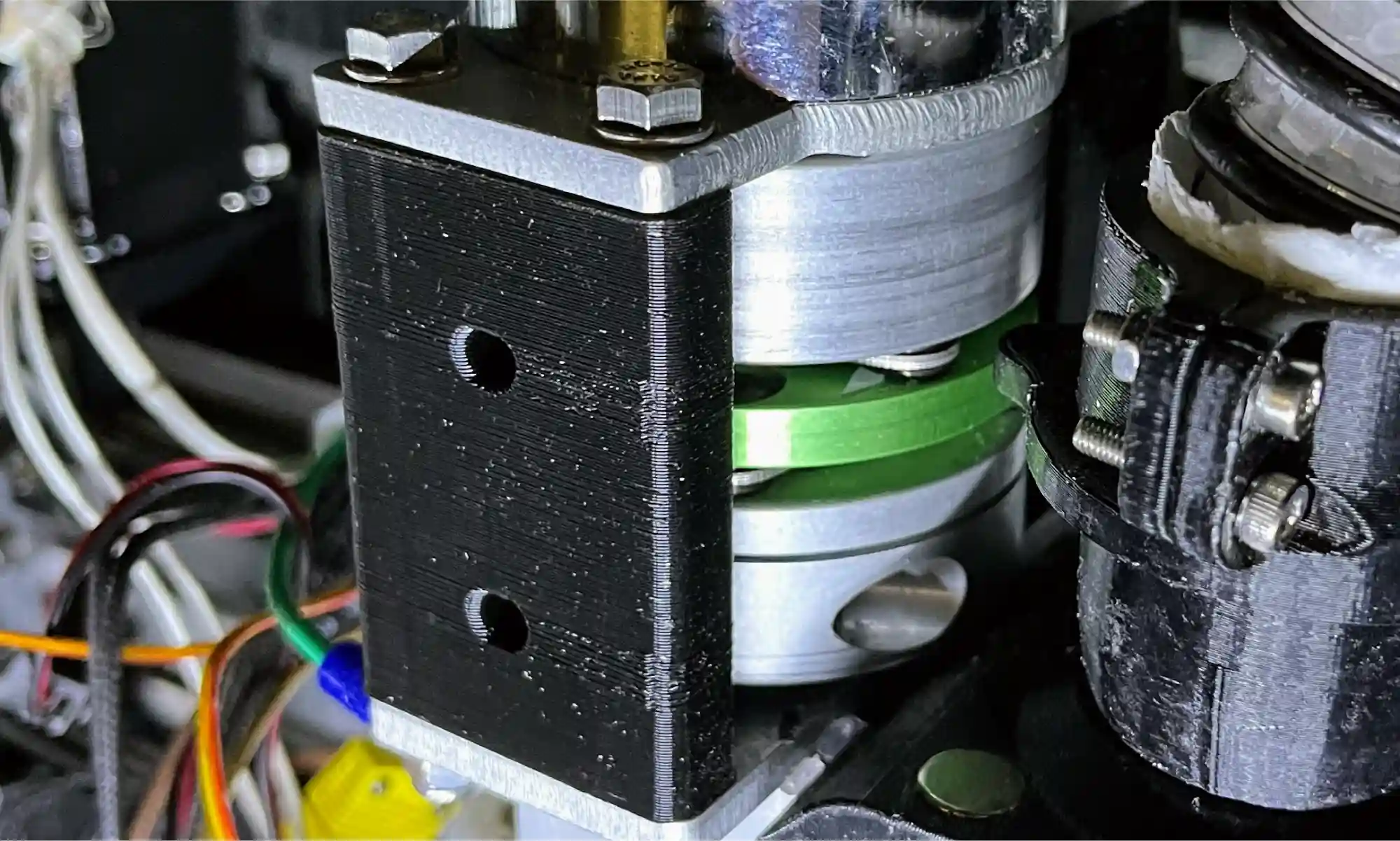
Figure 4: New GBX disc coupling under evaluation.
Throughput problems can also be caused when the feedstock (pellets or flake) bridges within the input to the extruder. This material bridging (buildup, jamming, etc) introduces inconsistencies to the flow of material into the extruder which results in underextrusion.
This is more pronounced when using feedstock with irregular morphology and low apparent density (e.g. granulated water bottles), which do not pack tightly or flow well into the extruder under gravity alone.
To address this, over 40 versions of a “crammer” that actively feeds material into the extruder have been tested over the years, with the current version called the “beta” crammer (Figure 5). This crammer successfully reduced inconsistencies in the extrusion rate, successfully printing rPET flake at the same rate as rPET pellet. While the crammer showed great potential for printing with irregular flake, unfortunately material bridging still happened upstream from the crammer (at the hopper-hose and hose-barb connections). To take full advantage of the crammer’s abilities, it is important to design a system to reliably resolve material bridging in the feed tube.
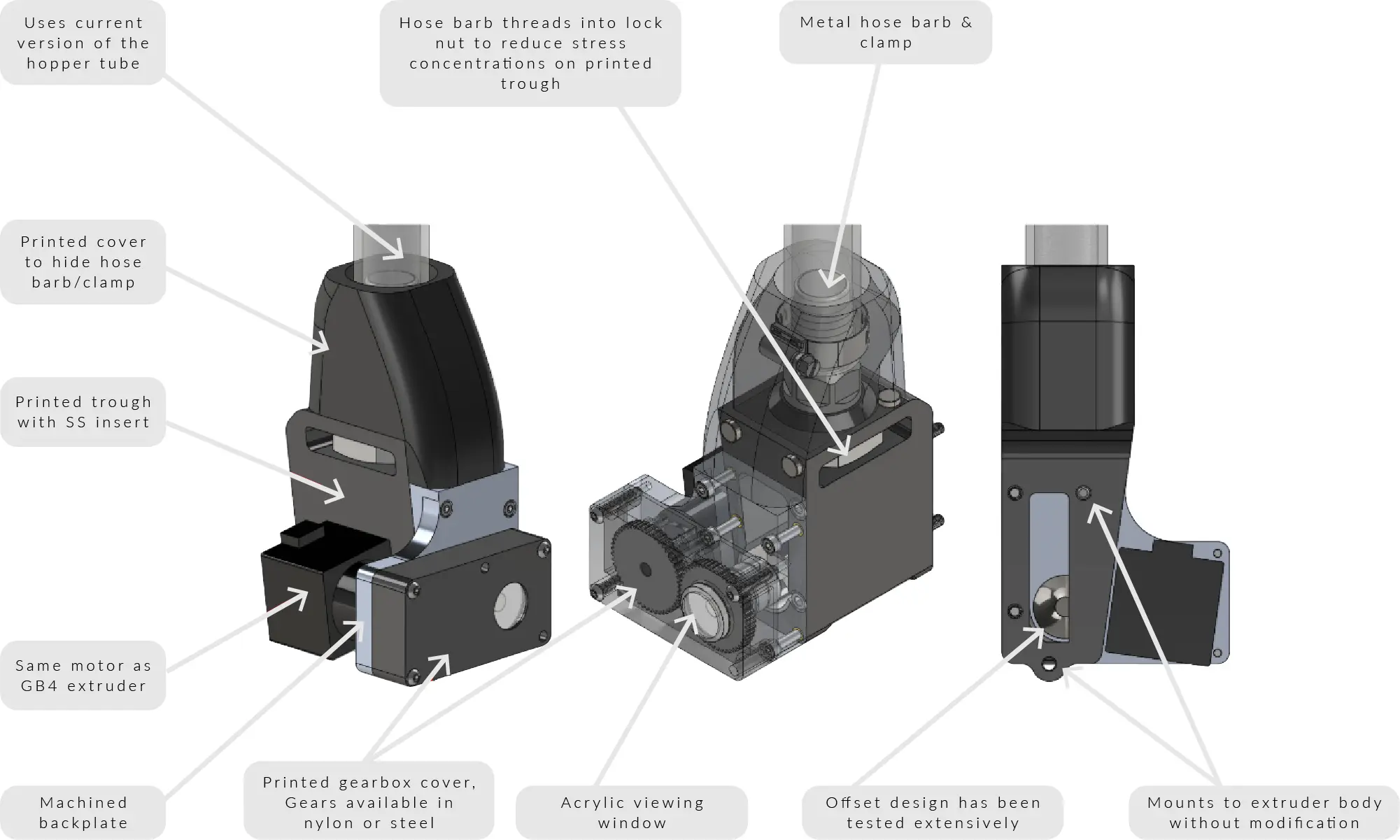
Figure 5: Current ‘beta’ crammer design.
The most important recent design change to the crammer has been to the feedstock hose clamping mechanism. The tubing was originally connected using a metal hose barb and a worm gear hose clamp, similar to garden hoses. Because the hose barb fits inside the hose, the diameter of the feed path decreases at the interface, creating a stepped region that is very prone to material buildup. To address this issue, the hose barb has been replaced with two printed parts that secure the hose from the outside using screws (Figure 6). The new hose clamp design has been tested for well over 100 hours, and showed zero cases of material bridging with all pellets and most flake feedstocks. The flakes that still showed some trouble, including granulated plastic ID cards and shredded water bottles, had particularly irregular morphology due to its original thin thickness.
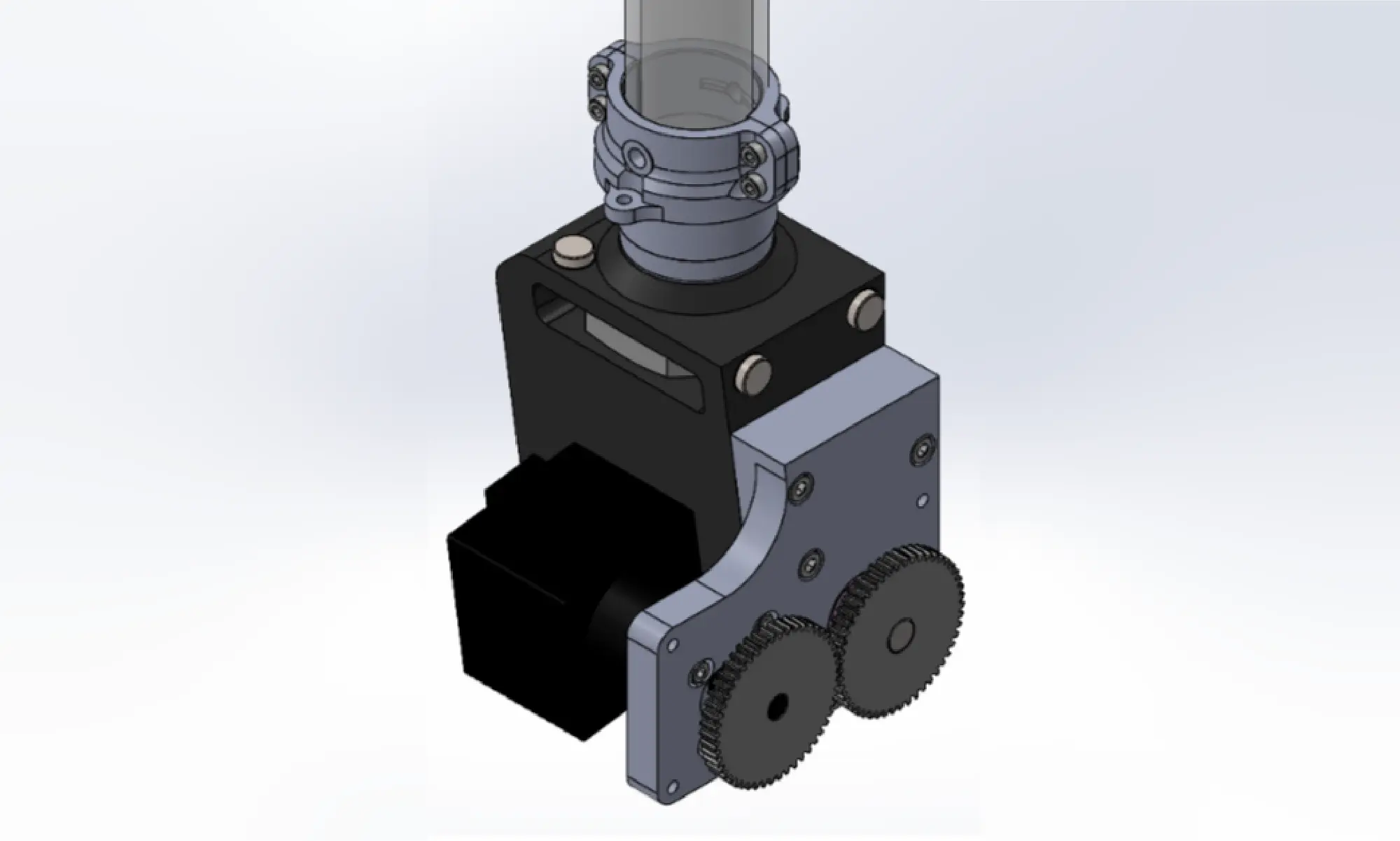
Figure 6. CAD image of new hose clamp design.
For feedstocks with more extreme morphologies, multiple solutions have been considered, including fluidized beds and vibration motors.
The fluidized bed system designed by Dr. Christopher Pannier’s team at the University of Michigan-Dearborn [1] sends compressed air upstream from the feed throat (Figures 7 and 8). With the right combination of air pressure and flow rate, it is possible to create an environment where solid particles behave like a fluid – a “fluidized bed”. Under this condition, flakes can flow freely through the path without building up on top of each other. Dr. Pannier’s team has tested this system to identify appropriate combinations of air pressure, air flow rate, and duty cycle that produce ideal fluidized bed conditions. However, as of today, only one material of controlled sizes (granulated rPLA, sifted 2~3mm) has been tested. To replicate similar results and identify combinations of parameters for other materials and feedstock morphologies, extensive testing is required.
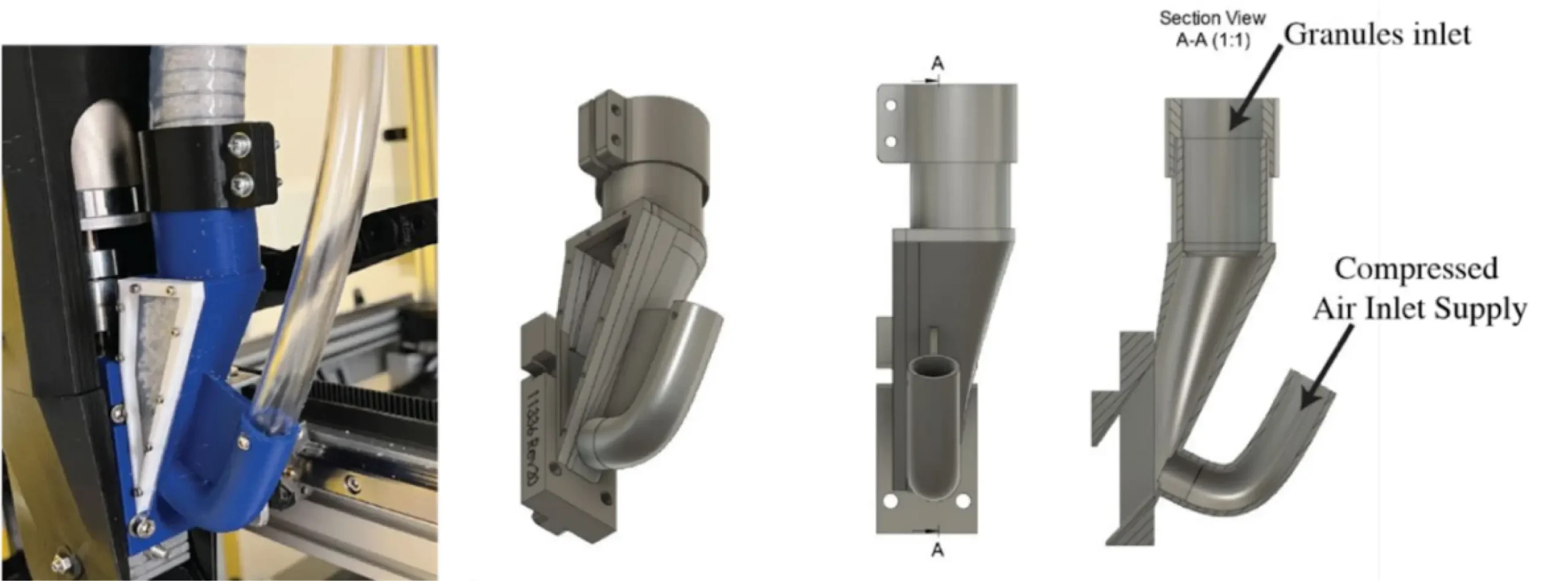
Figure 7: Fluidized bed system implemented on a GBX. (Image credit: Pannier, 2023)
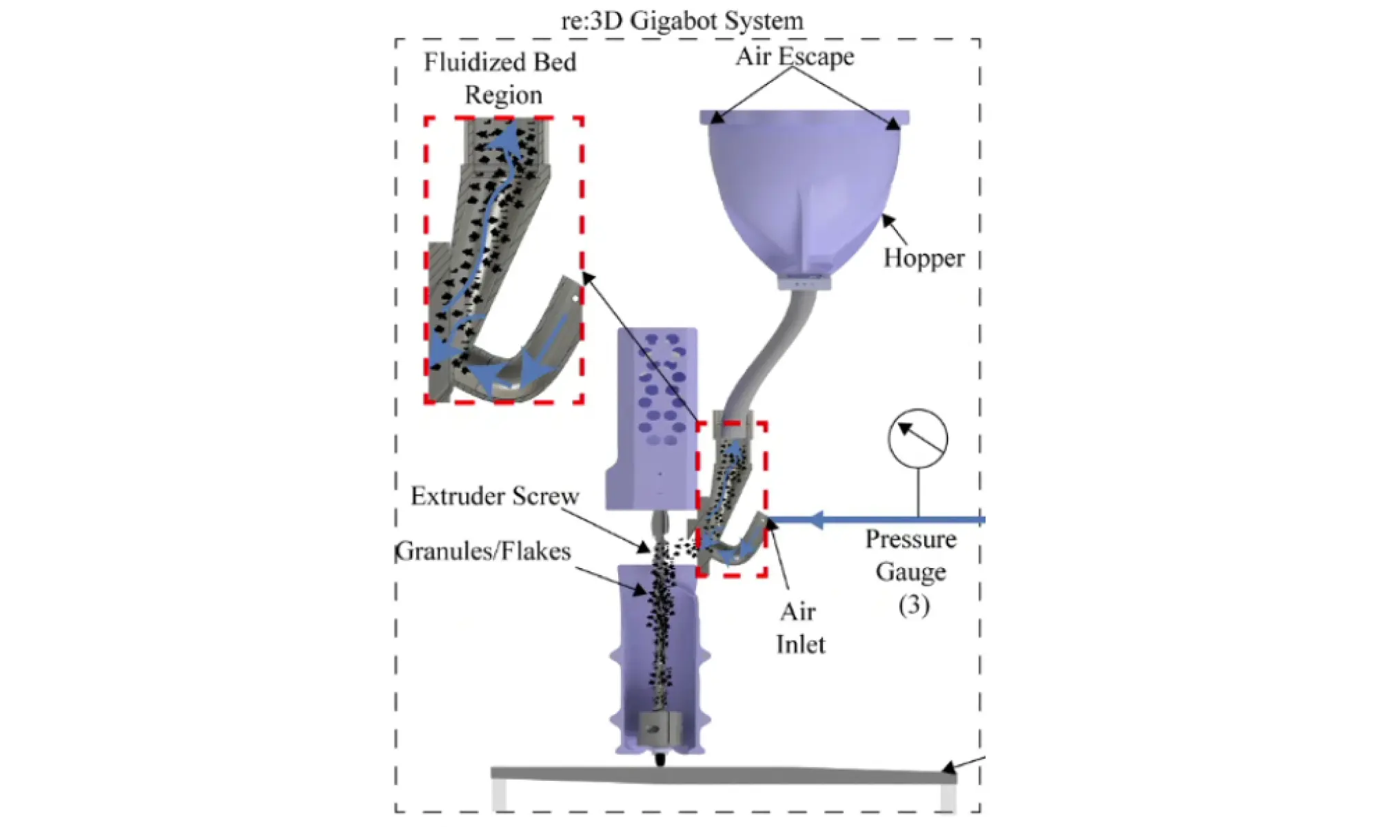
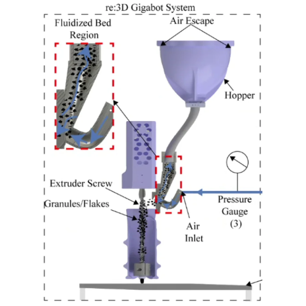
Figure 8. Fluidized bed system configuration. (Image credit: Pannier, 2023)
Another option to reduce bridging is simply attaching one or more motors to the feed tube, generating vibrations or impact to remove buildups. There have been previous investigations into this solution at re:3D between 2021 and 2022, but the team faced issues including vibration-induced fatigue failures in wires and the printed feed throat. Eventually, this idea was abandoned as the team started to focus on the development of the crammer, which increased the throughput of the machine considerably. The vibration motor system helped with the consistency in extrusion rate by breaking up material buildup, but had little to no effect on the extrusion throughput. The vibration motor system could potentially be a great partner for the current crammer system, as they complement each other and address separate issues. The vibration motor system is not only a simple and cheap implementation, but also does not require major modifications to existing parts.
In a recent re-investigation of the vibration motor system, the motor was mounted directly onto the hose – independent from the extruder body or the crammer – such that the vibrations do not affect other systems negatively. Because constant operation of the motor may cause overheating and also accelerate vibration-induced fatigue, the motor was operated with a duty cycle using custom G-code or external python scripts. Quick testing showed promise, as even short bursts successfully broke up any material buildup along the hose. While no quantitative tests were conducted, the effect of vibrations were easily visible through the transparent feed tubing and also on the printed parts that lacked telltale signs of bridging-induced underextrusion (Figure 9). For the vibration motor system to be implemented, it will require a more robust mount design that reduces the noise (currently 50-60 dB) and secures the motor while sustaining vibrations over an extended period of printing time.
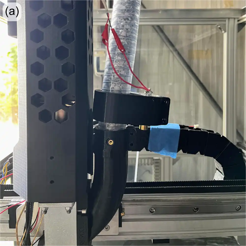
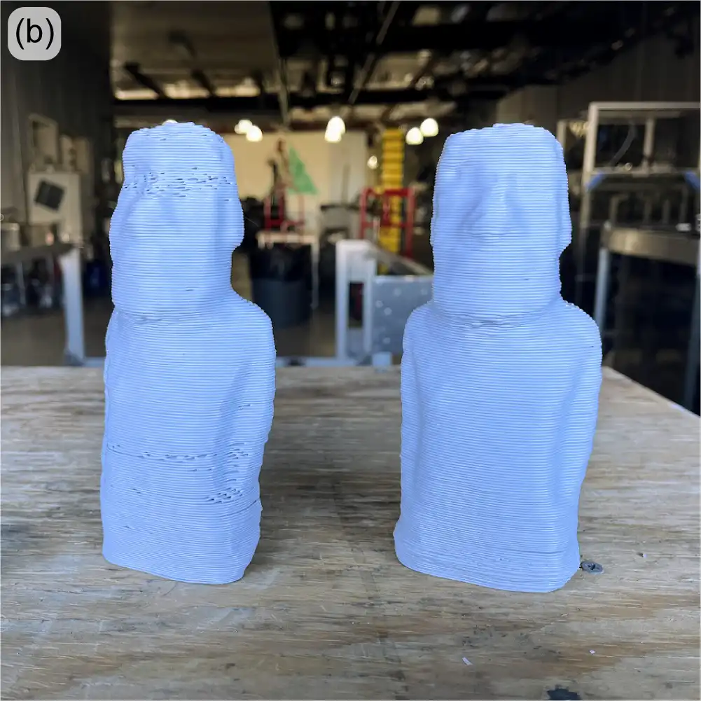
Figure 9: Vibration motor attached to GBX feedtube (a); recycled polycarbonate prints without and with vibration motor activated (b).
For now, a few minor tweaks to the ‘beta’ crammer have resulted in reliable and consistent extrusion performance for most feedstock materials and morphologies. But it’s good to have experience with additional options should the need for additional bridging mitigation arise.
Software Improvements
The software team at re:3D is incredible. Their most recent work to improve customer experience with the Gigabot and GigabotX printers includes bed mesh compensation, the new Klipper stack V0.5.0, improved print recovery, and a new web application: Helm.
Mesh Compensation Enhancements
Reliable printing requires reliable, high-quality first-layers. One key factor to a successful first layer is proper bed leveling, or more properly, bed tramming. Manually leveling the large print beds on the Gigabot and GigabotX printers might take a bit of practice, but the system does remain stable – until heat is applied. When materials (especially metals) heat up, they tend to expand. Depending on the mechanical constraints on the object, its shape will change. In the case of a flat metal plate with fixed constraints as shown in Figure 10, heating a print bed can cause bowling or warping at these elevated temperatures. No matter how much you try to “level” the bed, the print nozzle will not remain a constant distance from the bed surface without active correction.
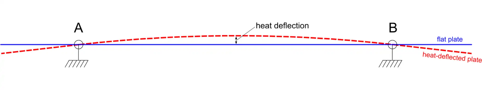
Figure 10: Depiction of thermally-induced deflection of a mechanically constrained bedplate.
Enter “mesh compensation”. In this method, a map, or mesh, of the now-warped bed is measured with a sensor. This heightmap (Figure 11) can then be used in a mathematical algorithm to correct for changes in distance between the nozzle tip and the bed surface, and the firmware will automatically adjust the z-axis height to maintain the appropriate “height”, leading to improved first-layer adhesion, consistency and overall quality.
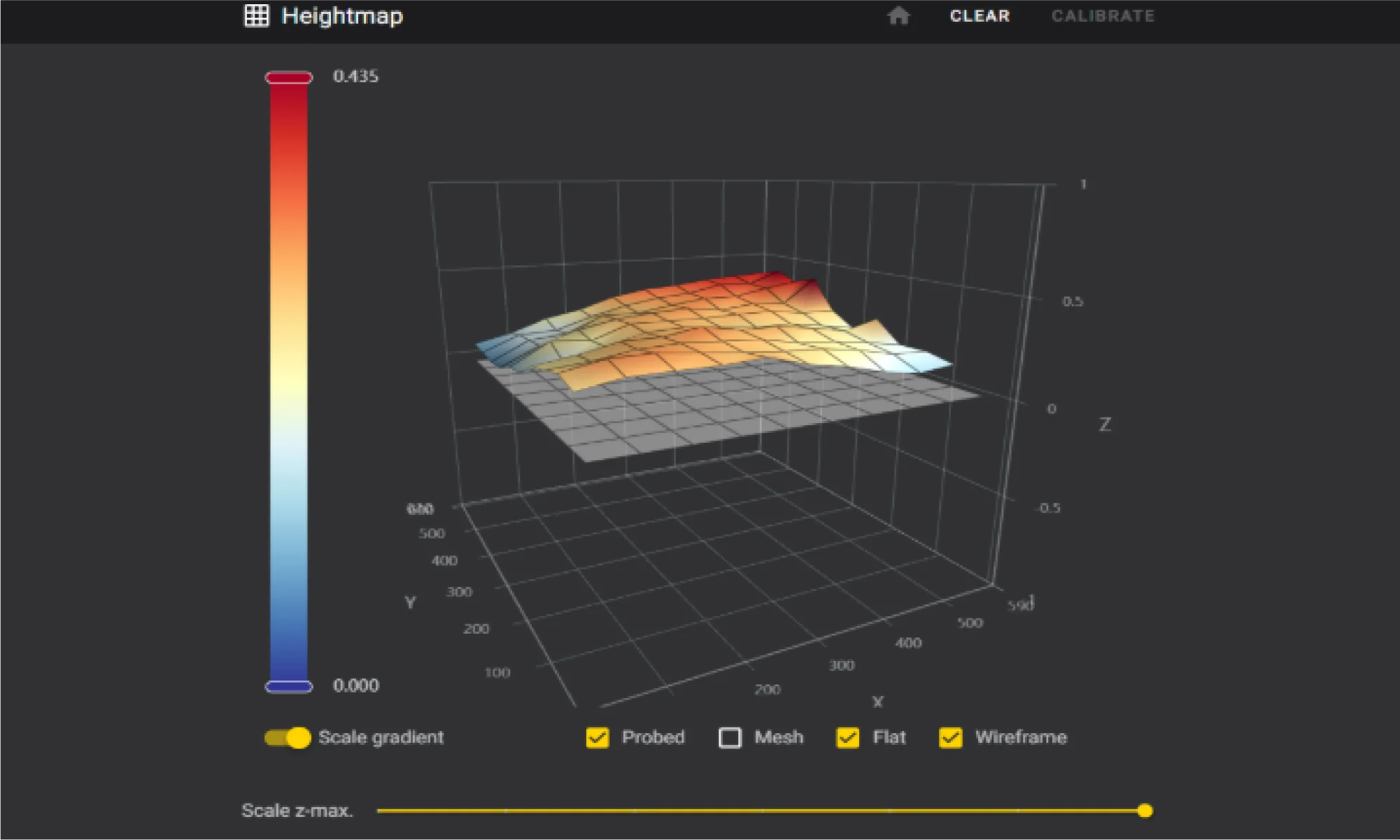

Figure 11: Bed heightmap generated from the eddy current sensor and bed mesh compensation software.
The team has been working hard to perfect mesh compensation to ensure it’s ready for release. An eddy current scanner was selected for its high precision, performance, and rapid data collection. Despite the clear benefits, the scanner’s reliability was a concern for users. Disconnections during a print would trigger an error and cause the print to fail, as the scanner is recognized as a main control unit (MCU), and Klipper naturally shuts down when an MCU is unresponsive or disconnected. During initial beta testing, about 33% of machines experienced these disconnections, which was consistent with in-house testing.
The software team conducted thorough investigations with the manufacturer and explored how Klipper handles MCUs – ultimately deciding to implement a feature in Klipper to declare and allow non-critical MCUs. This change prevents print stoppage if a disconnection occurs, as the scanner is not essential during an ongoing print. After this adjustment there were significant improvements in testing. This enhancement ensures that mesh compensation is not only accurate but also reliable, laying the groundwork for its upcoming release.
Klipper Stack V0.5.0
The release of Klipper stack V0.5.0 was delayed in 2024 due to the move but is now available to download from re:3D’s Github repository. This update introduces fine-tuning for machine parameters, new features, and fixes for existing issues. Currently, the process involves building the operating system, configuring dependencies, and settings, and then creating a copy of the entire OS, which is compressed into an image file for SD card deployment. This method is slow and cumbersome, requiring a near-perfect system state before imaging.
While the Klipper configurations are stored in a GitHub repository, allowing remote updates for machine configurations, system component updates are not possible remotely. V0.5.0 extends the ability to modify certain components, but system-wide modifications remain out of reach. The best approach may be a shift to variant creation of the distribution that grants total control over the OS and its dependencies. This would enable nightly builds and allow every system component to be modified remotely.
Improved Print Recovery
There has also been a lot of work improving the print recovery workflow. The current recovery tool, while useful, requires manual efforts and often results in noticeable layer artifacts. The new method, which is native to the Klipper stack, is fully autonomous and more accurate. It monitors a print in progress, constantly recording the current position of the G-code file by byte. If a stoppage occurs due to an error or other causes, the file is automatically copied and parsed to the exact last G-code line, while preserving the start G-code. This ensures that the print resumes exactly where it left off without creating a layer artifact. This new print recovery feature will significantly reduce the need for manual intervention, making the printing process smoother and more reliable.
The only caveat is that this method doesn’t cover power interruptions. To recover from a power outage, an uninterruptible power supply (UPS) would be required to send a signal to the printer’s Raspberry Pi, triggering a script when a power failure is detected.
Introducing Helm: A New Web Application for Printer Fleet Management
Managing multiple printers in the factory was becoming a challenge, so re:3D’s lead software engineer developed a simple script to query devices on the network and find connected printers. This script has now evolved into a full-fledged web application for printer fleet management, aptly named Helm. Helm offers many features to enhance monitoring and synchronous communication across the network.
Helm is similar to Mainsail in that it uses the Moonraker API to communicate with Klipper, but it automatically detects Klipper printers on the network and displays detailed, dynamic information on a single page (Figure 12).
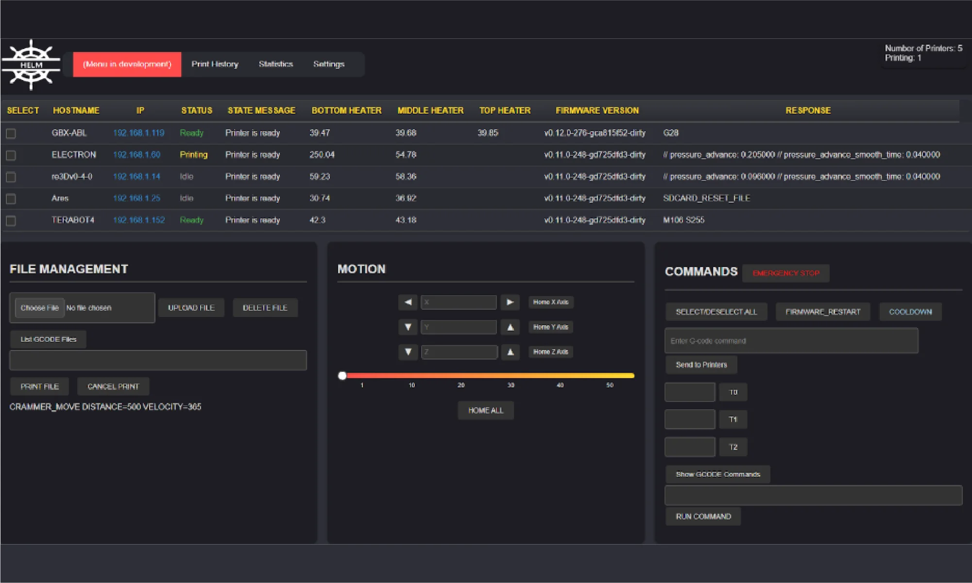
Figure 12: Helm dashboard.
Here are some of Helm’s key features:
- Server hosted on the local network for multiple clients
- Automatic network scanning to connect to printers
- Status monitoring
- Display of hostname, IP address, and firmware version
- Dynamic monitoring of status, state messages, temperatures, and command responses
- Multi-printer selection for command execution
- File upload/deletion
- Start/stop prints
- List G-code files on a particular machine
- List commands
- Send G-code commands
- Set temperatures
- Cooldown heaters
- Firmware restart
- Emergency stop
Helm is still a work in progress, but it’s an open-source project and open to contributions. You can try the application yourself, report problems, contribute, or follow progress here: Helm on GitHub. Helm is designed to simplify printer management and will continue to evolve with input from the community, ensuring it meets the needs of users managing multiple printers.
R&D Programs
re:3D is proud to have a robust R&D program, sponsored in part through industry and government awards and contracts. Each of these could consume its own blog post (and perhaps someday will, disclosure rules permitting). For now, here’s a brief summary of recent and ongoing programs re:3D is engaged with through the Department of Defense, NASA, the Department of Energy and the National Science Foundation.
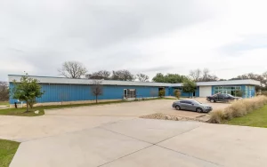
One of the visions of re:3D’s founders was to provide a means of production to people in need, who could fabricate parts from local and salvaged materials. The Gigalab is a huge step towards fulfilling that vision. Within a modified 20-ft shipping container, the Gigalab Mobile Recycling Facility can contain all of the equipment required to break down waste plastics to use as feedstock for printing functional items with a GigabotX printer. Multiple variants of Gigalabs have now been fielded at four locations: the Engine-4 coworking lab in Bayamón, Puerto Rico; an Army Corp of Engineers facility at Fort Leonard Wood, Missouri; Cannon Air Force Base in New Mexico; the Austin Habitat for Humanity ReStore location in Austin, Texas (Figure 13).
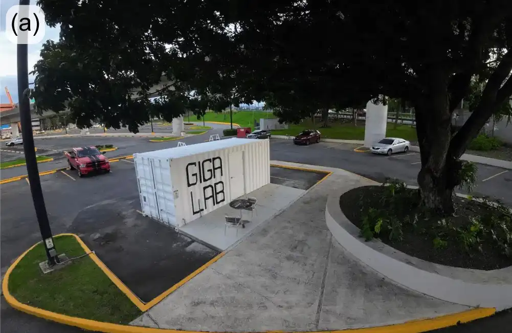
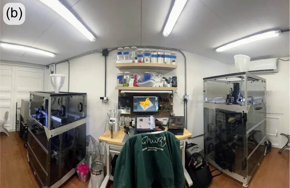
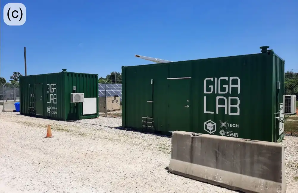
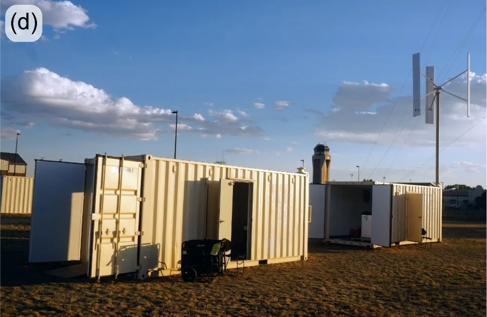
Figure 13: Gigalab at Engine-4 in Bayamón, PR (a-b); Fort Leonard Wood Gigalabs (c); Gigalabs with wind turbine power at Cannon Air Force Base (d).
You can learn more about re:3D’s Gigalab at Engine-4 in Puerto Rico in an earlier re:3D blog post here: October 2023. Last year’s highlights from the US Army and US Air Force Gigalab projects included logistics challenges, travel to Los Angeles to install a custom energy-management system and fabricating (and flying) small drones printed from recycled drones (Figure 14).
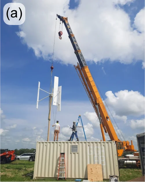
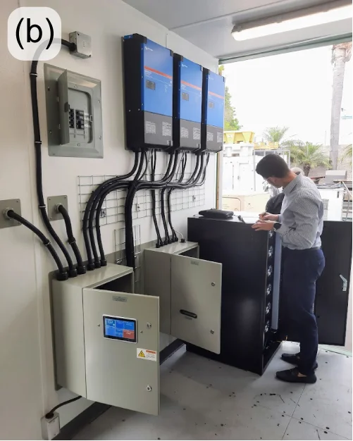
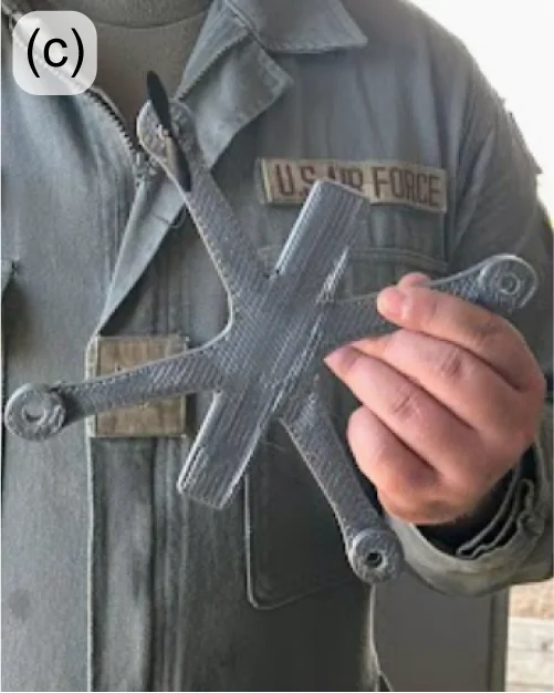
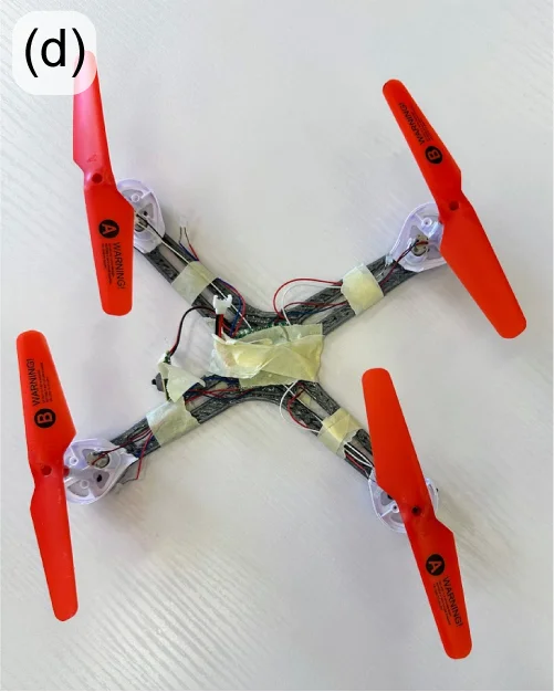
Figure 14: Installation of a wind turbine on a USAF Gigalab at re:3D’s Carmine, Texas interim test site (a); installation of a custom energy management system for the US Army Gigalabs at Wenzlau Engineering in California (b); iterations of printed “drones from drones” at Cannon Air Force Base in New Mexico (c-d).
ReCreateIt (NSF)
ReCreateIt is a multinational collaboration led by re:3D to transform waste plastic into valuable products with 3D printing and community-led design. The Gigalab located at the Austin Habitat for Humanity ReStore is a part of this program, which is funded through the National Science Foundation’s Convergence Accelerator. In order to maximize the value of “trash-to-treasure” in converting waste thermoplastics collected at the ReStore into printed goods of value, re:3D now employs a polymer scientist dedicated to this project who will investigate and optimize the processing and printing parameters to best recycle plastics via material extrusion additive manufacturing (3D printing).
Recent success in 3D printing with recycled polypropylene (PP) is evidence of the benefit of having a polymer scientist on staff. PP is the second most widely produced plastic in the world, and is commonly used for consumer items, including storage bins, which are available in large numbers for recycling at the ReStore (Figure 15(left)). However, PP is commercially recycled at a rate of less than 5% – partly due to industrial processing and economic challenges. Additionally, as with all members of the polyolefin family of polymers, it is notoriously difficult to use as a feedstock in 3D printing, even in a neat or virgin state, let alone as recycled granulate. But the perseverance and dedication of the ReCreateIt team is paying off as evidenced by the printed vase in Figure 15(right), along with many other great successes.
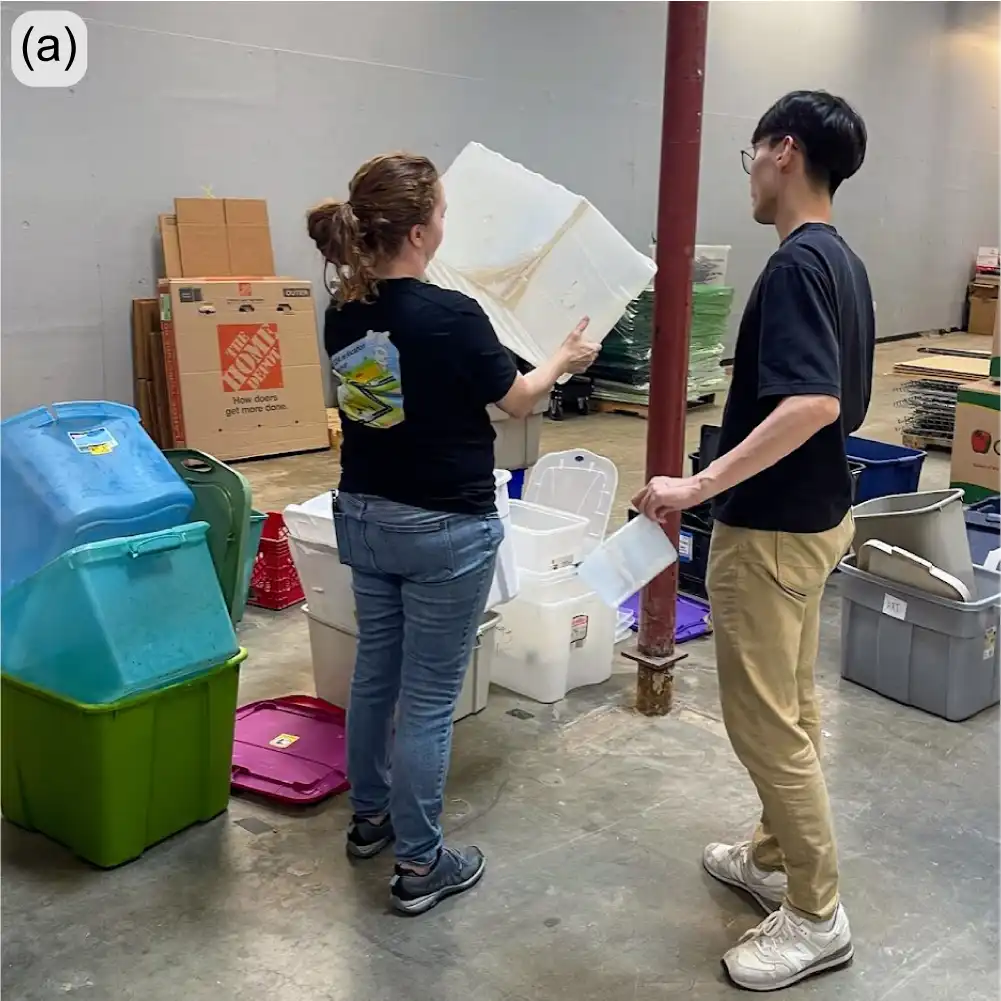
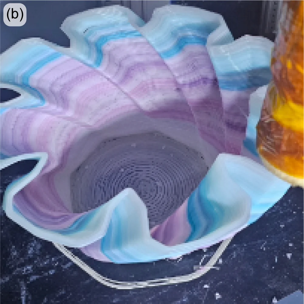
Figure 15: Members of re:3D’s ReCreateIt team sorting plastics at the Austin Habitat for Humanity ReStore (a); decorative vase printed from polypropylene laundry baskets and storage totes (b).
Low-SWaP Waste-to-Print System (NASA)
Remember the Gigalab – a converted 20-ft shipping container with the equipment to granulate plastics and print objects of use? Now imagine a similar system the size of a dorm refrigerator that uses half the power of a common space heater and is designed to work in space. This is the objective of a research contract re:3D was awarded through NASA for the Artemis Gateway program. The GigabotX has been repackaged into a low size, weight, and power (SWaP) version and integrated with a custom granulator (Figure 16(left). The system is intended to recycle packing foams which are necessary to protect payloads during liftoff, but are largely unnecessary once in space – or on the lunar or Martian surface. These foams can then be recycled for repair parts, construction materials or other items which would otherwise need to be delivered separately (at significant cost). The system isn’t ready for flight testing yet, but interim hardware demonstrations have already been performed for NASA on-site at Kennedy Space Center in Florida.
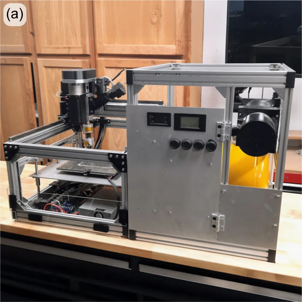
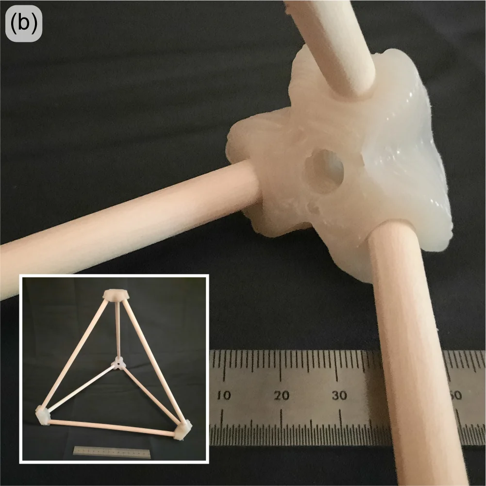
Figure 16: Low-SWaP printer and granulator system (a); tetrahedral dowel connectors printed from shipping foam (b).
“Bigger, Better, Faster” FGF (US Army)
Building on the success of one of re:3D’s R&D contract with the US Army to demonstrate printing from waste in a Gigalab, sequential funding was secured to print bigger, better and faster – using a wider range of recycled materials as feedstock. This will still be a cartesian FGF printer built on an extrusion frame, but larger in footprint than re:3D’s TerabotX (Figure 17). The extrusions are larger and stiffer, and the design is more easily scalable in the length axis to accommodate future development goals. The bed will be stationary with better access from the front and back to aid print monitoring and removal. For motion control, stepper motors are being replaced with servo motors for improved speed and torque performance, and linear screws are replacing belt drives for translation. The standard ArchiMajor control board will still be used, but a custom breakout board has been designed in-house to provide servo motor control, and the Klipper GUI interface is getting an upgrade to better reflect the operation of an FGF printer.
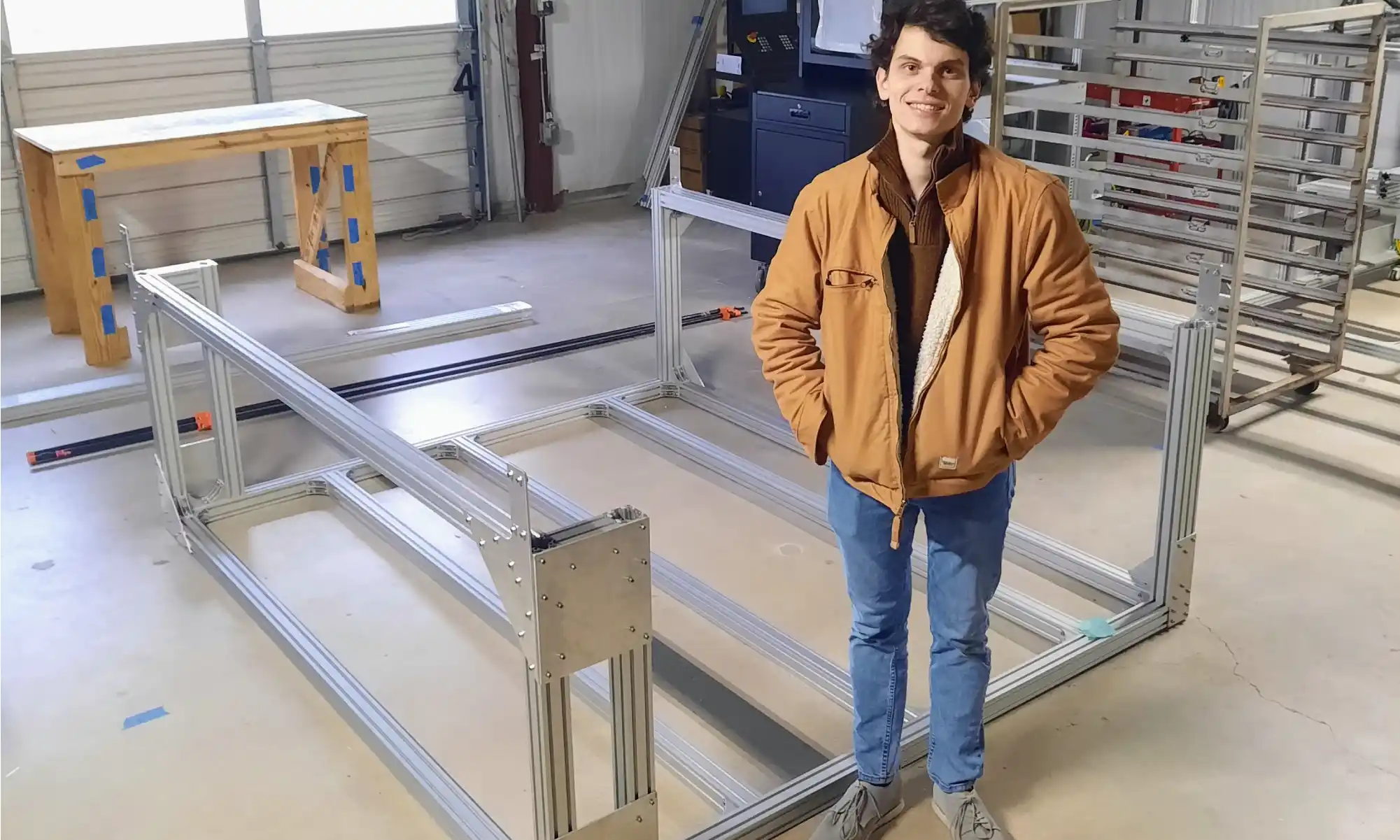
Figure 17: FGF R&D printer lower frame for the US Army. Hardware Engineer for scale.
re:3D is very pleased to collaborate with Dr. David Kazmer and his team at the University of Massachusetts Lowell to design, fabricate and optimize a new extruder with a novel screw for this project. The extruder length won’t change much from the existing GBX design, but the screw’s diameter will double and provide a very significant increase in throughput. Additional support is coming from the University of Maine’s Advanced Structures and Composites Center (ASCC). They will be leading the effort to develop recycled biocompounds – that is, feedstock materials produced from recycled polymers and wood or paper waste. This is an exciting R&D project with many possibilities for cross-development into re:3D’s portfolio of standard printers and other collaborative opportunities.
Additively Manufactured Thermal Protection Systems (NASA)
When a spacecraft enters a planet’s atmosphere, friction generates extreme heat which can damage the craft and payload (human crew or otherwise). Thermal Protection Systems (TPS) are materials designed to insulate and dissipate that heat energy – often through charring and re-radiation. Under an R&D contract with NASA / Johnson Space Center, re:3D is developing a pilot manufacturing system to print TPS materials directly onto spacecraft heatshields and other structures. Dr. Brett Compton and Dr. Damiano Bacerella (University of Tennessee – Knoxville) are developing and testing a phenolic-based foam, which when cured at elevated temperatures forms a ceramic-like TPS structure (Figure 18(a)). re:3D, in turn, is designing and building a printer to deposit the foam onto a large, non-planar aluminum dish. This requires a 5-axis printer with advanced controls (Figure 18(b-c)). re:3D is collaborating with Siemens/CATCH on the industrial motion control system, and with Addiguru for deposition monitoring.
Besides the unique opportunity to work on #supercoolNASAstuff, this project is giving re:3D additional experience with new industrial control systems, 5-axis tool-path planning and printing thermoset materials. Thermosets differ from thermoplastics in that they start out in some fluid form and require heat to harden (rather than just melting and recooling, as do thermoplastics). This gained experience with thermosets will allow re:3D to provide new opportunities to work with customers on a wider range of material extrusion projects. The deposition monitoring system being spearheaded by Addiguru may also be modified for future inclusion in re:3D’s commercial products. Finally, this provided the R&D team a reason to purchase a large truck oven (Figure 18(d)) for curing the TPS foam after it is deposited onto the aluminum dish. It might also be for a dual-use on Pizza Fridays.
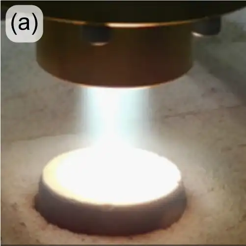
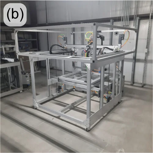
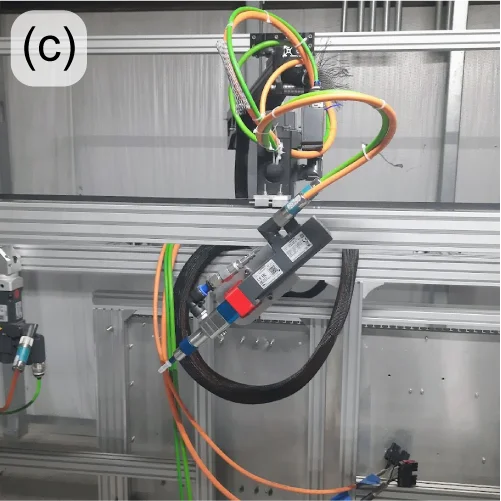
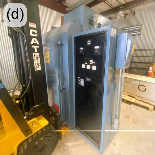
Figure 18: High-energy testing of TPS foam (a); AMTPS printer frame (b); ViscoTec deposition head on multi-axis mount (c); Blue-M truck oven (d).
Water Bottle Granulation (DOE)
Through a Cooperative Research and Development Agreement (CRADA) with Oak Ridge National Laboratory in Tennessee, re:3D is partnering with Oak Ridge’s Manufacturing Demonstration Facility (MDF) to develop a low-cost and accessible granulator that can break down water bottles into appropriate flake (Figure 19(left)), even if they are still full of water. Collaborators at ORNL/MDF are also investigating the best ways to separate the different polymer components of the granulated water bottles (Figure 19(center, right)) so they don’t have to be pre-processed to remove the lids, safety rings and labels – often done manually in small-scale operations. Phase II of the project was approved in 2024.
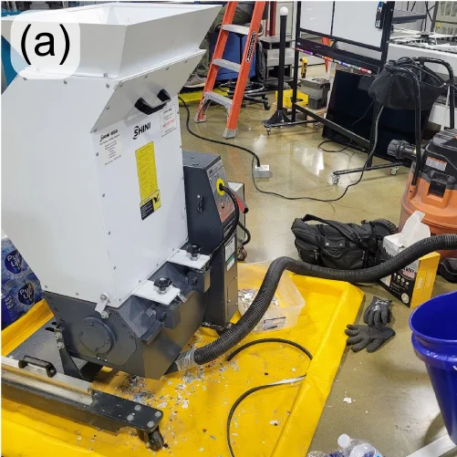
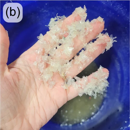
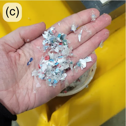
Figure 19: Plastics granulator with modified controls to safely process wet water bottles (a); separated water bottle flake: PET bottle portion (b) and PP/PE lid and label portion (c).
This was a long post. But there was a lot to cover from last year, and it’s been awhile since an engineering update was posted to the blog. Thanks for sticking with it, and stay tuned for more (frequent) updates.
As always… Happy Printing!
References
[1] 3DBenchy.com
[2] Al Nabhani, D.; Kassab, A.; Habbal, O.; Mohanty, P.; Ayoub, G.; Pannier, C. Benchmarking the Tensile Properties of Polylactic Acid (PLA) Recycled Through Fused Granule Fabrication Additive Manufacturing. In Proceedings of the Solid Freeform Fabrication Symposium, Austin, TX, USA, 14–16 August 2023. https://doi.org/10.26153/tsw/50919
Patrick Ferrell
Senior Engineer