Getting a grip on your 3D printer filament Part 2 by Chief Hacker, re:3D
One of the leading causes of print failure is the filament feeding mechanism. By surveying the literature and leveraging our current experience in hardware development we have identified a gap in the knowledgebase for understanding the mechanics and operations surrounding the extruder drive gear commonly used on FFF type 3D printers. The goal of this work is to characterize the amount of force that can be generated by a custom machined extruder drive bolt, affectionately named “Jaws”. Details of the engineering development of Jaws is outlined in part 1 of this series. The testing outlined below was performed with a Greg’s Wade’s type extruder for 3mm PLA filament. See Figure 1 below.
Figure 1. Greg’s Wade type extruder
The first objective of the multipart study is to determine the optimal tension setting for the Greg’s Wade extruder. Tension is adjusted by rotating a pair of screws that compresses a pair of springs that in turn presses the extruder’s idler bearing against the filament. See figure 2A below. This presses the filament into the teeth of the filament drive bolt seen in Figure 2B below.
Figure 2A Tensioning system and force arrow
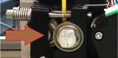
Figure 2B “Jaws” Filament Drive Bolt
If the tensioner is adjusted too loosely the filament will not fully engage against the teeth of the drive bolt. If the tensioner is adjusted too tightly there may be excessive friction and wear in the extruder. To accurately measure the force imparted to the filament by the extruder we felt it was important to measure the ability of the extruder to push the filament down into the hot-end. Previously, force measurements commonly seen in the literature measure the amount of pull the extruder imparts in the filament coming into the extruder. We felt that by measuring the amount of push we would obtain better real world operating conditions.
The downward force measurement was accomplished by a custom machined fixture that housed a small metal ring outfitted with a threaded tensioning system. The tensioning system is used to slowly grip the filament by turning a screw. As the ring increases its grip on the filament the force is transferred from the filament and onto a compression load cell (THA-100-Q from Transducer Techniques). The load cell was connected to a load cell amplifier (TMO-1 Transducer Techniques) and the analog output from the amplifier was measured by a 12bit A to D daq (USB-1208LS from Measurement Computing). Data was collected at 100 Hz and saved to csv file format. The daq was calibrated using a mass of solid brass and aluminum of known volume. Collected data was processed and graphed using custom Matlab code. The extruder is driven with a 1.68 A 72 oz-in NEMA 17 stepper motor powered at 24 volts. Test setup seen in Figure 3 below.
Figure 3. Test setup with force measurement
Three trials were performed at four different levels of tensioner adjustments. Tensioner adjustment levels were determined as 2, 4, 8 and 12 revolutions (1 revolution = 360 degrees of rotation) of the tensioner adjustment screw beyond full engagement into its corresponding nut. Example trials are shown in below. Notice in the data graph the period of zero force at the beginning of the trial followed by a gradual increase of force. The force curve shows the peak force imparted into the filament followed by a sharp drop in force where the filament drive gear stripped the filament and filament drive bolt was no longer able to impart a force into the filament. The graphs seen in Figures 4-7 below shows the ability of the filament drive bolt to drive the filament at increasingly greater forces with an increase of tension in the extruder tensioner system.
Figure 4. Tensioner tightened 2 revolutions
Figure 5. Tensioner tightened 4 revolutions
Figure 6. Tensioner tightened 8 revolutions
Figure 7. Tensioner tightened 12 revolutions
What does this mean for you? With the Greg’s Wade type extruder and the Jaws filament drive bolt we were able to push the PLA filament with over 50lbs of force when the extruder tensioner was advanced 12 revolutions. This researched establishes a baseline measurement for re:3D’s custom extruder bolt which was designed to maximize the grip on PLA filament and help ensure an error free printing experience. This research was conducted at the office of re:3D in Houston Texas.