Due to a busy Q2, we never got around to posting our Q1 2026 engineering update. Some of the content is a little dated by now, but we still wanted to share the good work going on in Product Development and R&D. We'll have another (more timely) update posted soon.
Product Development
Insights & Update from Domenic Cordova
High Flow Hotends
Recently we have been looking at different hotend solutions that allow for higher volumetric flow rates. The two hotends that we have been testing are from Slice Engineering and Microswiss, both with 100W heaters as opposed to our standard 65W. From Slice Engineering we have specifically been testing the Mosquito Magnum+. This hotend can reach volumetric flow rates up to 90mm3/s as an absolute maximum, but around 60mm3/s in real world scenarios, as opposed to the 12-15mm3/s that the current hotends are able to achieve. This increase in flow rate allows increased print speeds, reducing print time by up to 77%. We have developed a conversion kit for the Gigabot that allows for easy implementation of the hotend into any GB4 or TB. This kit is currently in Beta Testing, and we are actively recruiting for beta testers with hopes to release it to the general public soon (Check out our Beta Testing page to apply).

From Microswiss we have been specifically testing their FlowTech style hotends. This hotend can reach volumetric flow rates up to 36mm3/s as an absolute maximum, and 30mm3/s in real world scenarios, again a significant improvement from our current offering. This hotend also has a unique heater construction using an integrated ceramic heater as opposed to a barrel heater, allowing for faster and more responsive heating.

This hotend also has a unique nozzle construction that integrates the thermal tube and the nozzle, virtually eliminating the chance of leaking. This unique nozzle construction also allows the ability of changing the nozzle while the hotend is cold, making nozzle changing incredibly simple.The testing and development of this kit is still early on, but we will be looking for beta testers soon!

Both of these kits will include the implementation of improved part cooling with the use of a 5015 radial fan that reaches speeds up to 8500rpm. The improved part cooling allows for maintaining the same quality expected from Gigabot at higher speeds.

Research & Development
Insights & Updates from Patrick Ferrell
GigabotXS: Low-SWaP Waste-to-Print System (NASA)
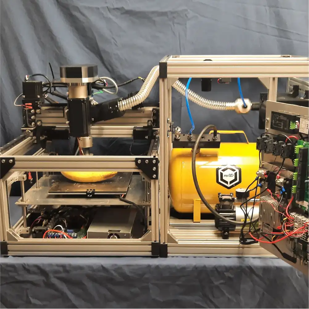
re:3D successfully submitted the final deliverables to conclude our NASA SBIR Ignite Phase II effort last Fall. This work, supported by the Deep Space Logistics team at NASA / Kennedy Space Center, developed an integrated waste-to-print system to convert logistics and packaging foam into useful objects via 3D printing – without requiring gravity! The next step is to test the system under reduced gravity to evaluate its performance in microgravity (zero-g) and lunar gravity (⅙-g) conditions. This will be accomplished through a parabolic flight campaign supported by NASA in the coming year – now that the SBIR/STTR program has been fully reauthorized by the government and contracting can resume. This will be an exciting experience for the re:3D team, so watch for more updates on this project soon.
5-Axis Direct Ink Write (DIW) AMTPS Printer (NASA)
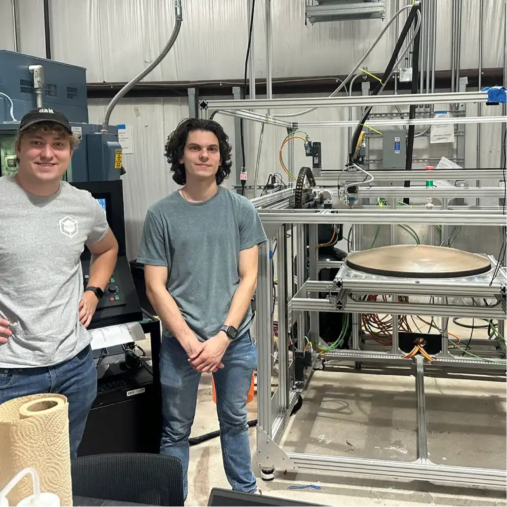
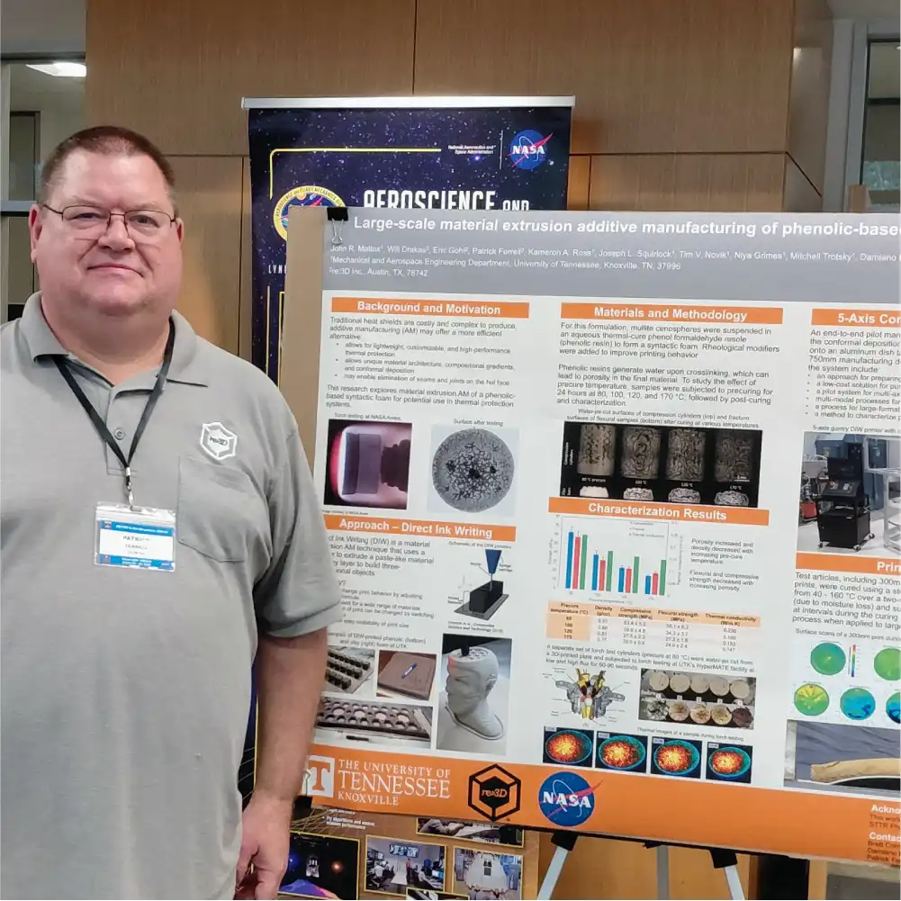
Also last Fall, re:3D closed out our NASA STTR Phase II work in collaboration with Dr. Brett Compton at the University of Tennessee – Knoxville. This effort was re:3D’s first serious investigation into printing with thermosets, and the opportunity to apply this technique to protecting spacecraft during atmospheric entry for NASA was fantastic. While the system still has some technical bugs, the team received high compliments from our NASA customer for the development of the printer and the delivery of a large-scale (750-mm diameter) manufacturing demonstration article from our pilot system. Patrick Ferrell had the honor of presenting this work on behalf of the team during a recent NASA AM-TPS TIM held at Texas A&M and will also be presenting an overview of the project success at ICAM 2026, to be held in Orlando, Florida, this coming September.
Bigger, Better, Faster FGF Printer (US Army)
A LOT of progress has been made on the Army xTech SBIR Phase II-Sequential project since the last blog update. Our collaborators at the University of Massachusetts Lowell (UML) made improvements to the extruder screw design to improve consistency and increase throughput, and this new version was installed last summer. The UML team has instrumented their extruder with an intrusive melt thermocouple and pressure transducer which is allowing them to validate their numerical modeling and begin to develop a method for modifying extrusion parameters such as screw speed and barrel temperatures based on ‘look-aheads’ in the toolpathing G-code. This will be a huge advancement for FGF printing systems.
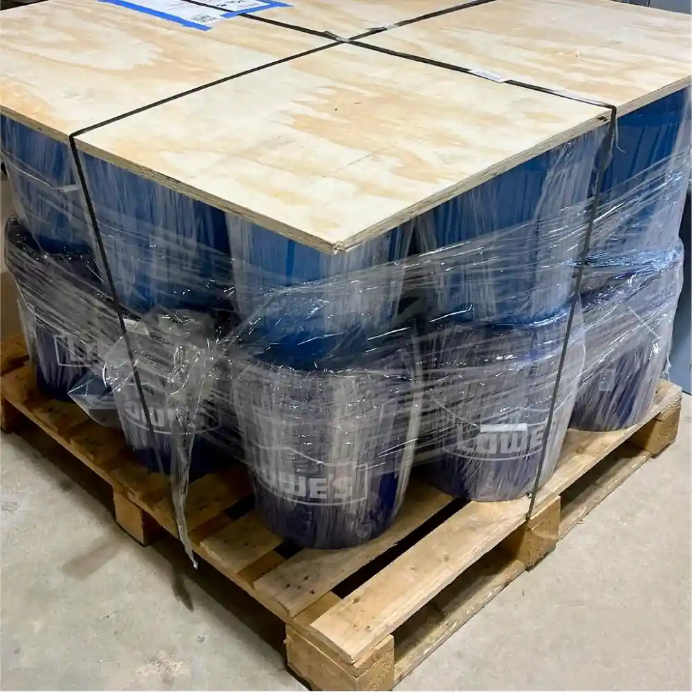
Our collaborators at the University of Maine’s Advanced Structures and Composites Center (ASCC) have been testing more than a dozen different polypropylene, polyethylene, woodflour and compatibilizer combinations to explore ways to recycle multiple polymers combined with organic waste. UMaine/ASCC has recently delivered over 200 kilograms of down-selected feedstock to re:3D for final demonstration test printing to take place over the next couple of months.
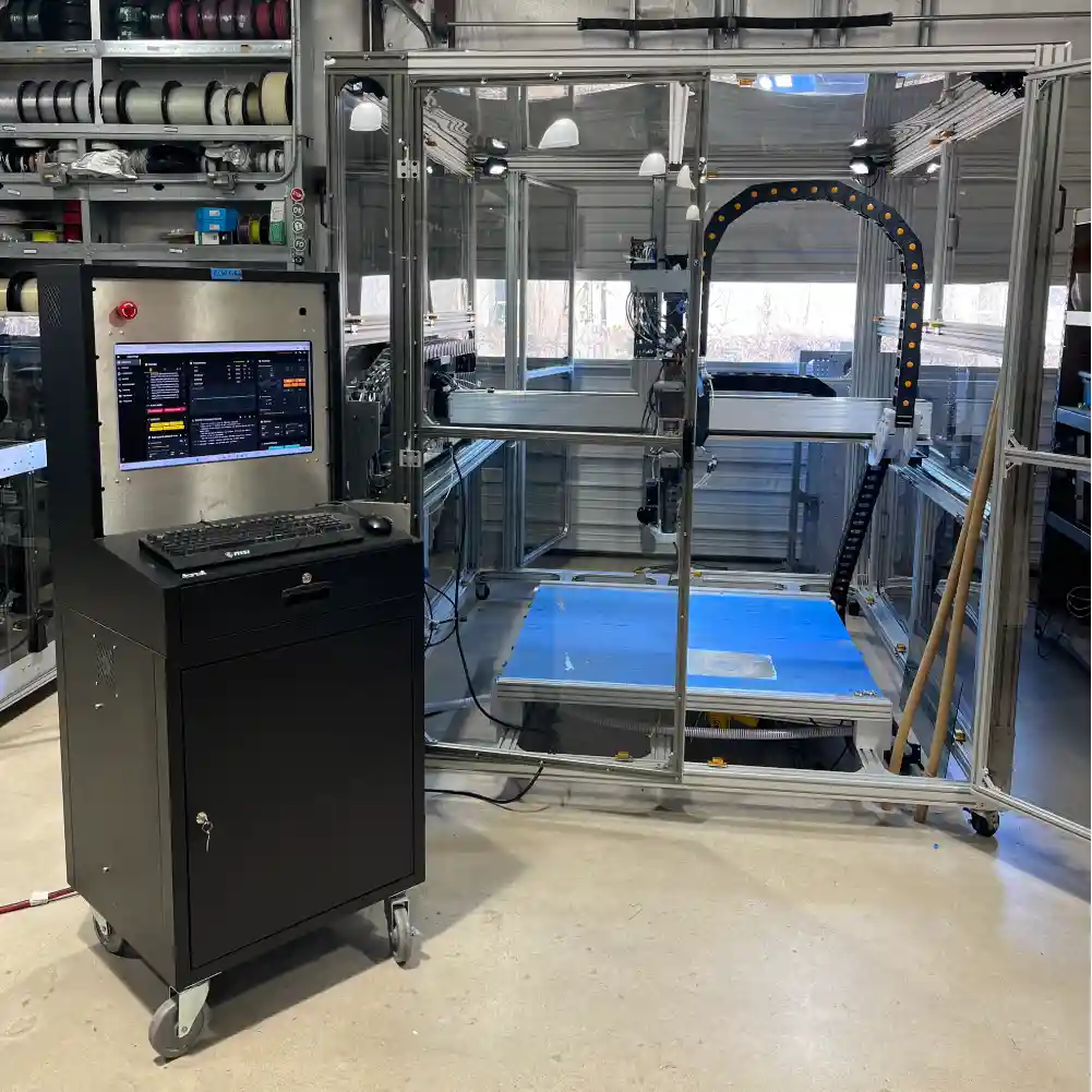
The printer itself has come a long way as well. Improved feedstock delivery, a superb part cooling system and lots of ‘quality of life’ enhancements have been implemented since last summer. The team has recently completed installation of the 3100 Watt heated bed and is beginning the final demonstration prints for our Army customers to conclude the project this summer.
LunaRecycle Centennial Challenge (NASA)
After sitting out Phase I, re:3D made a late decision to participate in Phase II of NASA’s LunaRecycle Centennial Challenge to build a prototype system to recycle a variety of materials anticipated to be discarded during future crewed lunar operations – things like aluminum struts, cotton clothing and plastic packaging materials. The team developed the “LunabotXS” recycling system, which pairs the company’s commercial GigabotX FGF printer with a unique ‘Feedstock Processing Unit” (FPU) which will convert plastic film waste into feedstock for the GigabotX to print items that the team believes have merit and usefulness for lunar applications. After a period of review, re:3D was selected as one of 16 Phase II Milestone winners and will advance to the final demonstration round to be held in Tuscaloosa, Alabama, this coming August.
The team is now busy building, testing and integrating the subassemblies on the FPU in preparation. But most importantly, the project now has a cool logo and even a ditty (or perhaps it’s a jingle – there’s some debate on that point). Full details, photos and videos of the design and operation of the LunabotXS will be shared once the competition concludes, so watch this space.

Insights & Updates from Eric Gohl
Since our last blog post I have spent most of my time working on the NASA IGNITE, Army Sequential, and LunaRecycle Challenge projects. During this time I have advanced our understanding of part cooling for large scale 3D printing, our understanding of the heat transfer dynamics of our printer enclosures, and helped our LunaRecycle team win $50,000 and advance to phase II of the challenge.
NASA IGNITE Ph II
Since our last update showing my work on developing a foam block magazine for the IGNITE system, I redesigned the granulator in order to shrink its size to allow for the installation of the new magazine. This did not take physical form, but was included with our report submission to NASA.

My granulator design uses a custom 3D printed gear to drive the cutting blades, while having the granulated foam pass through openings in the face of the custom gear. This allowed for the containment of the material, the avoidance of getting grinded foam into the drive mechanism, and a much smaller packaging.
Outputs of the System
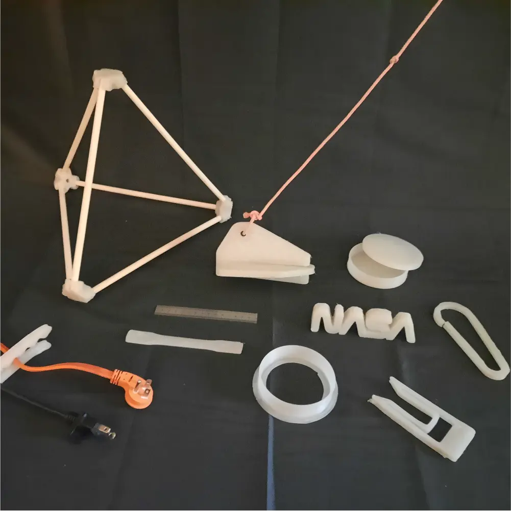
In order to demonstrate the value of having a printer like the IGNITE system in space, we printed demonstration articles to show the system’s capabilities. Since directly printing hook and loop tape is infeasible with our current design, we sought out to make a design that had similar functionality but was printable on our system. We needed a design that could interlock with itself under small force, and require a greater separation force than the application force. We also wanted the two surfaces to be able to be oriented in multiple directions, as opposed to just one. After over 100 design iterations and hours of testing, I was able to come up with the design that we have termed DINC’s, which stands for Discrete Interlocking Nodal Connectors.
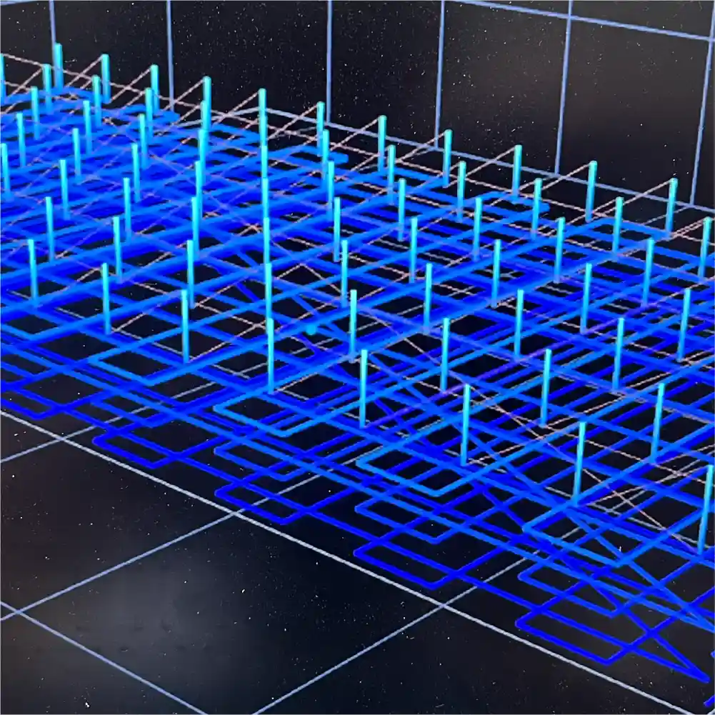
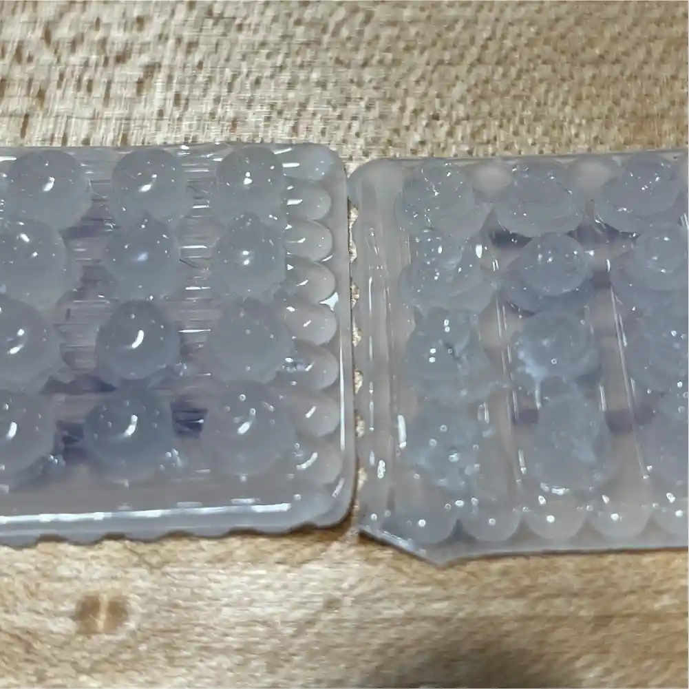
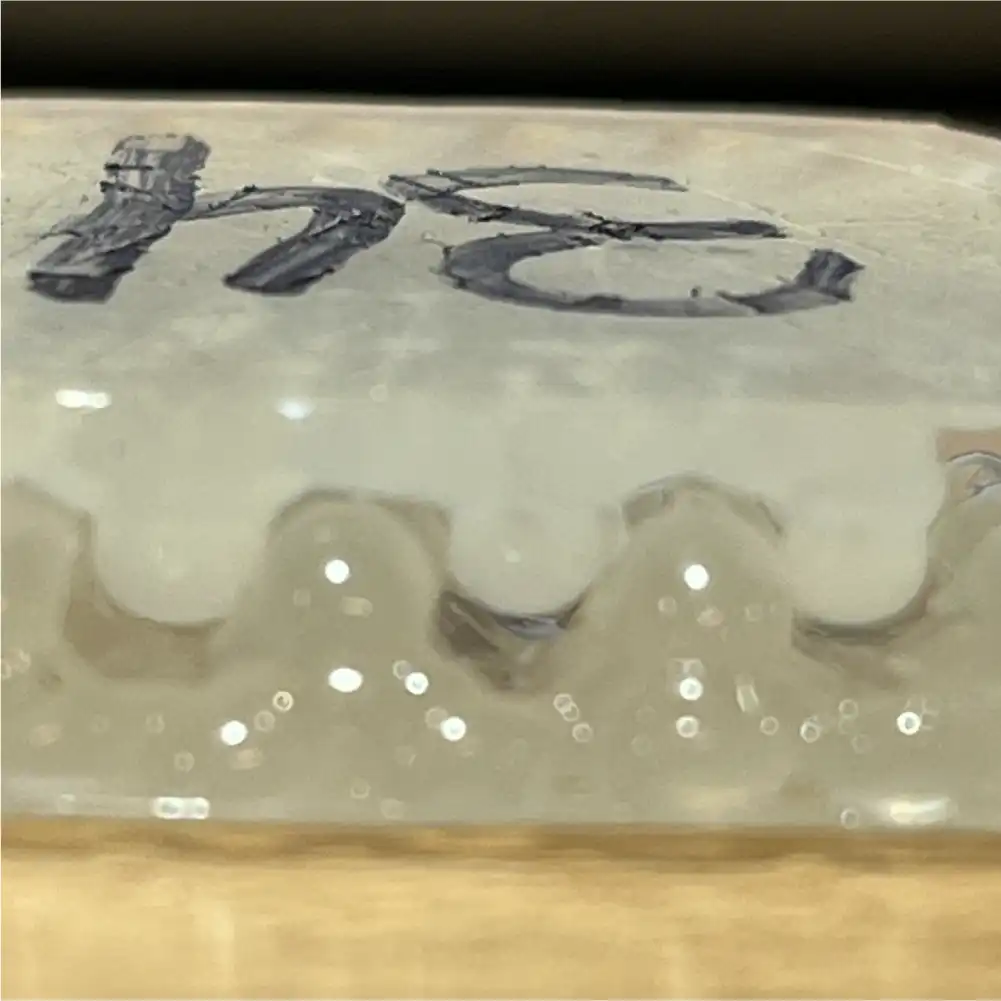
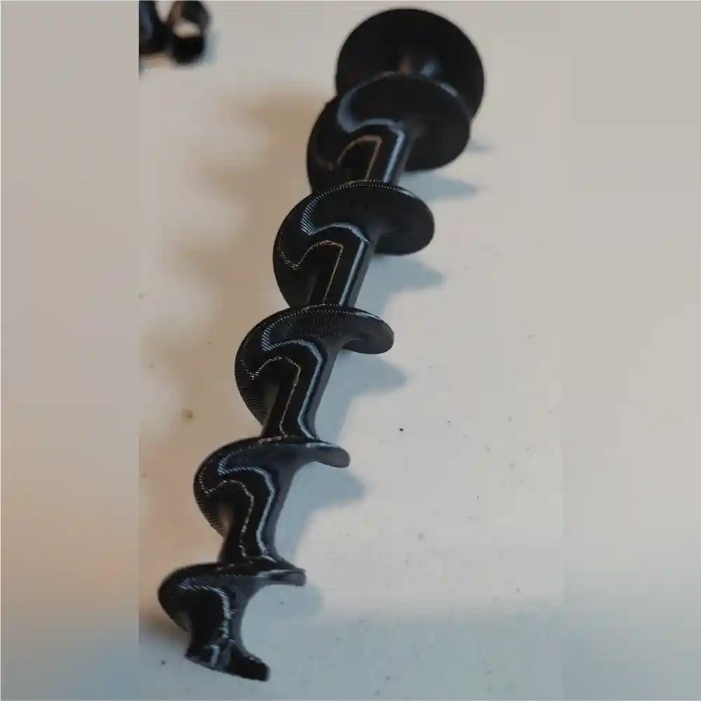
Discrete Interlocking Nodal Connectors (DINC)
These can be 3D printed on an FGF system, and were developed using the tool Full Control to generate the paths needed in order to produce the geometry seen above.
Army Sequential
After having the chance to test the first auto loader I was able to design a 2nd version that rearranged the orientation of the filter, adding a screwed-on cap, changed the way it interfaces with the feed tube (using a KF-25 vacuum fitting), and added a viewing window. I also designed a lower piece that the vibrational motor mounts to that has a spring-loaded chute to let material out, another window, and a smooth inner form to maximize material flow into the feed throat of the extruder assembly.

This design has greatly reduced any material starvation at the extruder output due to material bridging at the feedthroat.
After addressing those issues, I moved to working on part cooling. I started with trying to design a manifold that uses channel length to evenly distribute air flow to material at the tip of the nozzle. I also started with trying to use a large blower fan to provide air flow, and comparing that to using compressed air.
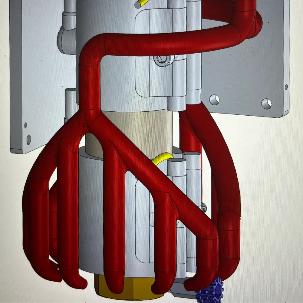
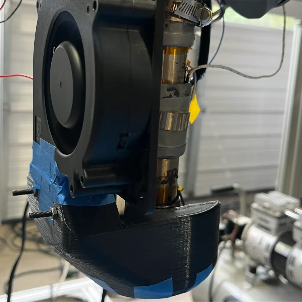
Both methods of air flow proved to be inadequate, as the compressor struggled to keep up with the high flow demands, and the blower fan was heavily throttled by the introduction of the manifold. I then did further research and found that some in the 3D printing community had turned to using a CPAP fan to provide high flow despite the introduction of a manifold to direct air. I also did further research on what the 3D printing community had learned in testing many different manifolds, as well as what the literature had to say. This is how I landed on my final design, which uses a CPAP fan mounted with its outlet as close as possible to the manifold exit, and a manifold that prioritizes smooth inner channels with slow transitions over a perfectly distributed flow, as can be seen below.
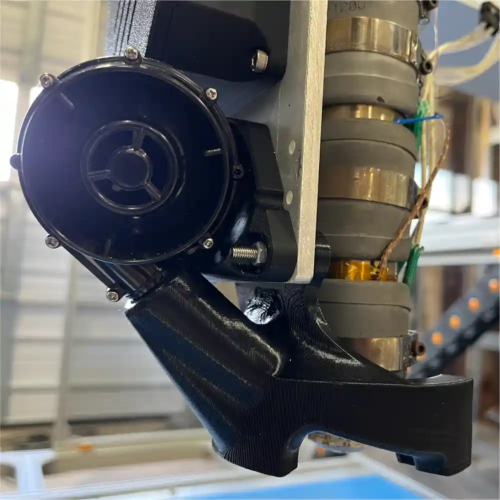
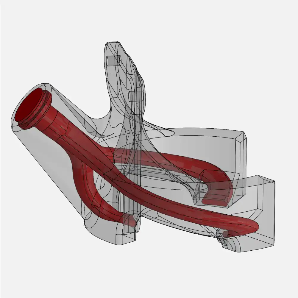
This design ended up being so powerful in terms of airflow, that actually we have to throttle it down to 25% at a maximum at our current print speed. In order to get the air speed properly calibrated to the layer time, I printed a steep cone and tuned the min and max values which are set based on layer times in OrcaSlicer.

The cone shown on the left had no part cooling for a control, the middle cone was too much cooling, and the rightmost cone, while still technically a failure near the top, was still considered a success for our purposes as it has a layer time shorter than what we would use in practical situations.

LunaRecycle Challenge
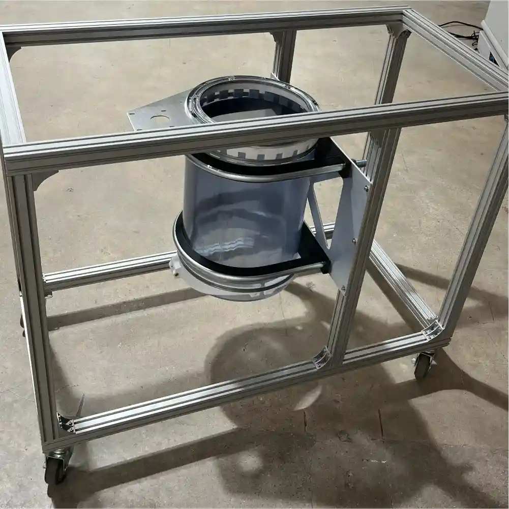
We submitted a conceptual CAD design for Phase I of the challenge, and we were fortunate to advance to Phase II with $50,000 to spend on creating a prototype. We are currently underway at building our design, and the work in progress can be seen below.
Insights & Updates from Chris Hong
ReCreateIt: NSF Convergence Accelerator Track I
The ReCreateIt project has been progressing very well, with Austin Habitat for Humanity ReStore’s Gigalab operations running smoothly. The interactive design tool developed by the Georgia Tech team is now fully operational at the ReStore. Many vases have been designed, printed in various colors, and sold through this design tool.
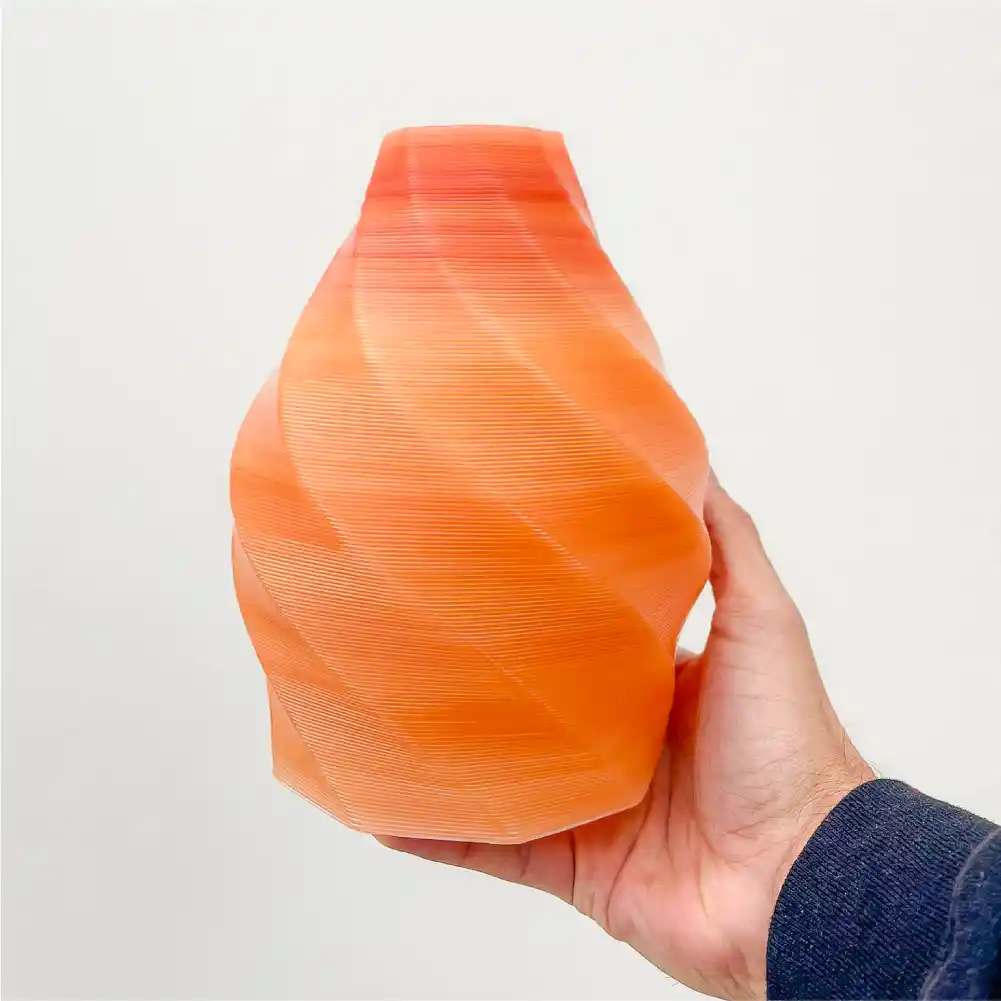
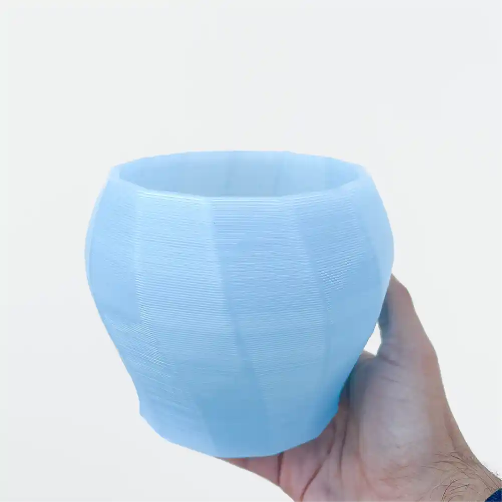
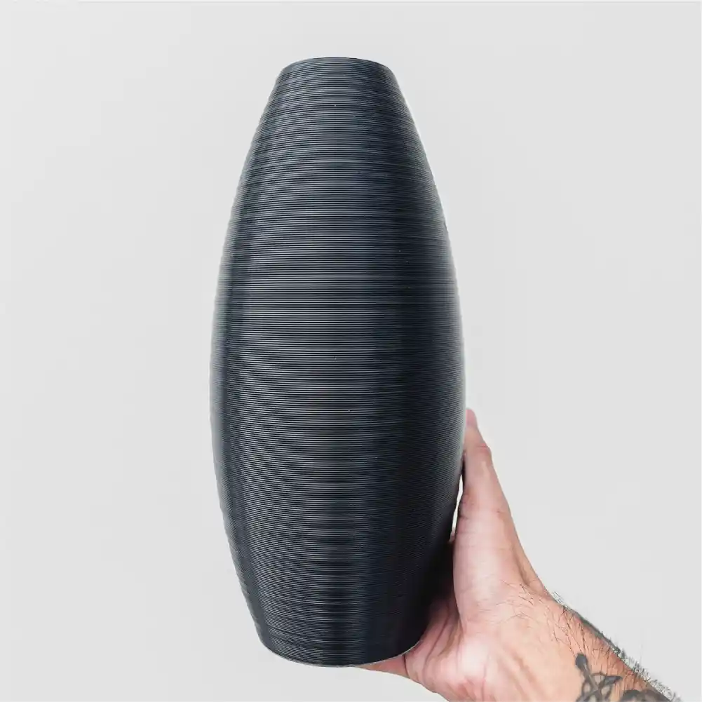
Figure. Vases designed by the ReStore team using the interactive tool
Thanks to the very creative minds on the team, a wide array of functional parts are being tested and sold as well. These include multi-color prints, mesh bags capable of holding over 20 lbs (!!!), tool holder bars with embedded magnets, cloth hangers, and more.
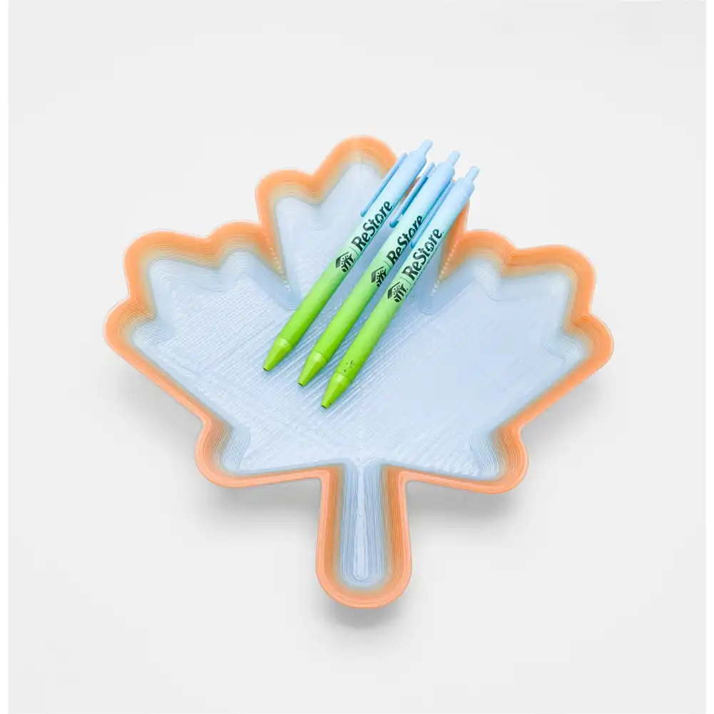



Figure. Other creative prints from the ReStore team
The polymer research efforts within the ReCreateIt project have also been progressing smoothly, and provided valuable insights over the past quarter. One of the primary concerns that ReStore customers raised during on-site interviews was about the strength of recycled plastics. It is no secret that the mechanical properties of polymers degrade over time (UV and environmental exposure) and thermal cycles (extruding, melting, etc). To address this concern, the ReCreateIt team conducted a handful of tests to determine whether such degradation poses a serious concern for our project, particularly for load-bearing applications.
The first test, conducted by Georgia Tech, compared the properties of the material before and after 10 extrusion (thermal) cycles using a GBX. As all before and after samples were injection molded, this test isolates the effects of the thermal history on the polymer itself, without being affected by the 3D printing process parameters and process-induced irregularities.
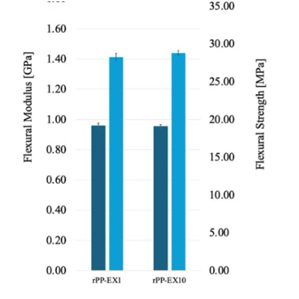
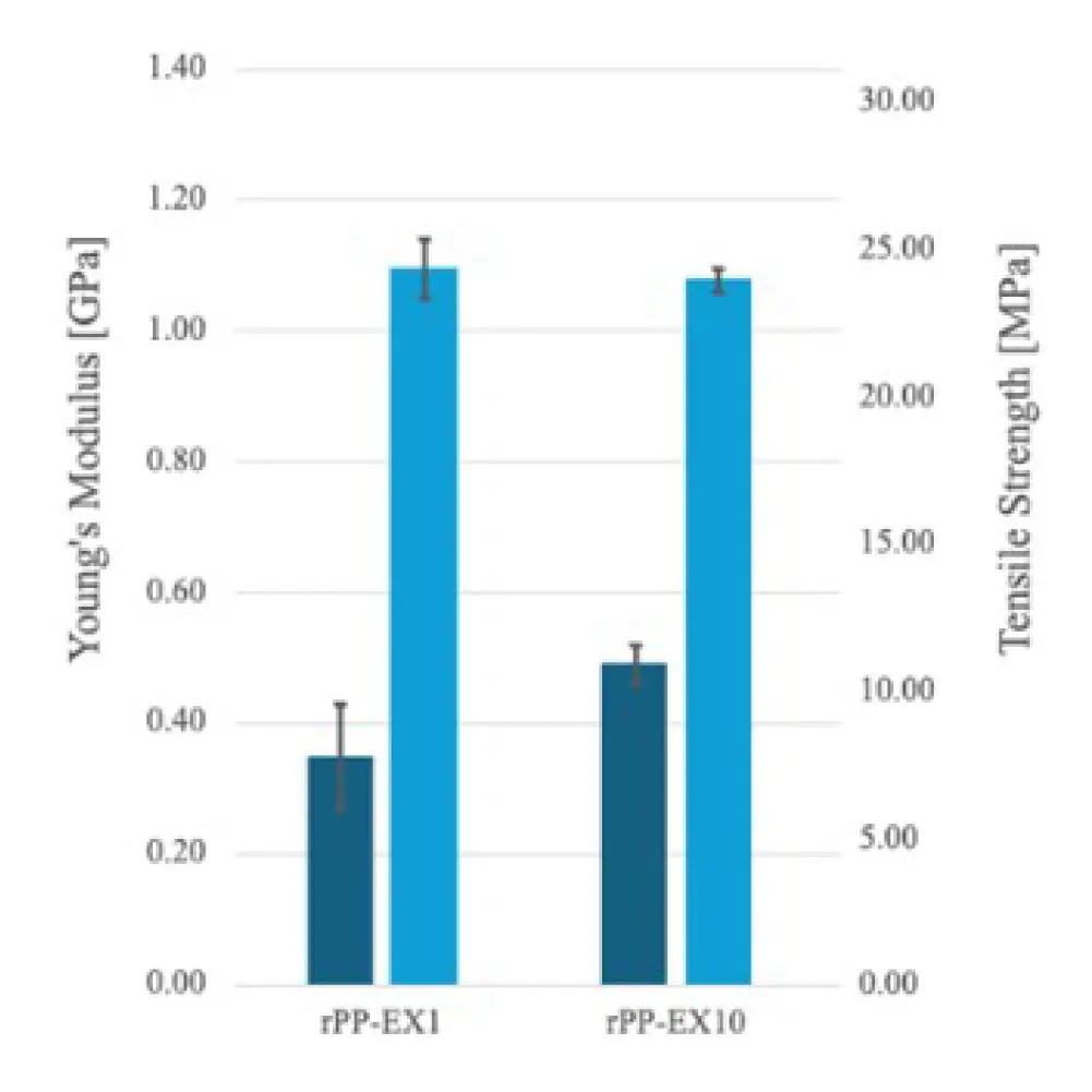
Fig. Degradation of tensile and flexural properties of injection molded samples after 10 extrusion cycles
The second test, conducted by Western Sydney University, also investigates the changes in mechanical properties over multiple extrusion cycles using a GBX. However, all test specimens are 3D printed, therefore reflecting the influences of processing parameters and process-induced defects.
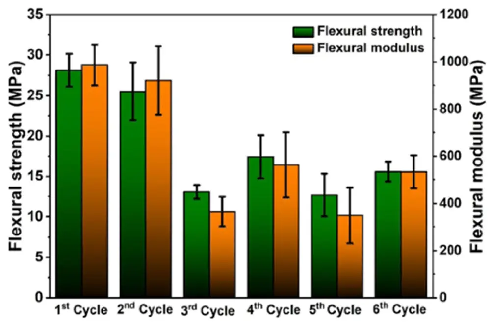
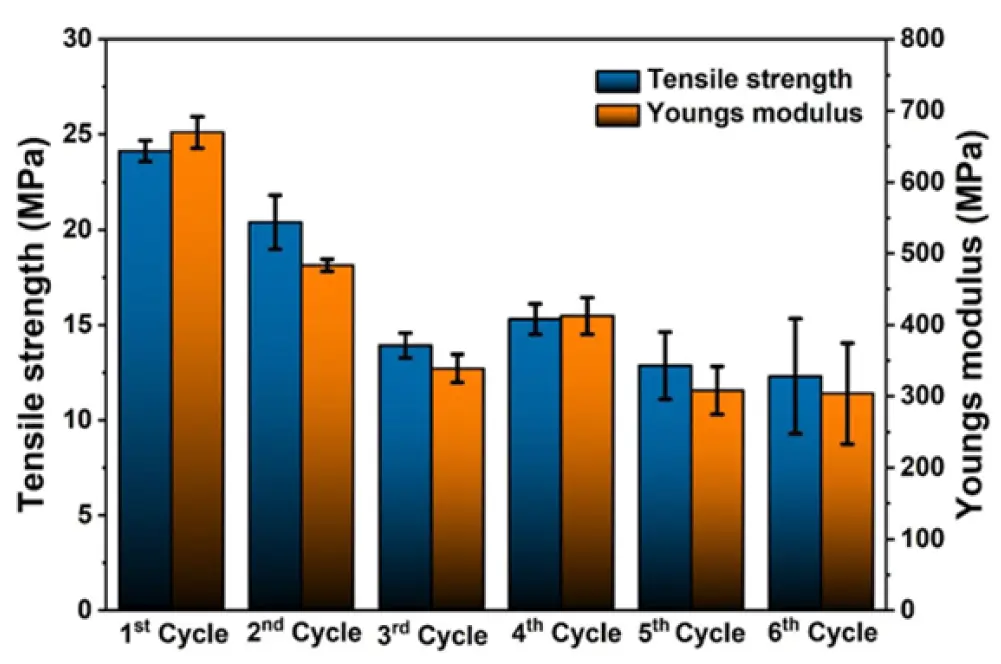
Figure. Degradation of tensile and flexural properties of 3D-printed samples over extrusion cycles
Lastly, the re:3D team worked with UT Austin’s CAMDI to conduct structural tests on full-scale 3D printed step stools designed by Mike. As a pilot study, only two full scale prints were tested under uniaxial compression on a MTS Criterion 45 test frame. To accommodate the size of the full-scale stools (318 x 318 x 244 mm), custom compression platens (approx. 11mm thick 6061 Al) were fabricated for the setup as shown below. Based on initial observations, future tests will double-up on bottom platens to prevent any curvature, which may introduce errors into the results.
The load-displacement curves for the two samples are shown below. The blue markers indicate local maxima, which are indicators of crack formation and propagation. Exceeding all expectations, both stools withstood well beyond 12,000 N (approx. 1,200 kgs / 2700 lbs) before initial crack formation.
Further testing on full-scale parts is currently paused, while the ReStore team is working with their legal team to identify potential legal concerns and liabilities associated with selling load-bearing items that users directly interface with. Depending on the outcome of this discussion, the extent of testing may increase significantly to include slip tests, tip tests, drop tests, fatigue tests and more, some of which are outside the UT CAMDI’s capabilities.


Software Engineering
Insights & Updates from Mitchell Mashburn
Firmware
Wrapping up from 2025, our firmware stack has had some major updates. It is now known as re:3D Klipper OS, a CustomPiOS built on top of FullPageOS (Debian Bookworm) which includes Klipper firmware and additional dependencies needed to operate the re:3D Gigabot printers. Using Github runners, every new commit creates a nightly image automatically with an in depth chroot script. This allows streamlined development and also makes community edits and customization accessible to anyone. All you need to do is fork the repository, commit changes, and an image will be created through Github actions. Along with system and backend improvements, a major feature that has been added is the configurator. Through the configurator you have the ability to select your printer type, set up networking, run automated tuning and calibrations, automatic log parsing troubleshooting, a dedicated updater, save and restore print history database and gcode files, and generate comprehensive calibration and print reports. At the time of writing, the latest version of re:3D Klipper OS is 1.3.0, with 1.3.1 releasing very soon.
Learn more and find the latest release here.
Helm
Helm has had a lot of development early in 2026. Full functionality has been implemented and deployed. Helm is now available as a precompiled executable for Windows, so that you don’t have to worry about the build chain and installing dependencies. Helm has had a lot of enhancements since the last update, including user management and admin control, sorting and layout options, networking configuration, fleet analytics, persistent task lists, accidental interruption prevention, and multi-lingual support (English, Spanish, French). We also have the honor of presenting Helm as a finalist for the 2026 TCT Software Award this April.
Learn more about Helm here.
Domenic Cordova
Patrick Ferrell
Eric Gohl
Chris Hong
Mitchell Mashburn
Blog Post Authors